SlideShare une entreprise Scribd logo
1  sur  16
Télécharger pour lire hors ligne
Paper No.
356
PREVENTION OF CREVICE CORROSION IN DUPLEX SS FLANGES USING CARBON
STEEL BOLTS WITH CATHODIC PROTECTION
W. H. Thomason
Conoco Inc
PO BOX1267
Ponca City, OK 74602
Randall G. Ivie
5051 N. Oak T& #4
Kansas City, MO
John A. Madow
John Madow Ltd
Sandhurst, Station Road, Barnby Dun
Doncaster DN3 lHQ, UNITED KINGDOM
ABSTIU4CT
Achieving reliable long-term performance of high strength bolts for flange connections in subsea service is a critical
issue for the offshore industry. Viable bolting materials with high strength that are not susceptible to embrittlement
or galvanic corrosion when the flanges are made of stainless steels are limited. A laboratory study was performed to
determine the viability of using B7 carbon steel stud bolts and316 stainless steel (SS) seal rings in a Duplex SS flange
for subsea service The laboratory test system used full size commercial flanges, bolts and seal rings to simulate
electrochemicalconditions that will occur in crevicesassociatedwith carbon steel bolts in a Duplex SS flange and with
the use of a 316 stainless steel seal ring in a Duplex SS flange. The flange systems were instrumented to enable
monitoring of current densities and potentials at precise locations within the crevices throughout the tests as test
parameters were changed. Test parameters includedcathodicprotection leve~temperature, and serdingthe outer flange
gap. Cathodic protection was provided by remote aluminumsacrificialanodesto achievepotentials typical for a subsea
manifold. Both electrochemicaldata and examination of the components at the end of the 164day exposure indicated
that stilcient cathodicprotection occurredin the crevicesto providelongterm corrosioncontrol to all of the components
involved. The capability to use B7 bolts rather than high alloy bolts enables a significant project savings.
INTRODUCIION
The Britatmia gaskondensate field is the largest remaining gas development in the U.K. sector of the North Sea. At
peak production it will supply approximately 10% of the U.K. gas requirements and has an expected field life of 30
years. The Britannia reservoir covers an area of approximately 40 x 10 kilometers and is located 210 kilometers
north east of Aberdeen in 140 metros of water. In order to maximize the gas extraction from the reservoir, two
production centers were used in the development. These area fixed platform and a subsea mdold 15 kilometers
Copyright
@999 by NACE International. Requests forpermiseion to publish this manuscript in any form, in parl or inwhole must be made in writing to NACE
International, Conferences DWision, P.O. Box 218340, Houston, Texas 77218-8340. The material presented and the views expressed in this
paper are solely those of the author(s) and are not necessarily endorsed by the Association. Printed in the U.S.A.
GabrielOnyeuka-InvoiceINV-980187-G4T2C3,downloadedon10/20/20155:17AM-Single-userlicenseonly,copying/networkingprohibited.
away tied back to the platform. The subsea manifold weighs approximately 500 tonnes and the pipework and
flanges are manufactured from 22% chromium duplex stainless steel. The subsea wellheads and flowlines to the
manifold are also mauufiwtured from duplex stainless steel. A schematic layout of the subsea system is shown in
Figure 1. All the pipework and equipment were deliberately electrically coupled to the CP system
At time when the subsca system was being design~ corrosion resistant alloy (CRA) materials were commonly used
for bolting in Duplex SS flanges. The Britannia Team handling materials selectionrecognizedthat significant savings
were available if standard, off-the-shelfB7 low-alloysteel bolts could be used on the subsea Duplex SS flanges instead
of the special order CRA Marinel bolts. Additional savings could also be realized if the 316 SS flange seal did not
require special corrosion protection (isolationo-rings and greasejacket). Although specifictest data werenot available,
results of previous cathodic protection studies’-5indicated that the normal cathodic protection system should provide
sutlicicnt corrosion protectionto a nonavered flangeto mitigateanyproblems due to the crevicesand galvaniccouples.
A laboratmy study was initiated to develop hard data, which would confii the viability of these approaches for the
subsea flange systems.
Considering the large number of flange bolts involvedand that the costs of Marinel bolts were 8.5 times the cost of B7
bolts, the potential savings were significant. In addition deleting o-ring seals and grooves on the flanges, deleting the
OD grease bands on the flanges, eliminatingthe need for spares, eliminatingthe costs of installing the grease bands on
site and subsea enable additional savings. Total potential savings appeared to be in excess of $500,000.
INDUSTRY EXPERIENCE WITH HIGH STRENGTH ALLOYS IN SUBSEA SERVICE
HAS NOT BEEN GOOD
Long term reliability of high strength metals under high stress in subsea service has been a problem in the subsea
industry for many years. This problem was exacerbated when the highly stressed materials were electrically coupled
to high alloy stainless steels and /or subject to cathodic protection. If the stressed materials were less noble than the
stainless steels they were subject to accelerated galvanic corrosion and crevice corrosion even when there was no
dissimilar couple. Cathodicprotection is used for most subsea systemsto protect the low alloycarbon steel components
such as well casings and pipelines. Many of the highly alloyed (CRA) materials under high stress are subject to
hydrogen embrittlement at potentials generated by the cathodic protection system and there are numerous reports of
failures. Replacement of these failed subsea components is almost always very costly.
LITERATURE REVIEW
A literature search was performed to identi~ experiences and data available regarding cathodic protection within
steellDuplexSSor316 SS/Duplex SS crevices. Severalstudies involving carbon steel crevice systemsl-3and stainless
steel crevices systems4have shown that CP is effectivein preventingcorrosion in crevices in seawater when the crevice
is under stagnant conditions. If there is activeseawaterflow into the crevice,CP is not effective. In general CP at levels
of-900 mV (Ag/AgCl) or mom negativewill nxiuceoxygenenteringthe crevicemore rapidly than the dissolved oxygen
diflhses into the crevice.
The literature search revealednumerous papers on creviceCorrosion’-gand the effect of CP14on crevicecorrosion. We
did not find a paper specifically addressing a crevicebetweencarbon steel and Duplex SS. A recent paper by MaurerG
cited an example of two stainless steels that uderwent crevicecorrosionwhen a crevicewas formedwith the two metals,
yet individually the metals were resistant to crevicecorrosion.
EXPERIMENTAL SYSTEM FOR DETERMINING IF CATHODIC PROTECTION WILL PREVENT
CORROSION OF CARBON STEEL BOLTS AND 316 SS SEAL RINGS IN A DUPLEX SS FLANGE IN
SUBMERGED SEAWATER SERVICE
The experimental system was designed to simulate actual subsea cmdition as near as possible. Actual Duplex SS
flanges, B7 bolts, and SS seals wereused. The experimentalconceptwas to measure the potential and current density
GabrielOnyeuka-InvoiceINV-980187-G4T2C3,downloadedon10/20/20155:17AM-Single-userlicenseonly,copying/networkingprohibited.
on the surfaces of the various components. These includedbolt and flange surfacesinside the boltholes and the crevices
created at the flange seal. The goal was to showthat anodiccmrent would not be generatedat any point on the B7 bolts
or SS seals. The generation of anodic current would indicate the occurrenceof galvanic or crevice wrrosion.
Two Duplex SS flange systems were instrumented for current density and potential measurements in crevices and
immersed in a test bath (1 x 0.5 x 0.3 m {depth})fdled with ASTM artiilcial seawater. The seawaterwas continuously
circulatedwith a pump, the temperaturewas initiallycontrolledat21° C, and the pH regulatedby twi= weeklychemical
additions. See Figure 2. A schematicdrawingof the instrumentedflangesused for this study is shown in Figure 3 with
the sensors on right used in the fmt flange and the sensors on the lefi used in the second flange. (A detail description
of the current and potential measurements will be presentedbelow.) The f~st flangecontained current sensors 1-7, and
the second flange contained one Duplex current sensor (8), the seal ring current sensor (9) and the referenceelectrodes
(El and E2). The B7 bolts in the fwst flange weretorqued (196 ft-lbs) to the maximum recommended stress (52,500
psi) per the API Spec. 6A. This maximum stress insured a minimum crevice opening between flange faces. For the
second flange, the seal ring was machined to reduce its thickness to permit electrical insulation of the seal ring while
achieving the minimum flange face separation with a smaller torque on the bolts.
Initiallyboth flanges werecatholically protected by two small aluminumsacrificialanodes placed as remote as possible
to the flanges and sized to achieve a nominal potential on the external surfaces of the flange of -950 mV (Ag/AgCl).
As cakareous deposits developedduring the exposure only one remote anode was required during the last-80 days to
maintain the desired potential (see Figure 2). By using the small aluminum anodes and controlling their submergence
depth (surface area), a potential and current density similar to that expected in subsea service was achieved. Most of
the CP circuit resistance occurred at the small anodewhichenabled achievinga uniform potential on the two flanges as
would be expected for subsea service from large anodes located remotely. Thus the CP current density available for
protecting inside the flange crevices closely approximate that in subsea service.
The pH was controlled to a target value of 8.2 by additions of concentratedNaOH twice a week. The pH of the bath
tended to decrease with time due to the loss of carbon dioxide to the air. HCI was used to lower the pH if the NaOH
addition caused an over correction. The common pH range was 8.5 to 7.5 with maximum excursions to 7.0 and 9.0.
Duc to the heat input tim the circulatingpump, we fd that we couldonly controlthe temperaturedown to 21°C with
our present test system. Since a complex test system would have to be assembled to maintain the planned temperature
of 8°C, and there was no reason to expect any different electrochemicalphenomena at the lower temperature, it was
decided to use the present system for the long term exposure and perform a one day exposure at -8°C. A low
temperature of 6°C was achieved for 24 hours by adding ice cubes made with fkozenseawater to the test bath.
Current Density Measurements -The rightside of the Figure 3 schematic illustrates the approach used for current
density measurement. The effectiveness of CP in the creviceswas determined using the zero resistance ammeter of a
PAR Model 173 Potentiostat to measure the current flow impinging on small plugs (approximately 10 mm2exposed
area) of material electrically insulated from their host component. Since the plugs could be located precisely in the
creviceareas of interest CP within the crevicescouldbe evaluated. Currentdensity is a direct measure of corrosion rate
if it is anodic and an indication of protection if the current is cathodic. The lead wires from all the current sensors were
shorted to the flange systcm except when current measurements were made with the zero resistance ammeter.
InFigure 3 plugs 1-4 were machined from a spare bolt with the external contour maintained. The bolt was drilled to
host the plugs and permit lead wires to exit the bolt. The plugs were securedwith an insulating epoxy and the bolt ID
filled with epoxy. Plugs 5-8 were made of Duplex SS cut tlom the flange and epoxicd in place as the steel plugs. The
plugs were slightly recessed to prevent their making electrical contact with the material on the opposite side of the
crevice. The 316 SS seal ring in the second flangewas used as current sensor number 9. The seal ring was coated and
wrappedwith electricaltape except for a 30 rmnzholidaylocatedjust opposite the flange’souter creviceto enable current
monitoring. (At the end of the test it was found that holiday area was greater than 30 mm2.) The seal ring had to be
electrically insulated from the flange faces in order to measure the current passing through the crevice and impinging
GabrielOnyeuka-InvoiceINV-980187-G4T2C3,downloadedon10/20/20155:17AM-Single-userlicenseonly,copying/networkingprohibited.
on the seal ring surface. The zero resistance ammeter enabled accurate measurement of very small galvanic currents
between the plugs and bulk flange material.
Multiple currentplugs wereused as insuranceagainstplugs becomingelectricallyshortedto the flange. Due to the small
size of the plugs, the small crevices, the torquing of the flange bolts, and the anticipated build-up of deposits, shorting
was a concern. Plugs 4, 5, and 7 experienced shorting during part or all of the exposure.
Differencesin current densities with and without CP would verifj if corrosionmitigation wereocmrring in the crevices.
The anodes/flange circuit was interrupted on three occasions to verify the CP effect. With no cathodic protection the
following was expected:
. The steel plugs (1-4) would be anodic to the Duplex SS with the resulting current flow being a direct measure
of corrosion rate.
. Current flow to plugs 5 and 7 would be a combination of cathodiccurrent pickup with the steel bolt serving as
the anode and an anodic current generated by the crevicemechanism.
. Current flow to Duplex SS plugs (6& 8) would be a combination of anodic current generated by the crevice
mechanism and galvanic current generated by the 316 SS ring and Duplex SS couple.
If cathodic protection is effsctive within the creviceexpectations are:
. All of the steel and Duplex SS plugs and the316 SS ring will indicate a cathodic current pickup. The greater
the current pickup the better the protection.
. Similar current densities for all current sensors will indicate no galvanic effkcts with CP.
. The presence of CalCarCOUS deposits on exposed metal surfaces at the completion of the exposure will indicate
that protective potentials were occurring on those surfaces.
Potential Measurements - The left side of the Figure 3 schematic illustrates the approach used for potential
measurements. Micro silver-silver chloride electrodes(3.0 mm diameter) weremounded in holes drilled in the Duplex
SS flange (see Figure 4) to enable potential measurementswithinthe flange-boltcreviceand the flange-sealring crevice.
The potential data will indicate anodicor cathodicconditions and complementthe current densily data. The two silver-
silver chloride electrodes were calibrated against the calomel electrode used to measure the potential on the external
surfaces of the flange. The E2 electrodefailed betweendays 80 and 94. It was remov~ the AgCl surface regenerat~
recalibrated, and reinserted in the flange before day 115.
RESULTS OF 164 DAYS SEAWATER EXPOSURE
Electrochemical measurements were daily made throughout the exposure. Several perturbations were imposed on the
systems throughout the exposure to observe the response of the CP system. The responses observed all indicate quality
CP within the crevices. At the end of the exposure the two flange systems were dismantled and the components
examined to determine if any corrosion had occurred and to determine the quality/extent of the CP by the calcareous
deposits.
Electrochemical Data - Theelectrochemicaldata are presented in Figures 5-7. System responses to the perturbations
are summarized in Table 1. Figure 5 presents the potential of the external surfaces of the flange and the increase in
potential observed inside the bolt hole creviceand the flange seal crevicerelative to the external potential. The current
densitydata shown is presentedin Figures 6 and 7 whereFigure7 presents a more detailedof the data for the first 8 days
of exposure. The current density data indicate that the steel, Duplex SS, and 316 SS surfaces within the crevices are
all receiving sticient cathodic current to be protected from corrosion. This effkct is well illustrated by noting the
differencein current densities with the CP on and off. The CP on/of perturbation occurredexposure days 2,43, and 56.
Current sensor 5 was shorted to the bolt and sensors 4 and 7 appear to have intermittently shorted to their host material
so that the true surl%cearea receivingcurrent is not known. The currentdensity data from the316 SS seal ring appears
GabrielOnyeuka-InvoiceINV-980187-G4T2C3,downloadedon10/20/20155:17AM-Single-userlicenseonly,copying/networkingprohibited.
too hi~ but the trend is consistent. Upon dismantling the flanges, calcareous deposits were observed under portions
of the insulation on the SS ring that indicatesan area largerthan the 30 mm2directlyexposed was receiving CP current.
Thepotentialdatashownin Figure 5 indicatea stabilimd potential drop (morepositive) in the crevicesfrom the external
flange surface of around 10to 30 millivolts for both crevicesituations. Narrowercreviceswould be expected to exhibit
a greater potential drop. Note that the potentials within the crevice indicate excellent cathodic protection. Small
fluctuations in the potential of the flange are caused by pH fluctuations in the test system. Chemical additions to
maintain a seawater pH were made weekly. Note potential excursionswhen the temperature was dropped to 6°C,when
the gap was sealed, and when air was injected into the closed crevice. Note that the air injection did not influence the
current drain. System responses to perturbations are summarized in Table 1 along with a possible explanation for the
response observed. Although everycurrent and potential fluctuationcannotbe exactly accountedfor, the generaltrends
are consistent and indicate noncorrosive conditions for the Duplex flange, steel bolts and 316 SS seal ring.
Post Exposure Examination Revealed No Corrosion Activity in the Crevices - On completion of the planned
exposure the two flanges were disassembled and the components examined fm the presence of calcareous deposits and
any evidenceof corrosion attack. The presenceof calcareousdeposits on a metal surfaceindicates that that surfhcewas
receiving cathodic current at a protective level. In an oxygenated system the species of iron oxide corrosion product
formed has the common bright orange color that is quite visible and makes even a very slight corrosion attacked very
observable.
A coating of white calcareous deposits was distributed uniformly over all metal surfaces contacted by seawater. This
includedthe inside of the flange boltholes and all of the bolt bodies (exceptunderneath the nuts). See Figures 8-12. As
shown in Figure 11,calcareousdeposits werealso on the 30 mm2exposedsurfaceof the 316 SS sealring. After removal
of the black electricaltape calcareousdeposits were also present in areas otherthan the planned 30 mmz. These deposits
indicate current drain to those areas and an effectiveexposed area largerthan 30 mrn2. A bright smooth SS surface was
present after the calcareous deposits were removed.
There was no evidenceof iron oxide corrosion products in anyof the crevices. There was a very slight presence of iron
oxide (Figures 8 and 9) on the exposed ends and center sections of the bolts. This formation was observed during the
frst periods when CP was temporarilydiscontinued. Note in Figure 12that a bolt without CP exposed for only 48 hours
exhibits considerable discolorationdue to developmentof iron oxide corrosionproducts. Thus visual observations after
a 164-day exposure are quite sensitive to any corrosion attack.
COATING OF BOLTS
It is common practice to coat carbon steel bolts to protect the bolts Mm corrosion during storage and to prevent galling
of the bolts during torquing. Bolts also may need corrosion protection for the period following assembly of subsea
systems if the systems are held in unprotected storage for several months.
A problem can occur if the coating electricallyinsulates the bolt from the flange and the CP system. The bolt would not
receive any cathodic protection, and any bolt metal exposed due to coating damage would corrode according to the
seawater environment. If the flange (and bolt) is hot this corrosion rate could be quite high. There are cases reported
wherethis occumedand the severecorrosionoccurredto the bolt at locationswherethe coating was damaged. Therefore
if it is important for the bolt to receivecurrent from the CP system, provisions to prevent eldcrd isolation should be
undertaken. One approach is to not use antigalling coatings for bolts and rely on a grease or soft coating to protect the
bolt during storage. There are many ways to prevent electricalisolation, but it should be a cognizant part of the design
chosen.
Another coating approach for carbon steel bolts is to electroplatethe bolt with zinc or cadmium. The zinc and cadmium
provide protection before installation andwould providesaeriticialprotectionwithin the flangeif the external CP system
were blocked for some nmson. Cadmium has been widely used as a bolt coating and has provided good performance,
but its use is being restricted in some countries. Electroplating would not be advised due to hydrogen embrittlement if
GabrielOnyeuka-InvoiceINV-980187-G4T2C3,downloadedon10/20/20155:17AM-Single-userlicenseonly,copying/networkingprohibited.
the bolt hardness were greater than HRC 35, which is consistent with a critical tensile strength of 150 ksi. B7 bolts
mechanical properties should be below HRC 35 hardness.
The B7 low alloy steel bolts and 2H nuts used on Britannia subsea were zinc electroplated. In order to ensure that the
bolts did not stier hydrogen embrittlement during electroplatingor under CP in service,the hardness of the bolts was
restricted to HRC 30. This coating allowed the bolts to run freely in the nuts without the need for thread lubricants.
SUMMARY AND CONCLUSIONS
A laboratory study was petiormed to determinethe viability of using B7 carbon steel stud bolts and 316 stainless steel
(SS) seal rings in a Duplex SS flange fm subsea service.Significantsavings were available if these components proved
viable and could be used instead of the special order CRA Marinel bolts and special corrosion protection (isolation o-
rings and greasejacket). The 164day Iaboratq test used full size commercialflanges, bolts and seal rings to simulate
electrochemicalconditions that will occur in crevicesassociatedwith carbon steel bolts in a Duplex SS tlange and with
the use ofa316 stainless steel seal ring in a Duplex SS flange. The following conclusions were developed:
q All results of this study support the original premise that carbon steel B7 bolts anda316 SS seal ring will
provide effective long term service in a Duplex SS flangeunder cathodic protection. The use of a flange
cover, or filling the flange with a sealing compound would interfere with cathodic protection and is not
recommended with this approach.
. Test results consisting of electrochemical data and post exposure examinations indicate that cathodic
protection will prevent corrosion within subsea crevicesdevelopedin the use of a Duplex SS flange using
carbon steel stud bolts and a 316 SS seal ring.
ACKNOWLEDGMENT
The authors wish to thank the management of Britannia Operator Limited for permission to publish this work.
REFERENCES
1. A. C. Toncre and N. Alum@ “CathodicProtectionin CrevicesUnder Disbonded Coatings,” Materials Performance,
Vol. 19(6), pp 34-43 (1980).
2. R. Mollan and S. Eliasseq “TheEffectivenessof Cathodic Protection in Gaps and Crevices on Of&hore Pipelines
and Platforms and its Significance for Potential Measurements,” paper no. 82164, Corrosion/82, NACE
International, Houston (1982).
3. M. H. Peterson and T. J. Lennox, Jr, “A Study of Cathodic Polarization and pH Changes in Metal Crevices,”
Corrosion, Vol 29(10) pp 406-10 (1973).
4. B. G. Allen, R. H. Heiderbac~ and S. F. Mealy, “Cathodic Protection of Stainless Steels Against Crevice
Corrosion,” 12th Annual Offshore Technology Conference,paper no. 0TC3856, Houston (1980).
5. H. P. Haclq “Crevice Corrosion Behavior of Molybdenum-Containing Stainless Steels in Seawater,” Materials
Performance, Vol. 22(6) pp 24-30 (1983).
6. J. R Maurer, “Long-TermTests of DissimilarMetal CreviceCorrosionin Filter Seawater,”Materials Pdormance,
vol. 33(4), pp 51-4 (1994).
7. G. Salamat and R G. Kelly, “Dissimilar Metal Crevice Corrosion of Highly Alloyed Stainless Steel,” paper no.
94481, Corrosion/94, NACE International, Houston (1994).
GabrielOnyeuka-InvoiceINV-980187-G4T2C3,downloadedon10/20/20155:17AM-Single-userlicenseonly,copying/networkingprohibited.
8. R. M. Kain, “Creviee Corrosion of Stainless Type Materials in Seawater Divergent Views and Other ‘Classics’
Revisited,” paper no. 94488, Corrosion/94, NACE International, Houston (1994).
9. T.S. Lee, R. M. Km and J. W. Oldfiel~ “TheEffketof EnvironmentalVariables on CrevieeCorrosion of Stainless
Steels in Seawater,” Materials Performance, Vol 23(7), pp 9-15 (1984).
Table 1. EleetroehemicaiResponse of Flange Systems to Perturbations
Exposure Perturbation ElectrochemicalResponse
Day
2.2 CP off Steel (1-4) andDuplex(5-7)cument sensors produced small anodic currents.
Without sufficienttime for calcareous deposit development, anodic cument fi-omthe
Duplex sensors is typical for a crevice (oxygen depleted) situation where the
shielded Duplex sensors depolarized more slowly than the external flange surfaces.
It is assumed that in the short “CP Off’ time the dMerential oxygen levels dominated
over the CP current provided by the steel bolts to the internal Duplex surfaces.
3 CP on Sensors 1-7 quickly returned to receiving cathodic current at levels similar to before
the CP interruption.
43 CP off Steel (1-4) and 316 SS (9) cument sensors produced anodic current. Operational
Duplex sensors (6,8) continued to receive cathodic current, but at a greatly reduced
level. It is assumed that continued cathodic current to the Duplex ccmu-redbecause
the Duplex sensors are cathodic to the steel bolts and the316 SS ring. The
potentials on internal flange face and bolthole were anodic to the external potential
by 7 mV. This potential condition is consistent with the steel bolts and316 SS ring
acting as anodes to the Duplex flange.
46 CP On All current sensors and potentials returned to conditions similar to those before CP
interruption.
56 CP off All current sensors (l-9) showed reduced cathodic currents, but none became
anodic. It is assumed that the steel sensors would have produced anodic current
with enough time. CP current had been off only six hours when the readings were
made. Sigmf‘ mmt calcareous deposits were present at this time.
64 CP on All cumnt sensors and potentials returned to conditions similar to those before CP
interruption.
74 External All current sensors but No. 2 showed an increased CP current. Duplex sensors 7
Potential and 8 showed vw large increases. A possible explanation is a temporary sloughing
Decrease of of calcareous deposit from these sensors. Water addition made to the bath that day
18mV might have caused the deposit sloughing.
79 Temp. to 6C Steel and 316 SS sensors exhibited a large drop in CP current reception.
80 Temp. to 21C All current sensors exhibited a large increase in CP current reception.
94 Temp. to 50C All current sensors exhibited a large decrease in CP current reception.
123 Gap Sealed All current sensors except No. 6 exhibited a decrease in CP current reception. A
larger decrease was expected, but the gap was not well sealed until day 142.
142 Temp. to 24C No immediate change in the steel current sensors and a small decrease in CP current
for the Duplex and 316 SS sensors. However, a major reduction in CP current
occurred for all sensors within 20 days.
164 Air Injected No significant change in CP current but flange face and bolt hole potentials
Between increased by 40-50 mV. Greater oxygen concentration in the stagnant area between
Flange Faces the flange faces would be expected to drive the potentials more positive.
GabrielOnyeuka-InvoiceINV-980187-G4T2C3,downloadedon10/20/20155:17AM-Single-userlicenseonly,copying/networkingprohibited.
Figure 1. Schematic drawing of Britarmh Subaea Manifold System
Figure 2. Inside view of laboratorytest system showing indated tankcxmtainingtwo instrumentedflange systems
with seawater drained. Note small anode at top right corner and simulation of external potential
measurement.
GabrielOnyeuka-InvoiceINV-980187-G4T2C3,downloadedon10/20/20155:17AM-Single-userlicenseonly,copying/networkingprohibited.
Zero Resistance
IVoltmeter I 1 1 Ammeter
-
IAI Anode
(Remote)
1 97%X
Anode
J+ (Remote)
-1
B7 Bolt
(Sealed, hollow
center for sensor
wire access)
Figure 3. Schematic drawing representing two instrumented 1 13/16” ApI 10,000”psi Duplex SS flanges which
were immersed in seawater for crevice corrosion study.
-980187-G4T2C3,downloadedon10/20/20155:17AM-Single-userlicenseonly,copying/networkingprohibited.
Figure 4. View of second flange face showing Dupkx ourrent sensor 8 and referenceeleetrode E2.
&)o
‘T .:,A-----JCP Off
+
! I
1
I
-----------------------.—------------..............----[.-..-.1-----——+...-—..
4 ‘ij
—......6
121CI ~ 21c~ 4 C~24
! ..-.-.....-....Q- =
* ““; I
I .—.......-......+.—...................
‘.
~.. .
. ........
‘~~ ‘------
l’e - y /....... t.. .
.... !...-..-’ ‘A~:= ~ . ..... .........
—.—
: / %
Gbp Sea
1
I
“ ‘-/-----
Air I ected
o 20 40 60 se 140 lao I&l
Expoeure7Le (c&”
m
r_ El BdtCr8uice . E21=lagecrevice ... Remde Fkmge Potdial~
Figure 5. Potential data for the 164 days exposure.
GabrielOnyeuka-InvoiceINV-980187-G4T2C3,downloadedon10/20/20155:17AM-Single-userlicenseonly,copying/networkingprohibited.
500
400
II
I-L I
44
24 C
,---’-+
Y–-”’-%
s —-.=
?Air Injected
I
t I 1 1 I I 1 1 1 1 1 1 I I i t 1 1 i
O 10 20 30 40 50 60 70 80 90 100 110 120 130 140 150 160 170 180 190 200
Exposure Time (days)
I w Steel-2 + Steel-3 A Duplex+ _ Du@t3x-8 .. SsRing-9 ]
Figure 6. Current density data for 164 days exposure,
400
0
-100
* Steel-2 + Steel-4 A Duplex* Duplex-7
 I
:.........................= :“””-””””””””””-”””””””””-< ‘
..-–-,.. ........
-----------------t------------------------‘------------------------‘---------------I.~.
‘“””””””””””””””““”””””””””””””””A%
———— ___
Ak-
On---p k-cpfl+ CP Or b
I
o 1 2 3 4 5 6 7
Exposure Time (days)
Figure 7. Expanded view of current density data for first 8 days only
GabrielOnyeuka-InvoiceINV-980187-G4T2C3,downloadedon10/20/20155:17AM-Single-userlicenseonly,copying/networkingprohibited.
Figtue8. Top- TestfIange @ernsa%er164daysexposmc. -tbembberhosesused tosealofflheinside
flanges on day 123 and the uniform calcareous deposit coverage.
BottaIn-Di sassembled flanges and bolts. Note the uniform calcareous deposits on the bolts and insi
flange faces.
of
de
the
the
GabrielOnyeuka-InvoiceINV-980187-G4T2C3,downloadedon10/20/20155:17AM-Single-userlicenseonly,copying/networkingprohibited.
F&Ine9. Top-(%smviewo ftheboltsf iomtbcfbtfkgc.
Hm-Vlwof*~ti hk@&Wti~*) drn&tiflmgef~c~t
Note the two currentsensing plugs electrkally isolated by epoxy.
GabrielOnyeuka-InvoiceINV-980187-G4T2C3,downloadedon10/20/20155:17AM-Single-userlicenseonly,copying/networkingprohibited.
Figure 10. Viewoffirstflan geiioeandcat odsoairing.Notecalcmws - insi& bolthole!%
GabrielOnyeuka-InvoiceINV-980187-G4T2C3,downloadedon10/20/20155:17AM-Single-userlicenseonly,copying/networkingprohibited.
Figpre 11. Top- Seeondflangewith isolated316 SS sealringin phiee. Black lead wire eonneets the seal fig (current
sensor 9)tothe shorting andzero -~~-.
Bottom -View ofseairing exposedsurfiwe. Acti-tidb*oftil-w=kRwti,d
all but a 30 mm stripwas coveredwith black electricaltape.
GabrielOnyeuka-InvoiceINV-980187-G4T2C3,downloadedon10/20/20155:17AM-Single-userlicenseonly,copying/networkingprohibited.
l?iguIe12. 1301tontheri@twas immemedrnthe~~ASTM~ fm48heurs. NoteircQcixideproducts
ontheboltimi inlhejaras cOmpuedtotk fhngebdtexposedfm 144daysun&r CP.
GabrielOnyeuka-InvoiceINV-980187-G4T2C3,downloadedon10/20/20155:17AM-Single-userlicenseonly,copying/networkingprohibited.

Contenu connexe

Tendances

ASNT Radiographic Film Interpretation (RTFI) Notes-Dr. Samir Saad
ASNT Radiographic Film Interpretation (RTFI) Notes-Dr. Samir SaadASNT Radiographic Film Interpretation (RTFI) Notes-Dr. Samir Saad
ASNT Radiographic Film Interpretation (RTFI) Notes-Dr. Samir SaadDr.Samir Saad
 
Final project.report
Final project.reportFinal project.report
Final project.reportegalaivananbu
 
Elementos de Máquina I - 11 Rebites e Juntas Soldadas
Elementos de Máquina I - 11 Rebites e Juntas SoldadasElementos de Máquina I - 11 Rebites e Juntas Soldadas
Elementos de Máquina I - 11 Rebites e Juntas SoldadasRodrigo Meireles
 
RCA - Mechanical component failure analysis - Part 1
RCA - Mechanical component failure analysis - Part 1RCA - Mechanical component failure analysis - Part 1
RCA - Mechanical component failure analysis - Part 1Sandeep Gupta
 
Dr.R.Narayanasamy, Dr.S.Sivasankaran and Dr.K.Siva Prasad on Mechanical Alloying
Dr.R.Narayanasamy, Dr.S.Sivasankaran and Dr.K.Siva Prasad on Mechanical AlloyingDr.R.Narayanasamy, Dr.S.Sivasankaran and Dr.K.Siva Prasad on Mechanical Alloying
Dr.R.Narayanasamy, Dr.S.Sivasankaran and Dr.K.Siva Prasad on Mechanical AlloyingDr.Ramaswamy Narayanasamy
 
Characteristics of Pearlite, Bainite and Martensite
Characteristics of Pearlite, Bainite and MartensiteCharacteristics of Pearlite, Bainite and Martensite
Characteristics of Pearlite, Bainite and MartensiteSyed Ali Afzal
 
Sheet metal forming processes Erdi Karaçal Mechanical Engineer University of ...
Sheet metal forming processes Erdi Karaçal Mechanical Engineer University of ...Sheet metal forming processes Erdi Karaçal Mechanical Engineer University of ...
Sheet metal forming processes Erdi Karaçal Mechanical Engineer University of ...Erdi Karaçal
 
Phase Diagram & Heat Treatment Of Metals
Phase Diagram & Heat Treatment Of MetalsPhase Diagram & Heat Treatment Of Metals
Phase Diagram & Heat Treatment Of MetalsExplosion Cladding
 
ASTM E 112 GRAIN SIZE MEASURING METHODS full standard, mecanical
ASTM E 112 GRAIN SIZE MEASURING METHODS full standard, mecanicalASTM E 112 GRAIN SIZE MEASURING METHODS full standard, mecanical
ASTM E 112 GRAIN SIZE MEASURING METHODS full standard, mecanicalJeet Amrutiya
 
Notes on anodization of Ti6Al4V
Notes on anodization of Ti6Al4VNotes on anodization of Ti6Al4V
Notes on anodization of Ti6Al4VKhuram Shahzad
 
Squeeze casting process
Squeeze casting processSqueeze casting process
Squeeze casting processDipanshu Kawle
 
Brooks heat treatment, structure and properties of non-ferrous alloys
Brooks   heat treatment, structure and properties of non-ferrous alloysBrooks   heat treatment, structure and properties of non-ferrous alloys
Brooks heat treatment, structure and properties of non-ferrous alloysFabian Leandro
 
Titanium and its alloys
Titanium and its alloysTitanium and its alloys
Titanium and its alloysKedir Beyene
 

Tendances (20)

Microstructures
MicrostructuresMicrostructures
Microstructures
 
ASNT Radiographic Film Interpretation (RTFI) Notes-Dr. Samir Saad
ASNT Radiographic Film Interpretation (RTFI) Notes-Dr. Samir SaadASNT Radiographic Film Interpretation (RTFI) Notes-Dr. Samir Saad
ASNT Radiographic Film Interpretation (RTFI) Notes-Dr. Samir Saad
 
CORROSIVE DAMAGE IN METALS AND ITS PREVENTION
CORROSIVE DAMAGE IN METALS AND ITS PREVENTIONCORROSIVE DAMAGE IN METALS AND ITS PREVENTION
CORROSIVE DAMAGE IN METALS AND ITS PREVENTION
 
Final project.report
Final project.reportFinal project.report
Final project.report
 
Elementos de Máquina I - 11 Rebites e Juntas Soldadas
Elementos de Máquina I - 11 Rebites e Juntas SoldadasElementos de Máquina I - 11 Rebites e Juntas Soldadas
Elementos de Máquina I - 11 Rebites e Juntas Soldadas
 
RCA - Mechanical component failure analysis - Part 1
RCA - Mechanical component failure analysis - Part 1RCA - Mechanical component failure analysis - Part 1
RCA - Mechanical component failure analysis - Part 1
 
Dr.R.Narayanasamy, Dr.S.Sivasankaran and Dr.K.Siva Prasad on Mechanical Alloying
Dr.R.Narayanasamy, Dr.S.Sivasankaran and Dr.K.Siva Prasad on Mechanical AlloyingDr.R.Narayanasamy, Dr.S.Sivasankaran and Dr.K.Siva Prasad on Mechanical Alloying
Dr.R.Narayanasamy, Dr.S.Sivasankaran and Dr.K.Siva Prasad on Mechanical Alloying
 
Characteristics of Pearlite, Bainite and Martensite
Characteristics of Pearlite, Bainite and MartensiteCharacteristics of Pearlite, Bainite and Martensite
Characteristics of Pearlite, Bainite and Martensite
 
Sheet metal forming processes Erdi Karaçal Mechanical Engineer University of ...
Sheet metal forming processes Erdi Karaçal Mechanical Engineer University of ...Sheet metal forming processes Erdi Karaçal Mechanical Engineer University of ...
Sheet metal forming processes Erdi Karaçal Mechanical Engineer University of ...
 
Phase Diagram & Heat Treatment Of Metals
Phase Diagram & Heat Treatment Of MetalsPhase Diagram & Heat Treatment Of Metals
Phase Diagram & Heat Treatment Of Metals
 
Types of steels in use
Types of steels in useTypes of steels in use
Types of steels in use
 
Radiographic interpretation
Radiographic interpretation Radiographic interpretation
Radiographic interpretation
 
Fatigue Failure
Fatigue FailureFatigue Failure
Fatigue Failure
 
ASTM E 112 GRAIN SIZE MEASURING METHODS full standard, mecanical
ASTM E 112 GRAIN SIZE MEASURING METHODS full standard, mecanicalASTM E 112 GRAIN SIZE MEASURING METHODS full standard, mecanical
ASTM E 112 GRAIN SIZE MEASURING METHODS full standard, mecanical
 
Notes on anodization of Ti6Al4V
Notes on anodization of Ti6Al4VNotes on anodization of Ti6Al4V
Notes on anodization of Ti6Al4V
 
Squeeze casting process
Squeeze casting processSqueeze casting process
Squeeze casting process
 
Brooks heat treatment, structure and properties of non-ferrous alloys
Brooks   heat treatment, structure and properties of non-ferrous alloysBrooks   heat treatment, structure and properties of non-ferrous alloys
Brooks heat treatment, structure and properties of non-ferrous alloys
 
PPT3_Welding.ppt
PPT3_Welding.pptPPT3_Welding.ppt
PPT3_Welding.ppt
 
Titanium and its alloys
Titanium and its alloysTitanium and its alloys
Titanium and its alloys
 
Thermit welding
Thermit weldingThermit welding
Thermit welding
 

Similaire à Preventing crevice corrosion in duplex SS flanges using carbon steel bolts

Flexsteel - The Next Generation
Flexsteel - The Next GenerationFlexsteel - The Next Generation
Flexsteel - The Next GenerationCindyTrahan
 
Flexsteel - the next generation
Flexsteel - the next generationFlexsteel - the next generation
Flexsteel - the next generationCindyTrahan
 
BIC Magazine - Tapered Pressure Seal Eliminates Diaphragm in Heat Exchanger
BIC Magazine - Tapered Pressure Seal Eliminates Diaphragm in Heat ExchangerBIC Magazine - Tapered Pressure Seal Eliminates Diaphragm in Heat Exchanger
BIC Magazine - Tapered Pressure Seal Eliminates Diaphragm in Heat ExchangerJames R 'Chezo' Cesarini PE
 
Belzona Oil Presentation
Belzona Oil PresentationBelzona Oil Presentation
Belzona Oil Presentationguest6e90fd7
 
The Importance of the ASTM B-987 Standard for Carbon Fiber Core Conductors​
The Importance of the ASTM B-987 Standard for Carbon Fiber Core Conductors​The Importance of the ASTM B-987 Standard for Carbon Fiber Core Conductors​
The Importance of the ASTM B-987 Standard for Carbon Fiber Core Conductors​ctcglobal
 
IRJET- Sandwich Plate System in Bridge Deck – A Review
IRJET-  	  Sandwich Plate System in Bridge Deck – A ReviewIRJET-  	  Sandwich Plate System in Bridge Deck – A Review
IRJET- Sandwich Plate System in Bridge Deck – A ReviewIRJET Journal
 
Esab world pipelines
Esab world pipelinesEsab world pipelines
Esab world pipelinesJorg Eichhorn
 
NACE-2018-11106.pdf
NACE-2018-11106.pdfNACE-2018-11106.pdf
NACE-2018-11106.pdfcakra1981
 
DOT International 2010, Titanium Shrink-Fit
DOT International 2010, Titanium Shrink-FitDOT International 2010, Titanium Shrink-Fit
DOT International 2010, Titanium Shrink-FitPaul Brett
 
Field welding and cutting ductile iron pipe
Field welding and cutting ductile iron pipeField welding and cutting ductile iron pipe
Field welding and cutting ductile iron pipeLudi Lunar
 
Stiffening Ring Design on PV Elite for External Pressure Acting on Thin Walle...
Stiffening Ring Design on PV Elite for External Pressure Acting on Thin Walle...Stiffening Ring Design on PV Elite for External Pressure Acting on Thin Walle...
Stiffening Ring Design on PV Elite for External Pressure Acting on Thin Walle...IRJET Journal
 
Inspection manual for piping
Inspection manual for pipingInspection manual for piping
Inspection manual for pipingKhiem Vo Duy
 
IRJET- Behaviour of Castellated Beam with Coupled Stiffener
IRJET-  	  Behaviour of Castellated Beam with Coupled StiffenerIRJET-  	  Behaviour of Castellated Beam with Coupled Stiffener
IRJET- Behaviour of Castellated Beam with Coupled StiffenerIRJET Journal
 
Tungum Presentation Annotated version
Tungum Presentation Annotated versionTungum Presentation Annotated version
Tungum Presentation Annotated versionSean Hammond
 
Internal Coatings on the Rise - World Pipelines September 2016
Internal Coatings on the Rise - World Pipelines September 2016Internal Coatings on the Rise - World Pipelines September 2016
Internal Coatings on the Rise - World Pipelines September 2016Craig Thomas
 
Plz Join us in Invitation Elecrama exhibition (18 22 jan2020 and new product...
Plz Join us in Invitation Elecrama exhibition  (18 22 jan2020 and new product...Plz Join us in Invitation Elecrama exhibition  (18 22 jan2020 and new product...
Plz Join us in Invitation Elecrama exhibition (18 22 jan2020 and new product...Mahesh Chandra Manav
 
CorrosionCathProtBasicDesignSATX
CorrosionCathProtBasicDesignSATXCorrosionCathProtBasicDesignSATX
CorrosionCathProtBasicDesignSATXStanley Worcester
 

Similaire à Preventing crevice corrosion in duplex SS flanges using carbon steel bolts (20)

Flexsteel - The Next Generation
Flexsteel - The Next GenerationFlexsteel - The Next Generation
Flexsteel - The Next Generation
 
Flexsteel - the next generation
Flexsteel - the next generationFlexsteel - the next generation
Flexsteel - the next generation
 
BIC Magazine - Tapered Pressure Seal Eliminates Diaphragm in Heat Exchanger
BIC Magazine - Tapered Pressure Seal Eliminates Diaphragm in Heat ExchangerBIC Magazine - Tapered Pressure Seal Eliminates Diaphragm in Heat Exchanger
BIC Magazine - Tapered Pressure Seal Eliminates Diaphragm in Heat Exchanger
 
Belzona Oil Presentation
Belzona Oil PresentationBelzona Oil Presentation
Belzona Oil Presentation
 
The Importance of the ASTM B-987 Standard for Carbon Fiber Core Conductors​
The Importance of the ASTM B-987 Standard for Carbon Fiber Core Conductors​The Importance of the ASTM B-987 Standard for Carbon Fiber Core Conductors​
The Importance of the ASTM B-987 Standard for Carbon Fiber Core Conductors​
 
Len andersen 914 536-7101 underwater welding engineer
Len andersen 914 536-7101 underwater welding engineer Len andersen 914 536-7101 underwater welding engineer
Len andersen 914 536-7101 underwater welding engineer
 
IRJET- Sandwich Plate System in Bridge Deck – A Review
IRJET-  	  Sandwich Plate System in Bridge Deck – A ReviewIRJET-  	  Sandwich Plate System in Bridge Deck – A Review
IRJET- Sandwich Plate System in Bridge Deck – A Review
 
Esab world pipelines
Esab world pipelinesEsab world pipelines
Esab world pipelines
 
NACE-2018-11106.pdf
NACE-2018-11106.pdfNACE-2018-11106.pdf
NACE-2018-11106.pdf
 
DOT International 2010, Titanium Shrink-Fit
DOT International 2010, Titanium Shrink-FitDOT International 2010, Titanium Shrink-Fit
DOT International 2010, Titanium Shrink-Fit
 
Field welding and cutting ductile iron pipe
Field welding and cutting ductile iron pipeField welding and cutting ductile iron pipe
Field welding and cutting ductile iron pipe
 
Stiffening Ring Design on PV Elite for External Pressure Acting on Thin Walle...
Stiffening Ring Design on PV Elite for External Pressure Acting on Thin Walle...Stiffening Ring Design on PV Elite for External Pressure Acting on Thin Walle...
Stiffening Ring Design on PV Elite for External Pressure Acting on Thin Walle...
 
Inspection manual for piping
Inspection manual for pipingInspection manual for piping
Inspection manual for piping
 
IRJET- Behaviour of Castellated Beam with Coupled Stiffener
IRJET-  	  Behaviour of Castellated Beam with Coupled StiffenerIRJET-  	  Behaviour of Castellated Beam with Coupled Stiffener
IRJET- Behaviour of Castellated Beam with Coupled Stiffener
 
Tungum Presentation Annotated version
Tungum Presentation Annotated versionTungum Presentation Annotated version
Tungum Presentation Annotated version
 
MC _ CP Rev.0.pdf
MC _ CP Rev.0.pdfMC _ CP Rev.0.pdf
MC _ CP Rev.0.pdf
 
LoWELL
LoWELLLoWELL
LoWELL
 
Internal Coatings on the Rise - World Pipelines September 2016
Internal Coatings on the Rise - World Pipelines September 2016Internal Coatings on the Rise - World Pipelines September 2016
Internal Coatings on the Rise - World Pipelines September 2016
 
Plz Join us in Invitation Elecrama exhibition (18 22 jan2020 and new product...
Plz Join us in Invitation Elecrama exhibition  (18 22 jan2020 and new product...Plz Join us in Invitation Elecrama exhibition  (18 22 jan2020 and new product...
Plz Join us in Invitation Elecrama exhibition (18 22 jan2020 and new product...
 
CorrosionCathProtBasicDesignSATX
CorrosionCathProtBasicDesignSATXCorrosionCathProtBasicDesignSATX
CorrosionCathProtBasicDesignSATX
 

Dernier

Gfe Mayur Vihar Call Girls Service WhatsApp -> 9999965857 Available 24x7 ^ De...
Gfe Mayur Vihar Call Girls Service WhatsApp -> 9999965857 Available 24x7 ^ De...Gfe Mayur Vihar Call Girls Service WhatsApp -> 9999965857 Available 24x7 ^ De...
Gfe Mayur Vihar Call Girls Service WhatsApp -> 9999965857 Available 24x7 ^ De...srsj9000
 
Churning of Butter, Factors affecting .
Churning of Butter, Factors affecting  .Churning of Butter, Factors affecting  .
Churning of Butter, Factors affecting .Satyam Kumar
 
An introduction to Semiconductor and its types.pptx
An introduction to Semiconductor and its types.pptxAn introduction to Semiconductor and its types.pptx
An introduction to Semiconductor and its types.pptxPurva Nikam
 
CCS355 Neural Network & Deep Learning Unit II Notes with Question bank .pdf
CCS355 Neural Network & Deep Learning Unit II Notes with Question bank .pdfCCS355 Neural Network & Deep Learning Unit II Notes with Question bank .pdf
CCS355 Neural Network & Deep Learning Unit II Notes with Question bank .pdfAsst.prof M.Gokilavani
 
Work Experience-Dalton Park.pptxfvvvvvvv
Work Experience-Dalton Park.pptxfvvvvvvvWork Experience-Dalton Park.pptxfvvvvvvv
Work Experience-Dalton Park.pptxfvvvvvvvLewisJB
 
UNIT III ANALOG ELECTRONICS (BASIC ELECTRONICS)
UNIT III ANALOG ELECTRONICS (BASIC ELECTRONICS)UNIT III ANALOG ELECTRONICS (BASIC ELECTRONICS)
UNIT III ANALOG ELECTRONICS (BASIC ELECTRONICS)Dr SOUNDIRARAJ N
 
An experimental study in using natural admixture as an alternative for chemic...
An experimental study in using natural admixture as an alternative for chemic...An experimental study in using natural admixture as an alternative for chemic...
An experimental study in using natural admixture as an alternative for chemic...Chandu841456
 
Introduction to Machine Learning Unit-3 for II MECH
Introduction to Machine Learning Unit-3 for II MECHIntroduction to Machine Learning Unit-3 for II MECH
Introduction to Machine Learning Unit-3 for II MECHC Sai Kiran
 
Call Us ≽ 8377877756 ≼ Call Girls In Shastri Nagar (Delhi)
Call Us ≽ 8377877756 ≼ Call Girls In Shastri Nagar (Delhi)Call Us ≽ 8377877756 ≼ Call Girls In Shastri Nagar (Delhi)
Call Us ≽ 8377877756 ≼ Call Girls In Shastri Nagar (Delhi)dollysharma2066
 
Gurgaon ✡️9711147426✨Call In girls Gurgaon Sector 51 escort service
Gurgaon ✡️9711147426✨Call In girls Gurgaon Sector 51 escort serviceGurgaon ✡️9711147426✨Call In girls Gurgaon Sector 51 escort service
Gurgaon ✡️9711147426✨Call In girls Gurgaon Sector 51 escort servicejennyeacort
 
CCS355 Neural Networks & Deep Learning Unit 1 PDF notes with Question bank .pdf
CCS355 Neural Networks & Deep Learning Unit 1 PDF notes with Question bank .pdfCCS355 Neural Networks & Deep Learning Unit 1 PDF notes with Question bank .pdf
CCS355 Neural Networks & Deep Learning Unit 1 PDF notes with Question bank .pdfAsst.prof M.Gokilavani
 
Artificial-Intelligence-in-Electronics (K).pptx
Artificial-Intelligence-in-Electronics (K).pptxArtificial-Intelligence-in-Electronics (K).pptx
Artificial-Intelligence-in-Electronics (K).pptxbritheesh05
 
Introduction-To-Agricultural-Surveillance-Rover.pptx
Introduction-To-Agricultural-Surveillance-Rover.pptxIntroduction-To-Agricultural-Surveillance-Rover.pptx
Introduction-To-Agricultural-Surveillance-Rover.pptxk795866
 

Dernier (20)

Gfe Mayur Vihar Call Girls Service WhatsApp -> 9999965857 Available 24x7 ^ De...
Gfe Mayur Vihar Call Girls Service WhatsApp -> 9999965857 Available 24x7 ^ De...Gfe Mayur Vihar Call Girls Service WhatsApp -> 9999965857 Available 24x7 ^ De...
Gfe Mayur Vihar Call Girls Service WhatsApp -> 9999965857 Available 24x7 ^ De...
 
Exploring_Network_Security_with_JA3_by_Rakesh Seal.pptx
Exploring_Network_Security_with_JA3_by_Rakesh Seal.pptxExploring_Network_Security_with_JA3_by_Rakesh Seal.pptx
Exploring_Network_Security_with_JA3_by_Rakesh Seal.pptx
 
Churning of Butter, Factors affecting .
Churning of Butter, Factors affecting  .Churning of Butter, Factors affecting  .
Churning of Butter, Factors affecting .
 
An introduction to Semiconductor and its types.pptx
An introduction to Semiconductor and its types.pptxAn introduction to Semiconductor and its types.pptx
An introduction to Semiconductor and its types.pptx
 
CCS355 Neural Network & Deep Learning Unit II Notes with Question bank .pdf
CCS355 Neural Network & Deep Learning Unit II Notes with Question bank .pdfCCS355 Neural Network & Deep Learning Unit II Notes with Question bank .pdf
CCS355 Neural Network & Deep Learning Unit II Notes with Question bank .pdf
 
Work Experience-Dalton Park.pptxfvvvvvvv
Work Experience-Dalton Park.pptxfvvvvvvvWork Experience-Dalton Park.pptxfvvvvvvv
Work Experience-Dalton Park.pptxfvvvvvvv
 
UNIT III ANALOG ELECTRONICS (BASIC ELECTRONICS)
UNIT III ANALOG ELECTRONICS (BASIC ELECTRONICS)UNIT III ANALOG ELECTRONICS (BASIC ELECTRONICS)
UNIT III ANALOG ELECTRONICS (BASIC ELECTRONICS)
 
An experimental study in using natural admixture as an alternative for chemic...
An experimental study in using natural admixture as an alternative for chemic...An experimental study in using natural admixture as an alternative for chemic...
An experimental study in using natural admixture as an alternative for chemic...
 
young call girls in Green Park🔝 9953056974 🔝 escort Service
young call girls in Green Park🔝 9953056974 🔝 escort Serviceyoung call girls in Green Park🔝 9953056974 🔝 escort Service
young call girls in Green Park🔝 9953056974 🔝 escort Service
 
Introduction to Machine Learning Unit-3 for II MECH
Introduction to Machine Learning Unit-3 for II MECHIntroduction to Machine Learning Unit-3 for II MECH
Introduction to Machine Learning Unit-3 for II MECH
 
POWER SYSTEMS-1 Complete notes examples
POWER SYSTEMS-1 Complete notes  examplesPOWER SYSTEMS-1 Complete notes  examples
POWER SYSTEMS-1 Complete notes examples
 
🔝9953056974🔝!!-YOUNG call girls in Rajendra Nagar Escort rvice Shot 2000 nigh...
🔝9953056974🔝!!-YOUNG call girls in Rajendra Nagar Escort rvice Shot 2000 nigh...🔝9953056974🔝!!-YOUNG call girls in Rajendra Nagar Escort rvice Shot 2000 nigh...
🔝9953056974🔝!!-YOUNG call girls in Rajendra Nagar Escort rvice Shot 2000 nigh...
 
Design and analysis of solar grass cutter.pdf
Design and analysis of solar grass cutter.pdfDesign and analysis of solar grass cutter.pdf
Design and analysis of solar grass cutter.pdf
 
Call Us ≽ 8377877756 ≼ Call Girls In Shastri Nagar (Delhi)
Call Us ≽ 8377877756 ≼ Call Girls In Shastri Nagar (Delhi)Call Us ≽ 8377877756 ≼ Call Girls In Shastri Nagar (Delhi)
Call Us ≽ 8377877756 ≼ Call Girls In Shastri Nagar (Delhi)
 
Call Us -/9953056974- Call Girls In Vikaspuri-/- Delhi NCR
Call Us -/9953056974- Call Girls In Vikaspuri-/- Delhi NCRCall Us -/9953056974- Call Girls In Vikaspuri-/- Delhi NCR
Call Us -/9953056974- Call Girls In Vikaspuri-/- Delhi NCR
 
9953056974 Call Girls In South Ex, Escorts (Delhi) NCR.pdf
9953056974 Call Girls In South Ex, Escorts (Delhi) NCR.pdf9953056974 Call Girls In South Ex, Escorts (Delhi) NCR.pdf
9953056974 Call Girls In South Ex, Escorts (Delhi) NCR.pdf
 
Gurgaon ✡️9711147426✨Call In girls Gurgaon Sector 51 escort service
Gurgaon ✡️9711147426✨Call In girls Gurgaon Sector 51 escort serviceGurgaon ✡️9711147426✨Call In girls Gurgaon Sector 51 escort service
Gurgaon ✡️9711147426✨Call In girls Gurgaon Sector 51 escort service
 
CCS355 Neural Networks & Deep Learning Unit 1 PDF notes with Question bank .pdf
CCS355 Neural Networks & Deep Learning Unit 1 PDF notes with Question bank .pdfCCS355 Neural Networks & Deep Learning Unit 1 PDF notes with Question bank .pdf
CCS355 Neural Networks & Deep Learning Unit 1 PDF notes with Question bank .pdf
 
Artificial-Intelligence-in-Electronics (K).pptx
Artificial-Intelligence-in-Electronics (K).pptxArtificial-Intelligence-in-Electronics (K).pptx
Artificial-Intelligence-in-Electronics (K).pptx
 
Introduction-To-Agricultural-Surveillance-Rover.pptx
Introduction-To-Agricultural-Surveillance-Rover.pptxIntroduction-To-Agricultural-Surveillance-Rover.pptx
Introduction-To-Agricultural-Surveillance-Rover.pptx
 

Preventing crevice corrosion in duplex SS flanges using carbon steel bolts

  • 1. Paper No. 356 PREVENTION OF CREVICE CORROSION IN DUPLEX SS FLANGES USING CARBON STEEL BOLTS WITH CATHODIC PROTECTION W. H. Thomason Conoco Inc PO BOX1267 Ponca City, OK 74602 Randall G. Ivie 5051 N. Oak T& #4 Kansas City, MO John A. Madow John Madow Ltd Sandhurst, Station Road, Barnby Dun Doncaster DN3 lHQ, UNITED KINGDOM ABSTIU4CT Achieving reliable long-term performance of high strength bolts for flange connections in subsea service is a critical issue for the offshore industry. Viable bolting materials with high strength that are not susceptible to embrittlement or galvanic corrosion when the flanges are made of stainless steels are limited. A laboratory study was performed to determine the viability of using B7 carbon steel stud bolts and316 stainless steel (SS) seal rings in a Duplex SS flange for subsea service The laboratory test system used full size commercial flanges, bolts and seal rings to simulate electrochemicalconditions that will occur in crevicesassociatedwith carbon steel bolts in a Duplex SS flange and with the use of a 316 stainless steel seal ring in a Duplex SS flange. The flange systems were instrumented to enable monitoring of current densities and potentials at precise locations within the crevices throughout the tests as test parameters were changed. Test parameters includedcathodicprotection leve~temperature, and serdingthe outer flange gap. Cathodic protection was provided by remote aluminumsacrificialanodesto achievepotentials typical for a subsea manifold. Both electrochemicaldata and examination of the components at the end of the 164day exposure indicated that stilcient cathodicprotection occurredin the crevicesto providelongterm corrosioncontrol to all of the components involved. The capability to use B7 bolts rather than high alloy bolts enables a significant project savings. INTRODUCIION The Britatmia gaskondensate field is the largest remaining gas development in the U.K. sector of the North Sea. At peak production it will supply approximately 10% of the U.K. gas requirements and has an expected field life of 30 years. The Britannia reservoir covers an area of approximately 40 x 10 kilometers and is located 210 kilometers north east of Aberdeen in 140 metros of water. In order to maximize the gas extraction from the reservoir, two production centers were used in the development. These area fixed platform and a subsea mdold 15 kilometers Copyright @999 by NACE International. Requests forpermiseion to publish this manuscript in any form, in parl or inwhole must be made in writing to NACE International, Conferences DWision, P.O. Box 218340, Houston, Texas 77218-8340. The material presented and the views expressed in this paper are solely those of the author(s) and are not necessarily endorsed by the Association. Printed in the U.S.A. GabrielOnyeuka-InvoiceINV-980187-G4T2C3,downloadedon10/20/20155:17AM-Single-userlicenseonly,copying/networkingprohibited.
  • 2. away tied back to the platform. The subsea manifold weighs approximately 500 tonnes and the pipework and flanges are manufactured from 22% chromium duplex stainless steel. The subsea wellheads and flowlines to the manifold are also mauufiwtured from duplex stainless steel. A schematic layout of the subsea system is shown in Figure 1. All the pipework and equipment were deliberately electrically coupled to the CP system At time when the subsca system was being design~ corrosion resistant alloy (CRA) materials were commonly used for bolting in Duplex SS flanges. The Britannia Team handling materials selectionrecognizedthat significant savings were available if standard, off-the-shelfB7 low-alloysteel bolts could be used on the subsea Duplex SS flanges instead of the special order CRA Marinel bolts. Additional savings could also be realized if the 316 SS flange seal did not require special corrosion protection (isolationo-rings and greasejacket). Although specifictest data werenot available, results of previous cathodic protection studies’-5indicated that the normal cathodic protection system should provide sutlicicnt corrosion protectionto a nonavered flangeto mitigateanyproblems due to the crevicesand galvaniccouples. A laboratmy study was initiated to develop hard data, which would confii the viability of these approaches for the subsea flange systems. Considering the large number of flange bolts involvedand that the costs of Marinel bolts were 8.5 times the cost of B7 bolts, the potential savings were significant. In addition deleting o-ring seals and grooves on the flanges, deleting the OD grease bands on the flanges, eliminatingthe need for spares, eliminatingthe costs of installing the grease bands on site and subsea enable additional savings. Total potential savings appeared to be in excess of $500,000. INDUSTRY EXPERIENCE WITH HIGH STRENGTH ALLOYS IN SUBSEA SERVICE HAS NOT BEEN GOOD Long term reliability of high strength metals under high stress in subsea service has been a problem in the subsea industry for many years. This problem was exacerbated when the highly stressed materials were electrically coupled to high alloy stainless steels and /or subject to cathodic protection. If the stressed materials were less noble than the stainless steels they were subject to accelerated galvanic corrosion and crevice corrosion even when there was no dissimilar couple. Cathodicprotection is used for most subsea systemsto protect the low alloycarbon steel components such as well casings and pipelines. Many of the highly alloyed (CRA) materials under high stress are subject to hydrogen embrittlement at potentials generated by the cathodic protection system and there are numerous reports of failures. Replacement of these failed subsea components is almost always very costly. LITERATURE REVIEW A literature search was performed to identi~ experiences and data available regarding cathodic protection within steellDuplexSSor316 SS/Duplex SS crevices. Severalstudies involving carbon steel crevice systemsl-3and stainless steel crevices systems4have shown that CP is effectivein preventingcorrosion in crevices in seawater when the crevice is under stagnant conditions. If there is activeseawaterflow into the crevice,CP is not effective. In general CP at levels of-900 mV (Ag/AgCl) or mom negativewill nxiuceoxygenenteringthe crevicemore rapidly than the dissolved oxygen diflhses into the crevice. The literature search revealednumerous papers on creviceCorrosion’-gand the effect of CP14on crevicecorrosion. We did not find a paper specifically addressing a crevicebetweencarbon steel and Duplex SS. A recent paper by MaurerG cited an example of two stainless steels that uderwent crevicecorrosionwhen a crevicewas formedwith the two metals, yet individually the metals were resistant to crevicecorrosion. EXPERIMENTAL SYSTEM FOR DETERMINING IF CATHODIC PROTECTION WILL PREVENT CORROSION OF CARBON STEEL BOLTS AND 316 SS SEAL RINGS IN A DUPLEX SS FLANGE IN SUBMERGED SEAWATER SERVICE The experimental system was designed to simulate actual subsea cmdition as near as possible. Actual Duplex SS flanges, B7 bolts, and SS seals wereused. The experimentalconceptwas to measure the potential and current density GabrielOnyeuka-InvoiceINV-980187-G4T2C3,downloadedon10/20/20155:17AM-Single-userlicenseonly,copying/networkingprohibited.
  • 3. on the surfaces of the various components. These includedbolt and flange surfacesinside the boltholes and the crevices created at the flange seal. The goal was to showthat anodiccmrent would not be generatedat any point on the B7 bolts or SS seals. The generation of anodic current would indicate the occurrenceof galvanic or crevice wrrosion. Two Duplex SS flange systems were instrumented for current density and potential measurements in crevices and immersed in a test bath (1 x 0.5 x 0.3 m {depth})fdled with ASTM artiilcial seawater. The seawaterwas continuously circulatedwith a pump, the temperaturewas initiallycontrolledat21° C, and the pH regulatedby twi= weeklychemical additions. See Figure 2. A schematicdrawingof the instrumentedflangesused for this study is shown in Figure 3 with the sensors on right used in the fmt flange and the sensors on the lefi used in the second flange. (A detail description of the current and potential measurements will be presentedbelow.) The f~st flangecontained current sensors 1-7, and the second flange contained one Duplex current sensor (8), the seal ring current sensor (9) and the referenceelectrodes (El and E2). The B7 bolts in the fwst flange weretorqued (196 ft-lbs) to the maximum recommended stress (52,500 psi) per the API Spec. 6A. This maximum stress insured a minimum crevice opening between flange faces. For the second flange, the seal ring was machined to reduce its thickness to permit electrical insulation of the seal ring while achieving the minimum flange face separation with a smaller torque on the bolts. Initiallyboth flanges werecatholically protected by two small aluminumsacrificialanodes placed as remote as possible to the flanges and sized to achieve a nominal potential on the external surfaces of the flange of -950 mV (Ag/AgCl). As cakareous deposits developedduring the exposure only one remote anode was required during the last-80 days to maintain the desired potential (see Figure 2). By using the small aluminum anodes and controlling their submergence depth (surface area), a potential and current density similar to that expected in subsea service was achieved. Most of the CP circuit resistance occurred at the small anodewhichenabled achievinga uniform potential on the two flanges as would be expected for subsea service from large anodes located remotely. Thus the CP current density available for protecting inside the flange crevices closely approximate that in subsea service. The pH was controlled to a target value of 8.2 by additions of concentratedNaOH twice a week. The pH of the bath tended to decrease with time due to the loss of carbon dioxide to the air. HCI was used to lower the pH if the NaOH addition caused an over correction. The common pH range was 8.5 to 7.5 with maximum excursions to 7.0 and 9.0. Duc to the heat input tim the circulatingpump, we fd that we couldonly controlthe temperaturedown to 21°C with our present test system. Since a complex test system would have to be assembled to maintain the planned temperature of 8°C, and there was no reason to expect any different electrochemicalphenomena at the lower temperature, it was decided to use the present system for the long term exposure and perform a one day exposure at -8°C. A low temperature of 6°C was achieved for 24 hours by adding ice cubes made with fkozenseawater to the test bath. Current Density Measurements -The rightside of the Figure 3 schematic illustrates the approach used for current density measurement. The effectiveness of CP in the creviceswas determined using the zero resistance ammeter of a PAR Model 173 Potentiostat to measure the current flow impinging on small plugs (approximately 10 mm2exposed area) of material electrically insulated from their host component. Since the plugs could be located precisely in the creviceareas of interest CP within the crevicescouldbe evaluated. Currentdensity is a direct measure of corrosion rate if it is anodic and an indication of protection if the current is cathodic. The lead wires from all the current sensors were shorted to the flange systcm except when current measurements were made with the zero resistance ammeter. InFigure 3 plugs 1-4 were machined from a spare bolt with the external contour maintained. The bolt was drilled to host the plugs and permit lead wires to exit the bolt. The plugs were securedwith an insulating epoxy and the bolt ID filled with epoxy. Plugs 5-8 were made of Duplex SS cut tlom the flange and epoxicd in place as the steel plugs. The plugs were slightly recessed to prevent their making electrical contact with the material on the opposite side of the crevice. The 316 SS seal ring in the second flangewas used as current sensor number 9. The seal ring was coated and wrappedwith electricaltape except for a 30 rmnzholidaylocatedjust opposite the flange’souter creviceto enable current monitoring. (At the end of the test it was found that holiday area was greater than 30 mm2.) The seal ring had to be electrically insulated from the flange faces in order to measure the current passing through the crevice and impinging GabrielOnyeuka-InvoiceINV-980187-G4T2C3,downloadedon10/20/20155:17AM-Single-userlicenseonly,copying/networkingprohibited.
  • 4. on the seal ring surface. The zero resistance ammeter enabled accurate measurement of very small galvanic currents between the plugs and bulk flange material. Multiple currentplugs wereused as insuranceagainstplugs becomingelectricallyshortedto the flange. Due to the small size of the plugs, the small crevices, the torquing of the flange bolts, and the anticipated build-up of deposits, shorting was a concern. Plugs 4, 5, and 7 experienced shorting during part or all of the exposure. Differencesin current densities with and without CP would verifj if corrosionmitigation wereocmrring in the crevices. The anodes/flange circuit was interrupted on three occasions to verify the CP effect. With no cathodic protection the following was expected: . The steel plugs (1-4) would be anodic to the Duplex SS with the resulting current flow being a direct measure of corrosion rate. . Current flow to plugs 5 and 7 would be a combination of cathodiccurrent pickup with the steel bolt serving as the anode and an anodic current generated by the crevicemechanism. . Current flow to Duplex SS plugs (6& 8) would be a combination of anodic current generated by the crevice mechanism and galvanic current generated by the 316 SS ring and Duplex SS couple. If cathodic protection is effsctive within the creviceexpectations are: . All of the steel and Duplex SS plugs and the316 SS ring will indicate a cathodic current pickup. The greater the current pickup the better the protection. . Similar current densities for all current sensors will indicate no galvanic effkcts with CP. . The presence of CalCarCOUS deposits on exposed metal surfaces at the completion of the exposure will indicate that protective potentials were occurring on those surfaces. Potential Measurements - The left side of the Figure 3 schematic illustrates the approach used for potential measurements. Micro silver-silver chloride electrodes(3.0 mm diameter) weremounded in holes drilled in the Duplex SS flange (see Figure 4) to enable potential measurementswithinthe flange-boltcreviceand the flange-sealring crevice. The potential data will indicate anodicor cathodicconditions and complementthe current densily data. The two silver- silver chloride electrodes were calibrated against the calomel electrode used to measure the potential on the external surfaces of the flange. The E2 electrodefailed betweendays 80 and 94. It was remov~ the AgCl surface regenerat~ recalibrated, and reinserted in the flange before day 115. RESULTS OF 164 DAYS SEAWATER EXPOSURE Electrochemical measurements were daily made throughout the exposure. Several perturbations were imposed on the systems throughout the exposure to observe the response of the CP system. The responses observed all indicate quality CP within the crevices. At the end of the exposure the two flange systems were dismantled and the components examined to determine if any corrosion had occurred and to determine the quality/extent of the CP by the calcareous deposits. Electrochemical Data - Theelectrochemicaldata are presented in Figures 5-7. System responses to the perturbations are summarized in Table 1. Figure 5 presents the potential of the external surfaces of the flange and the increase in potential observed inside the bolt hole creviceand the flange seal crevicerelative to the external potential. The current densitydata shown is presentedin Figures 6 and 7 whereFigure7 presents a more detailedof the data for the first 8 days of exposure. The current density data indicate that the steel, Duplex SS, and 316 SS surfaces within the crevices are all receiving sticient cathodic current to be protected from corrosion. This effkct is well illustrated by noting the differencein current densities with the CP on and off. The CP on/of perturbation occurredexposure days 2,43, and 56. Current sensor 5 was shorted to the bolt and sensors 4 and 7 appear to have intermittently shorted to their host material so that the true surl%cearea receivingcurrent is not known. The currentdensity data from the316 SS seal ring appears GabrielOnyeuka-InvoiceINV-980187-G4T2C3,downloadedon10/20/20155:17AM-Single-userlicenseonly,copying/networkingprohibited.
  • 5. too hi~ but the trend is consistent. Upon dismantling the flanges, calcareous deposits were observed under portions of the insulation on the SS ring that indicatesan area largerthan the 30 mm2directlyexposed was receiving CP current. Thepotentialdatashownin Figure 5 indicatea stabilimd potential drop (morepositive) in the crevicesfrom the external flange surface of around 10to 30 millivolts for both crevicesituations. Narrowercreviceswould be expected to exhibit a greater potential drop. Note that the potentials within the crevice indicate excellent cathodic protection. Small fluctuations in the potential of the flange are caused by pH fluctuations in the test system. Chemical additions to maintain a seawater pH were made weekly. Note potential excursionswhen the temperature was dropped to 6°C,when the gap was sealed, and when air was injected into the closed crevice. Note that the air injection did not influence the current drain. System responses to perturbations are summarized in Table 1 along with a possible explanation for the response observed. Although everycurrent and potential fluctuationcannotbe exactly accountedfor, the generaltrends are consistent and indicate noncorrosive conditions for the Duplex flange, steel bolts and 316 SS seal ring. Post Exposure Examination Revealed No Corrosion Activity in the Crevices - On completion of the planned exposure the two flanges were disassembled and the components examined fm the presence of calcareous deposits and any evidenceof corrosion attack. The presenceof calcareousdeposits on a metal surfaceindicates that that surfhcewas receiving cathodic current at a protective level. In an oxygenated system the species of iron oxide corrosion product formed has the common bright orange color that is quite visible and makes even a very slight corrosion attacked very observable. A coating of white calcareous deposits was distributed uniformly over all metal surfaces contacted by seawater. This includedthe inside of the flange boltholes and all of the bolt bodies (exceptunderneath the nuts). See Figures 8-12. As shown in Figure 11,calcareousdeposits werealso on the 30 mm2exposedsurfaceof the 316 SS sealring. After removal of the black electricaltape calcareousdeposits were also present in areas otherthan the planned 30 mmz. These deposits indicate current drain to those areas and an effectiveexposed area largerthan 30 mrn2. A bright smooth SS surface was present after the calcareous deposits were removed. There was no evidenceof iron oxide corrosion products in anyof the crevices. There was a very slight presence of iron oxide (Figures 8 and 9) on the exposed ends and center sections of the bolts. This formation was observed during the frst periods when CP was temporarilydiscontinued. Note in Figure 12that a bolt without CP exposed for only 48 hours exhibits considerable discolorationdue to developmentof iron oxide corrosionproducts. Thus visual observations after a 164-day exposure are quite sensitive to any corrosion attack. COATING OF BOLTS It is common practice to coat carbon steel bolts to protect the bolts Mm corrosion during storage and to prevent galling of the bolts during torquing. Bolts also may need corrosion protection for the period following assembly of subsea systems if the systems are held in unprotected storage for several months. A problem can occur if the coating electricallyinsulates the bolt from the flange and the CP system. The bolt would not receive any cathodic protection, and any bolt metal exposed due to coating damage would corrode according to the seawater environment. If the flange (and bolt) is hot this corrosion rate could be quite high. There are cases reported wherethis occumedand the severecorrosionoccurredto the bolt at locationswherethe coating was damaged. Therefore if it is important for the bolt to receivecurrent from the CP system, provisions to prevent eldcrd isolation should be undertaken. One approach is to not use antigalling coatings for bolts and rely on a grease or soft coating to protect the bolt during storage. There are many ways to prevent electricalisolation, but it should be a cognizant part of the design chosen. Another coating approach for carbon steel bolts is to electroplatethe bolt with zinc or cadmium. The zinc and cadmium provide protection before installation andwould providesaeriticialprotectionwithin the flangeif the external CP system were blocked for some nmson. Cadmium has been widely used as a bolt coating and has provided good performance, but its use is being restricted in some countries. Electroplating would not be advised due to hydrogen embrittlement if GabrielOnyeuka-InvoiceINV-980187-G4T2C3,downloadedon10/20/20155:17AM-Single-userlicenseonly,copying/networkingprohibited.
  • 6. the bolt hardness were greater than HRC 35, which is consistent with a critical tensile strength of 150 ksi. B7 bolts mechanical properties should be below HRC 35 hardness. The B7 low alloy steel bolts and 2H nuts used on Britannia subsea were zinc electroplated. In order to ensure that the bolts did not stier hydrogen embrittlement during electroplatingor under CP in service,the hardness of the bolts was restricted to HRC 30. This coating allowed the bolts to run freely in the nuts without the need for thread lubricants. SUMMARY AND CONCLUSIONS A laboratory study was petiormed to determinethe viability of using B7 carbon steel stud bolts and 316 stainless steel (SS) seal rings in a Duplex SS flange fm subsea service.Significantsavings were available if these components proved viable and could be used instead of the special order CRA Marinel bolts and special corrosion protection (isolation o- rings and greasejacket). The 164day Iaboratq test used full size commercialflanges, bolts and seal rings to simulate electrochemicalconditions that will occur in crevicesassociatedwith carbon steel bolts in a Duplex SS tlange and with the use ofa316 stainless steel seal ring in a Duplex SS flange. The following conclusions were developed: q All results of this study support the original premise that carbon steel B7 bolts anda316 SS seal ring will provide effective long term service in a Duplex SS flangeunder cathodic protection. The use of a flange cover, or filling the flange with a sealing compound would interfere with cathodic protection and is not recommended with this approach. . Test results consisting of electrochemical data and post exposure examinations indicate that cathodic protection will prevent corrosion within subsea crevicesdevelopedin the use of a Duplex SS flange using carbon steel stud bolts and a 316 SS seal ring. ACKNOWLEDGMENT The authors wish to thank the management of Britannia Operator Limited for permission to publish this work. REFERENCES 1. A. C. Toncre and N. Alum@ “CathodicProtectionin CrevicesUnder Disbonded Coatings,” Materials Performance, Vol. 19(6), pp 34-43 (1980). 2. R. Mollan and S. Eliasseq “TheEffectivenessof Cathodic Protection in Gaps and Crevices on Of&hore Pipelines and Platforms and its Significance for Potential Measurements,” paper no. 82164, Corrosion/82, NACE International, Houston (1982). 3. M. H. Peterson and T. J. Lennox, Jr, “A Study of Cathodic Polarization and pH Changes in Metal Crevices,” Corrosion, Vol 29(10) pp 406-10 (1973). 4. B. G. Allen, R. H. Heiderbac~ and S. F. Mealy, “Cathodic Protection of Stainless Steels Against Crevice Corrosion,” 12th Annual Offshore Technology Conference,paper no. 0TC3856, Houston (1980). 5. H. P. Haclq “Crevice Corrosion Behavior of Molybdenum-Containing Stainless Steels in Seawater,” Materials Performance, Vol. 22(6) pp 24-30 (1983). 6. J. R Maurer, “Long-TermTests of DissimilarMetal CreviceCorrosionin Filter Seawater,”Materials Pdormance, vol. 33(4), pp 51-4 (1994). 7. G. Salamat and R G. Kelly, “Dissimilar Metal Crevice Corrosion of Highly Alloyed Stainless Steel,” paper no. 94481, Corrosion/94, NACE International, Houston (1994). GabrielOnyeuka-InvoiceINV-980187-G4T2C3,downloadedon10/20/20155:17AM-Single-userlicenseonly,copying/networkingprohibited.
  • 7. 8. R. M. Kain, “Creviee Corrosion of Stainless Type Materials in Seawater Divergent Views and Other ‘Classics’ Revisited,” paper no. 94488, Corrosion/94, NACE International, Houston (1994). 9. T.S. Lee, R. M. Km and J. W. Oldfiel~ “TheEffketof EnvironmentalVariables on CrevieeCorrosion of Stainless Steels in Seawater,” Materials Performance, Vol 23(7), pp 9-15 (1984). Table 1. EleetroehemicaiResponse of Flange Systems to Perturbations Exposure Perturbation ElectrochemicalResponse Day 2.2 CP off Steel (1-4) andDuplex(5-7)cument sensors produced small anodic currents. Without sufficienttime for calcareous deposit development, anodic cument fi-omthe Duplex sensors is typical for a crevice (oxygen depleted) situation where the shielded Duplex sensors depolarized more slowly than the external flange surfaces. It is assumed that in the short “CP Off’ time the dMerential oxygen levels dominated over the CP current provided by the steel bolts to the internal Duplex surfaces. 3 CP on Sensors 1-7 quickly returned to receiving cathodic current at levels similar to before the CP interruption. 43 CP off Steel (1-4) and 316 SS (9) cument sensors produced anodic current. Operational Duplex sensors (6,8) continued to receive cathodic current, but at a greatly reduced level. It is assumed that continued cathodic current to the Duplex ccmu-redbecause the Duplex sensors are cathodic to the steel bolts and the316 SS ring. The potentials on internal flange face and bolthole were anodic to the external potential by 7 mV. This potential condition is consistent with the steel bolts and316 SS ring acting as anodes to the Duplex flange. 46 CP On All current sensors and potentials returned to conditions similar to those before CP interruption. 56 CP off All current sensors (l-9) showed reduced cathodic currents, but none became anodic. It is assumed that the steel sensors would have produced anodic current with enough time. CP current had been off only six hours when the readings were made. Sigmf‘ mmt calcareous deposits were present at this time. 64 CP on All cumnt sensors and potentials returned to conditions similar to those before CP interruption. 74 External All current sensors but No. 2 showed an increased CP current. Duplex sensors 7 Potential and 8 showed vw large increases. A possible explanation is a temporary sloughing Decrease of of calcareous deposit from these sensors. Water addition made to the bath that day 18mV might have caused the deposit sloughing. 79 Temp. to 6C Steel and 316 SS sensors exhibited a large drop in CP current reception. 80 Temp. to 21C All current sensors exhibited a large increase in CP current reception. 94 Temp. to 50C All current sensors exhibited a large decrease in CP current reception. 123 Gap Sealed All current sensors except No. 6 exhibited a decrease in CP current reception. A larger decrease was expected, but the gap was not well sealed until day 142. 142 Temp. to 24C No immediate change in the steel current sensors and a small decrease in CP current for the Duplex and 316 SS sensors. However, a major reduction in CP current occurred for all sensors within 20 days. 164 Air Injected No significant change in CP current but flange face and bolt hole potentials Between increased by 40-50 mV. Greater oxygen concentration in the stagnant area between Flange Faces the flange faces would be expected to drive the potentials more positive. GabrielOnyeuka-InvoiceINV-980187-G4T2C3,downloadedon10/20/20155:17AM-Single-userlicenseonly,copying/networkingprohibited.
  • 8. Figure 1. Schematic drawing of Britarmh Subaea Manifold System Figure 2. Inside view of laboratorytest system showing indated tankcxmtainingtwo instrumentedflange systems with seawater drained. Note small anode at top right corner and simulation of external potential measurement. GabrielOnyeuka-InvoiceINV-980187-G4T2C3,downloadedon10/20/20155:17AM-Single-userlicenseonly,copying/networkingprohibited.
  • 9. Zero Resistance IVoltmeter I 1 1 Ammeter - IAI Anode (Remote) 1 97%X Anode J+ (Remote) -1 B7 Bolt (Sealed, hollow center for sensor wire access) Figure 3. Schematic drawing representing two instrumented 1 13/16” ApI 10,000”psi Duplex SS flanges which were immersed in seawater for crevice corrosion study. -980187-G4T2C3,downloadedon10/20/20155:17AM-Single-userlicenseonly,copying/networkingprohibited.
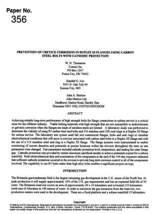
  • 10. Figure 4. View of second flange face showing Dupkx ourrent sensor 8 and referenceeleetrode E2. &)o ‘T .:,A-----JCP Off + ! I 1 I -----------------------.—------------..............----[.-..-.1-----——+...-—.. 4 ‘ij —......6 121CI ~ 21c~ 4 C~24 ! ..-.-.....-....Q- = * ““; I I .—.......-......+.—................... ‘. ~.. . . ........ ‘~~ ‘------ l’e - y /....... t.. . .... !...-..-’ ‘A~:= ~ . ..... ......... —.— : / % Gbp Sea 1 I “ ‘-/----- Air I ected o 20 40 60 se 140 lao I&l Expoeure7Le (c&” m r_ El BdtCr8uice . E21=lagecrevice ... Remde Fkmge Potdial~ Figure 5. Potential data for the 164 days exposure. GabrielOnyeuka-InvoiceINV-980187-G4T2C3,downloadedon10/20/20155:17AM-Single-userlicenseonly,copying/networkingprohibited.
  • 11. 500 400 II I-L I 44 24 C ,---’-+ Y–-”’-% s —-.= ?Air Injected I t I 1 1 I I 1 1 1 1 1 1 I I i t 1 1 i O 10 20 30 40 50 60 70 80 90 100 110 120 130 140 150 160 170 180 190 200 Exposure Time (days) I w Steel-2 + Steel-3 A Duplex+ _ Du@t3x-8 .. SsRing-9 ] Figure 6. Current density data for 164 days exposure, 400 0 -100 * Steel-2 + Steel-4 A Duplex* Duplex-7 I :.........................= :“””-””””””””””-”””””””””-< ‘ ..-–-,.. ........ -----------------t------------------------‘------------------------‘---------------I.~. ‘“””””””””””””””““”””””””””””””””A% ———— ___ Ak- On---p k-cpfl+ CP Or b I o 1 2 3 4 5 6 7 Exposure Time (days) Figure 7. Expanded view of current density data for first 8 days only GabrielOnyeuka-InvoiceINV-980187-G4T2C3,downloadedon10/20/20155:17AM-Single-userlicenseonly,copying/networkingprohibited.
  • 12. Figtue8. Top- TestfIange @ernsa%er164daysexposmc. -tbembberhosesused tosealofflheinside flanges on day 123 and the uniform calcareous deposit coverage. BottaIn-Di sassembled flanges and bolts. Note the uniform calcareous deposits on the bolts and insi flange faces. of de the the GabrielOnyeuka-InvoiceINV-980187-G4T2C3,downloadedon10/20/20155:17AM-Single-userlicenseonly,copying/networkingprohibited.
  • 13. F&Ine9. Top-(%smviewo ftheboltsf iomtbcfbtfkgc. Hm-Vlwof*~ti hk@&Wti~*) drn&tiflmgef~c~t Note the two currentsensing plugs electrkally isolated by epoxy. GabrielOnyeuka-InvoiceINV-980187-G4T2C3,downloadedon10/20/20155:17AM-Single-userlicenseonly,copying/networkingprohibited.
  • 14. Figure 10. Viewoffirstflan geiioeandcat odsoairing.Notecalcmws - insi& bolthole!% GabrielOnyeuka-InvoiceINV-980187-G4T2C3,downloadedon10/20/20155:17AM-Single-userlicenseonly,copying/networkingprohibited.
  • 15. Figpre 11. Top- Seeondflangewith isolated316 SS sealringin phiee. Black lead wire eonneets the seal fig (current sensor 9)tothe shorting andzero -~~-. Bottom -View ofseairing exposedsurfiwe. Acti-tidb*oftil-w=kRwti,d all but a 30 mm stripwas coveredwith black electricaltape. GabrielOnyeuka-InvoiceINV-980187-G4T2C3,downloadedon10/20/20155:17AM-Single-userlicenseonly,copying/networkingprohibited.
  • 16. l?iguIe12. 1301tontheri@twas immemedrnthe~~ASTM~ fm48heurs. NoteircQcixideproducts ontheboltimi inlhejaras cOmpuedtotk fhngebdtexposedfm 144daysun&r CP. GabrielOnyeuka-InvoiceINV-980187-G4T2C3,downloadedon10/20/20155:17AM-Single-userlicenseonly,copying/networkingprohibited.