SlideShare une entreprise Scribd logo
1  sur  11
Télécharger pour lire hors ligne
International Journal Of Computational Engineering Research (ijceronline.com) Vol. 3 Issue. 12

Design and Analysis of Industrial Helmet
1
1,2

Anil Kumar. K, 2Y. Suresh babu M.Tech

Department of Mechanical Engineering, Rajiv Gandhi Memorial College of Engineering & Technology,
Affiliated to J.N.T.University Anantapur, Nandyal,

ABSTRACT
All helmets attempt to protect the user’s head by absorbing mechanical energy and protecting
against penetration. Their structure and protective capacity are altered in high-energy impacts. Beside
their energy-absorption capability, their volume and weight are also important issues, since higher
volume and weight increase the injury risk for the user’s head and neck. Every year many workers are
killed or seriously injured in the construction industry as a result of head injuries. Wearing an
appropriate safety helmet significantly reduces the risk of injury or even death. Protective headwear
could save your life.
At present strength of the helmet using industry is less due to improper filling of material,
uneven pressure distribution and blow holes. The aim of the project is to increase the strength of
industrial helmet by making the modify material in existing one.
In order to achieve the objective of the project, the work is carried out in three stages.
In the first stage a parametric model is designed by using 3D modeling module in ProEngineer software. After designing the helmet, mould flow analysis is carried out on helmet by using
plastic advisor which is a module in pro/E. Mould flow analysis is used for finding material filling,
pressure distribution, air traps, and weld lines during the injection molding process at constant
pressure and different temperature ranges.
In the second stage, after completion of the mould flow analysis impact analysis is done on industrial
helmet by using COSMOS software for the three different type materials from different heights.

I.

INTRODUCTION

1.1 Introduction to Helmet
A helmet is a form of protective gear worn on the head to protect it from Injuries. Ceremonial or
symbolic helmets (e.g., English policeman's helmet) without protective function are sometimes used. The oldest
known use of helmets was by Assyrian soldiers in 900BC, who wore thick leather or bronze helmets to protect
the head from blunt object and sword blows and arrow strikes in combat. Soldiers still wear helmets, now often
made from lightweight plastic materials.

Figure 1.1 original model of industrial helmet
In civilian life, helmets are used for recreational activities and sports (e.g., jockeys in horse racing,
American football, ice hockey, cricket, and rock climbing); dangerous work activities (e.g., construction,
mining, riot police); and transportation. (e.g., Motorcycle helmets and bicycle helmets). Since the 1990s, most
helmets are made from resin or plastic, which may be reinforced with fibers such as aramids.

||Issn 2250-3005 ||

||December||2013||

Page 48
Design and analysis of industrial helmet
All helmets attempt to protect the user's head by absorbing mechanical energy and protecting against
penetration. Their structure and protective capacity are altered in high-energy impacts. Beside their energyabsorption capability, their volume and weight are also important issues, since higher volume and weight
increase the injury risk for the user's head and neck. Anatomical helmets adapted to the inner head structure
were invented by neurosurgeons at the end of the 20th century.
Helmets used for different purposes have different designs. For example, a bicycle helmet must protect
against blunt impact forces from the wearer's head striking the road. A helmet designed for rock climbing must
protect against heavy impact, and against objects such as small rocks and climbing equipment falling from
above. Practical concerns also dictate helmet design: a bicycling helmet should be aerodynamic in shape and
well ventilated, while a rock climbing helmet must be lightweight and small so that it does not interfere with
climbing.
Some helmets have other protective elements attached to them, such as a face visors or goggles or a
face cage, and ear plugs and other forms of protective headgear, and a communications system. Sports helmets
may have an integrated metal face protector (face cage).

II.

LITERATURE SURVEY

The literature towards the design methodologies, analysis techniques proposed by different authors is
collected and presented in the subsequent paragraphs.
Franklin, Glen A.
The purpose of this study was to identify the impact of motorcycle helmet use on patient outcomes and
cost of hospitalization, in a state with a mandatory helmet law.
Patients admitted after motorcycle crashes from July 1996 to October 2000 were reviewed, including
demographics, Injury Severity Score, length of stay, injuries, outcome, helmet use, hospital cost data, and
insurance information. Statistical analysis was performed comparing helmeted to un helmeted patients using
analysis of variance, Student's test, and regression analysis.
Admitted 216 patients, 174 wore helmets and 42 did not. Injury Severity Score correlated with both
length of stay and cost of hospitalization. Mortality was not significantly different in either group. Failure to
wear a helmet significantly increased incidence of head injuries (Student's t test, p < 0.02), but not other injuries.
Helmet use decreased mean cost of hospitalization by more than $6,000 per patient.
Failure to wear a helmet adds to the financial burden created by motorcycle-related injuries.
Therefore, individuals who do not wear helmets should pay higher insurance premiums.
G M Ginsberg and D S Silverberg
Legislation requiring bicyclists to wear helmets in Israel will, over a helmet's 5-year duration
(assuming 85% compliancy, 83.2% helmet efficiency for morbidity, and 70% helmet efficiency for mortality),
save approximately 57 lives and result in approximately 2544 fewer hospitalizations; 13,355 and 26,634 fewer
emergency room and ambulatory visits, respectively; and 832 and 115 fewer short-term and long-term
rehabilitation cases, respectively. Total benefits ($60.7 million) from reductions in health service use ($44.2
million), work absences ($7.5 million), and mortality ($8.9 million) would exceed program costs ($20.1
million), resulting in a benefit-cost ratio of 3.01:1.
Syrotuik, Daniel G. Reid, David C.
There is lack of consensus among pre-hospital personnel (athletic therapists, paramedics, sport
physiotherapists) concerning specific aspects of initial care and assessment of injured athletes presenting signs
and symptoms of a cervical spine injury (CSI).
In instances of serious injury involving the head and/or spine, complicated by altered levels of consciousness,
protective equipment such as helmets and shoulder pads may provide a hindrance to prompt, safe, and efficient management.
Specifically, there is disagreement concerning the need or advisability of removing protective head gear, as in the case of
football and hockey athletes. Using the technique of fluoroscopy, the cervical spine displacement of 21 male football and
hockey athletes was determined while wearing protective shoulder pads and protective head equipment at the following
times (a) during helmet removal, (b) during cervical collar application, and (c) as the helmetless head was allowed to rest.

||Issn 2250-3005 ||

||December||2013||

Page 49
Design and analysis of industrial helmet
Mohan J. Edirisinghe, Heidi M. Shaw and Katherine L. Tomkins
The yield stress of seven A16.SG alumina suspensions was estimated using shear stress-shear rate data
measured at the processing temperature. Five of these were processed using a high molecular weight
polypropylene binder system but each have a different %vol. of ceramic. The two other formulations contain a
low molecular weight alcohol as the major binder. The relative viscosities of the A16.SG aluminapolypropylene compositions were used in an extended form of the Eilers equation to evaluate Vmax, the
maximum volume fraction of ceramic. The relative viscosities of three other alumina powders processed using
the same polypropylene binder system were also investigated using the same equation in order to assess the
effect of particle characteristics on Vmax.

III.

PLASTICS

A material consisting of very large molecules characterized by light weight, high corrosion resistance,
high strength-to-weight ratios, and low melting points. Most plastics are easily shaped or formed.
3.1 Thermoplastic:
A thermoplastic, or thermo softening plastic, is a polymer that becomes pliable or moldable above a specific
temperature, and returns to a solid state upon cooling. [1][2] Most thermoplastics have a high molecular weight.
The polymer chains associate through intermolecular, which permit thermoplastics to be remolded because the
intermolecular interactions increase upon cooling and restore the bulk properties. In this way, thermoplastics
differ from thermosetting polymers, which form irreversible bonds during the curing process. Thermo sets often
do not melt, but break down and do not reform upon cooling
3.1.1Types of Thermoplastic:
Acetal
Acrylics
Acrylonitrile-Butadiene-Styrene
Nylon
Polyamide- imide etc
3.2 Acrylonitrile butadiene styrene (ABS)
ABS is a common thermoplastic. Its glass transition temperature is approximately 105 °C (221
°F).[1] ABS is amorphous and therefore has no true melting point.
ABS is a terpolymer made by polymerizing styrene and acrylonitrile in the presence ofpolybutadiene.
The proportions can vary from 15 to 35% acrylonitrile, 5 to 30% butadiene and 40 to 60% styrene. The result is
a long chain of poly butadiene criss-crossed with shorter chains of poly(styrene-co-acrylonitrile).
The nitrile groups from neighboring chains, being polar, attract each other and bind the chains together, making
ABS stronger than pure polystyrene. The styrene gives the plastic a shiny, impervious surface. The butadiene,
a rubbery substance, provides resilience even at low temperatures. For the majority of applications, ABS can be
used between −20 and 80 °C (−4 and 176 °F) as its mechanical properties vary with temperature. [2] The
properties are created by rubber toughening, where fine particles of elastomer are distributed throughout the
rigid matrix.
3.3 Impact grade Acrylonitrile butadiene styrene (ABS)
Medium high Impact grade ABS is a common thermoplastic. Its glass transition temperature is
approximately 105 °C (221 °F).[1] ABS is amorphous and therefore has no true melting point.
ABS is a terpolymer made by polymerizing styrene and acrylonitrile in the presence ofpolybutadiene. The
proportions can vary from 15 to 35% acrylonitrile, 25 to 50% butadiene and 30 to 50% styrene. The result is a
long chain of poly butadiene criss-crossed with shorter chains of poly(styrene-co-acrylonitrile).
The nitrile groups from neighboring chains, being polar, attract each other and bind the chains together, making
ABS stronger than pure polystyrene. If increasing of butadiene the impact grade ABS plastic more stronger than
the ABS plastic. The styrene gives the plastic a shiny, impervious surface. The butadiene, a rubbery substance,
provides resilience even at low temperatures. For the majority of applications, ABS can be used between
−25 and 90 °C (−3 and 196 °F) as its mechanical properties vary with temperature. [2] The properties are created
by rubber toughening, where fine particles of elastomer are distributed throughout the rigid matrix
3.4 Nylon 4-6 (polyamide):
The name "nylons" refers to the group of plastics known as polyamides. Nylons are typified by amide
groups (CONH) and encompass a range of material types (e.g. Nylon 6,6; Nylon 6,12; Nylon 4,6; Nylon 6;
Nylon 12 etc.), providing an extremely broad range of available properties. Nylon is used in the production of
film and fiber, but is also available as a moulding compound.
||Issn 2250-3005 ||

||December||2013||

Page 50
Design and analysis of industrial helmet
Nylon is formed by two methods. Dual numbers arise from the first, a condensation reaction between
diamines and dibasic acids produces a nylon salt. The first number of the nylon type refers to the number of
carbon atoms in the diamine, the second number is the quantity in the acid(e.g. nylon 6,12)
The second process involves opening up a monomer containing both amine and acid groups known as a
lactam ring. The nylon identity is based on the number of atoms in the lactam monomer (e.g. nylon 4-6 or nylon
12 etc).

IV.

MODELING AND MOULD FLOW ANALYSIS OF HELMET
Figure 4.1 2D Diagram of the industrial helmet

4.1 Design and manufacturing procedure of helmet
By using the fundamental abilities of the software with regards to the single data source Principle, it
provides a rich set of tools in the manufacturing environment in the form of tooling design and simulated CNC
machining and output. Tooling options cover specialty tools for molding, die-casting and progressive tooling
design.
4.2 Different Modules in Pro/Engineer
1. Part Design
2. Assembly
3. Drawing
4. Sheet metal
5. Mould Design
6. Manufacturing
4.3 Model of Industrial Helmet
Industrial helmet is model by using Pro/E software, Figure 4.2, Figure 4.3 & Figure 4.4 gives the
detailed explanation of the helmet modeled in Pro/E software

||Issn 2250-3005 ||

||December||2013||

Page 51
Design and analysis of industrial helmet

Figure 4.2 First Wire Frame Model

Figure 4.3 Surface Part

4.4 Plastic flow analysis
The Flow Analysis summary page gives an overview of the model's analysis, including information
about actual injection time and pressure and whether weld lines and air traps are present. In addition, the dialog
uses the Confidence of Fill result to assess the mould ability of the part. Figure 3.4 gives the information about
the plastic flow analysis

Figure 4.4 Solid model of the Helmet
4.5 Fill Time
This result shows the flow path of the plastic through the part by plotting contours which join regions
filling at the same time. These contours are displayed in a range of colors from red, to indicate the first region to
fill, through to blue to indicate the last region to fill. A short shot is a part of the model that did not fill, and will
be displayed as translucent. By plotting these contours in time sequence, the impression is given of plastic
actually flowing into the mould. Figure 3.5explains the fill time required for the helmet mould.

Figure 4.5 Fill time of Helmet
4.6 Confidence of Fill
The confidence of fill result displays the probability of a region within the cavity filling with plastic at
conventional injection molding conditions. This result is derived from the pressure and temperature results.
Figure 3.6 explains the confidence fill

||Issn 2250-3005 ||

||December||2013||

Page 52
Design and analysis of industrial helmet

Figure 4.6 Confidence of fill of helmet
4.7 Quality Analysis
The Quality display is derived from combinations of the five results listed below. These five results are
each divided into ranges - unacceptable (red), acceptable (yellow) and preferred (green). The five results are:
a)
b)
c)
d)
e)

flow front temperature
pressure drop
cooling time
shear rate
shear stress

For each area of the cavity, the five results are evaluated. If all five results in an area are acceptable, the
area is green. If there is at least one unacceptable result, the area is red. If there are both acceptable and preferred
results, the area is yellow.
1. An area of the Quality result is green if all of these cases are true:
The flow front temperature (T) is between the minimum (Tmin) and maximum (Tmax) recommended
temperatures for the material in the material database.

Tmin < T < Tmax

The pressure drop (Pdrop) is in the range between 0% and 80% of the maximum injection pressure (Pmax), as
set in the Processing Conditions Tab of the Molding Parameters dialog.
The cooling time (t) is less than 1.5 times the average cooling time for the part (tav)

Pdrop < (0.8Pmax)
t < 1.5tav

2. One of these conditions is true: An area of the Quality result is yellow if none of the red conditions is true, and at least.
The flow front temperature (T) is between the minimum (Tmin), recommended temperature for the Tmin < T < (T max + 5°C)
material and a value 5°C above the maximum (Tmax), recommended temperature for the material.
The pressure drop (Pdrop) lies in the range between 80% and 100% of the maximum injection
pressure (Pmax), as set in Processing Conditions Tab of the Molding Parameters dialog.
The cooling time (t) is between 1.5 and 5 times the average cooling time for the part.

(0.8Pmax) < Pdrop < Pmax
1.5tav < t < 5tav

3. An area of the Quality result is red if at least one of these cases is true:
The flow front temperature (T) is more than 5°C above the maximum
Maximum recommended temperature for material (Tmax)
The pressure drop (Pdrop) is greater than or equal to the maximum injection pressure (Pmax), as set in
Processing Conditions Tab of the Molding Parameters dialog.
The cooling time (t) is more than 5 times above the average cooling time for the part (tav).

T > (T max + 5°C)

Pdrop >= Pmax
t > 5tav

4.8 Important information about mould flow analysis
In this chapter mould flow analysis of helmets can be studied and also plastic flow analysis, filling time
of helmets, pressure drop in helmet, injection pressure in helmet, flow front temperature and quality of helmet
can be analyzed. By using this process manufacture of industrial helmet can be done without any failures.

||Issn 2250-3005 ||

||December||2013||

Page 53
Design and analysis of industrial helmet
The analysis results herein are believed to be reliable but are not to be construed as providing a
warranty, including any warranty of merchantability or fitness for purpose, or representation for which Mould
flow Corporation assumes legal responsibility. Users should undertake sufficient verification and testing to
determine the suitability for their own particular purpose of any information presented herein. Nothing herein is
to be taken as permission, inducement, or recommendation by Mould flow Corporation to practice any patented
invention without a license or in any way infringe upon the intellectual property rights of any other party.

V.

ANALYSIS OF THE HELMET BY USING COSMOS SOFTWARE

5.1 Analysis Steps
Complete analysis study by performing the following steps:
a)
b)

Create a study defining its analysis type and options.
If needed, define parameters of your study.

Parameters could be a model dimension, a material property, a force value, or any other entity that you
want to investigate its impact on the design
5.2 Impact analysis of Nylon 4-6 plastic when dropped from 2000m height
Properties of Nylon 4-6
Model Reference

Properties
Name:
Model type:
Default failure
criterion:
Yield strength:
Tensile strength:
Elastic modulus:
Poisson's ratio:
Mass density:
Shear modulus:

Default (4)
Linear Elastic Isotropic
Max von Mises Stress
2.5e+008 N/m^2
3e+007 N/m^2
1.6e+010 N/m^2
0.394
1400 kg/m^3
3.189e+008 N/m^2

Table 5.1 volumetric properties of helmet

Fig: solid mesh of helmet

||Issn 2250-3005 ||

||December||2013||

Page 54
Design and analysis of industrial helmet
5.9.4 Results of Stresses developed in the helmet dropped from 2000mm height

Discussion: In the given above Figure 5.28 the blue color indicates the minimum level of strain and the red
color indicates the maximum level of strain on helmet.
5.9.4

Results of displacement developed in the helmet dropped from 2000mm height

5.3 volumetric properties

||Issn 2250-3005 ||

||December||2013||

Page 55
Design and analysis of industrial helmet
5.9.5 Results of Displacement developed in the helmet dropped from 2000mm height.

5.9.5 Results of Strain developed in the helmet dropped from 2000mm height.
Name

Type

Min

Max

Strain1

ESTRN: Equivalent Strain

3.67835e-019

0.00442024

Element: 119510

Element: 119409

Figure:5.30 Results of Strains developed in the helmet

Discussion:

In the given above Figure 5.30 the blue color indicates the minimum level of strain and the red

color indicates the maximum level of strain on helmet.

||Issn 2250-3005 ||

||December||2013||

Page 56
Design and analysis of industrial helmet
VI. RESULT ANALYSIS
Impact analysis is carried out on the existing designed helmets by using COSMOS software and the
results are tabulated as following
6.1.1 ABS Plastic
DISTANCES (mm)

2

DISPLACEMENT (mm)

STRAIN

FOS

0.0309706

0.00746974

1.89

2000

STRESS (N/mm )
17.1164

3000

21.1292

0.0382015

0.00922569

1.52

4000

23.8155

0.044087

0.0104911

1.25

DISPLACEMENT (mm)

STRAIN

FOS

0.0310221
0.0382672
0.0440759

0.00710183
0.00877044
0.0100622

1.90
1.54
1.35

DISPLACEMENT (MM)

STRAIN

FOS

2000mm

STRESS (N/MM )
89.8

-3

2.78

3000mm

97.98

4.027e

6.1.2 Impact ABS Plastic
DISTANCES (mm)
2000
3000
4000

2

STRESS (N/mm )
23.6628
29.2154
33.3442

6.1.2 Impact ABS Plastic
DISTANCES (mm)

4000mm

2

113.7

-2

6.200e
-2
-2

4.667e

4.420e
-2

2.653e
-3

5.355e

2.55
2.22

Stress produced in Nylon 4-6 plastic helmet is more than stresses produced in impact ABS plastic and
ABS plastic helmet for different heights. It indicates that the resistance against the load per unit area, factor of
safety is more, and with standing capacity of Nylon 4-6 plastic is more.
From the results it is proved that displacement produced in Nylon 4-6 plastic helmet is more than
displacement produced in ABS plastic and impact ABS plastic helmet for different heights. It shows that the
displacement of helmet cannot be altered to high and the impact of load on helmet is less.
Volumetric Strain produced in Nylon 4-6 plastic helmet is less than strain produced in ABS plastic and
impact ABS plastic helmet for different heights, which gives more rigidity to the human neck from impact
loads.
In this chapter, it is found that the Nylon 4-6 plastic is good instead of ABS plastic and impact ABS
plastic helmet by using based on the above results.
ACKNOWLEDGEMENT
It is my privilege to express my profound gratitude and thanks to my guide Y. Suresh Babu, M.Tech.
Asst, Professor in Mechanical Engineering, R.G.M College of Engineering and Technology, for his valuable
guidance and encouragement throughout the course of this project work. Without his enthusiastic
encouragement and support this work would most probably not have been completed.
I express my profound sense of gratitude and indebtedness to overall project work guide,
Dr: S.
Altaf Hussain Professor, Department of Mechanical Engineering, Rajiv Gandhi Memorial College of
Engineering & Technology, Nandyal for his valuable guidance and suggestion to do my project
I earnestly express my deep sense gratitude and appreatiation to Dr. K.THIRUPATHI REDDY,
M.Tech, Ph.D., Professor and Head of the Department of Mechanical Engineering, R.G.M College of
Engineering and Technology for providing all the lab facilities of Mechanical Engineering department and all
kinds of support during the course of this study.
I take this opportunity to express my sincere thanks and indebtness to Dr. T. JAYA CHANDRA
PRASAD, M.Tech, Ph.D,. Principal, R.G.M College of Engineering and Technology, Nandyal for cooperation
throughout this project.
My special thanks to our chairman Dr. M. SANTHI RAMUDU chairman of the college for providing
all amenities to complete our project work.
My thanks to Smt. H. Deepthi, Managing director of Win Will Technology for co-operation to
complete this project work.
I would like express my heartful thanks to each and every teaching and non- teaching staff members
of mechanical engineering department.
Finally I thankful to one and all who gave their whole hearted co-operation to complete this project work.
||Issn 2250-3005 ||

||December||2013||

Page 57
Design and analysis of industrial helmet

BIBLIOGRAPHY
[1.]
[2.]
[3.]
[4.]
[5.]
[6.]
[7.]
[8.]
[9.]
[10.]
[11.]
[12.]
[13.]
[14.]
[15.]
[16.]
[17.]
[18.]
[19.]
[20.]
[21.]
[22.]
[23.]
[24.]

Bair.s and Winer.W.O, “A technique for measuring helmet and follower skidding on automotive vehicals”, Proceedings of the
17th Leeds-Lyon symposium of Tribology, September 4-7, 1990, Paper 6, tribology series 18, 1991, Elsevier.
Bas.H et al., “A new test apparatus for the tribological behaviour of analysis”, Experimental techniques, September/October
2003, pp 28-32.
Bassani.R et al., “Experimental investigation of transient and thermal effects on lubricated non-conformal contacts”, Tribotest,
2007, Vol. 13, pp 183-194.
Bayrakceken.H et al., “Fracture analysis of a helmet made from impact abs plastic”, Original research article engineering failure
analysis, December 2006, Vol. 13, Issue 8, pp 1240-1245
Belofsky, H., Plastics: Product Design and Process Engineering, Hanser Publishers, Munich, Vienna, New York, 1995.
Cardona.A et al., “injection moulding process”, 2002, vol. 7, pp 285-305
Chakraborty.J and Dhande.S.G, “Kinematics and geometry of planar and spatial mechanisms”, 1977, (John Wiley, New York).
Design data book: P.S.G.College of Technology (Kalaikathir achchagam), “Aluminum Properties” edition: 2007.
Gangopadhya.A et al., “Evaluation of tribological performance of ceramic roller follower”, 1990, SAE 900401.
Greenham.G and Catterley.T, “scoter helmet: (Manganese Bronze powder metals Group, Ipswich, England)”, Powder
metallurgy, 1991, Vol. 34, No 2, pp 119-125.
Injection mould design: R.G.W. PYE (East-West press Pvt. Ltd), Edition2000 pp-2.
Lin.Y and Pisano.A, “Three-dimensional dynamic simulation of football helmet”, 1990, Trans. ASME, J.Mech. Des., Vol.112,
pp 529-537
Lens.E and Nigro.N, “Optimal design of helmet”, Multibody system dynamics, 2002, issue 7, pp 285-305.
Levent cenk kumrouglu, “Mechanical properties of abs plastic helmet: Experimental and computer aided evaluation”, Original
research article materials and design, April 2009, Vol. 30, Issue 4, pp 927-938.
M.E. Gomes, A.S. Ribeiro, P.B. Malafaya, R.L. Reis and A.M. Cunha Department of
Polymer Engineering, University of
Minho, Campus de Gualtar, 4710-057 Braga, Portugal.
Müller, P. Kauranen , A. von Ganski and B. Hell SGL Technologies GmbH, VTT Technical Research, Centre of Finland.
Mohan J. Edirisinghe, Heidi M. Shaw and Katherine L. Tomkins Department of Materials Technology, Brunel University,
Uxbridge, Middx, UK, UB8 3PH.
Norton.R.L, “The helmet design and manufacturing handbook”, The Industrial Press, New York, 2002.
Per Lindholm, et al., “Characterisation a industrial helmet follower system in a construction field”, Original research article,
October 2003, Vol. 254, Issue 11, pp 1199-1207.
Progelhof, R.C. and J.L. Throne, "Polymer Engineering Principles: Properties, Processes,
and Tests for Design", Hanser Publishers, New York, 1993.
Prinsen, Rosanne K. E. M.Sc.; Syrotuik, Daniel G. Ph.D.; Reid, David C. M.D.
W. D. Brouwer, , E. C. F. C. van Herpt and M. Labordus Centre of Lightweight Structures TUD-TNO, Kluyverweg 1, Delft 2629
HS, The Netherlands.
Zhu.G and Taylor.C.M., “Tribological analysis and design of a modern bicycle helmet follower, Wiltshire, UK: polymer
Engineering Publishing, 2001, ISBN 1-86058-203-6.

||Issn 2250-3005 ||

||December||2013||

Page 58

Contenu connexe

Similaire à H021201048058

IRJET- Design and Analysis of Aluminum Honeycomb Structure for Helmet Shell
IRJET-  	  Design and Analysis of Aluminum Honeycomb Structure for Helmet ShellIRJET-  	  Design and Analysis of Aluminum Honeycomb Structure for Helmet Shell
IRJET- Design and Analysis of Aluminum Honeycomb Structure for Helmet ShellIRJET Journal
 
The Unseen Guardian_ Workplace Safety with Safety Helmets.pdf
The Unseen Guardian_ Workplace Safety with Safety Helmets.pdfThe Unseen Guardian_ Workplace Safety with Safety Helmets.pdf
The Unseen Guardian_ Workplace Safety with Safety Helmets.pdfJohnson Trading
 
The Unseen Guardian_ Workplace Safety with Safety Helmets.pptx
The Unseen Guardian_ Workplace Safety with Safety Helmets.pptxThe Unseen Guardian_ Workplace Safety with Safety Helmets.pptx
The Unseen Guardian_ Workplace Safety with Safety Helmets.pptxJohnson Trading
 
Case study on Helmet
Case study on HelmetCase study on Helmet
Case study on HelmetDheirya Joshi
 
Bump Caps vs Hard Hats in Workplace Safety.pptx
Bump Caps vs Hard Hats in Workplace Safety.pptxBump Caps vs Hard Hats in Workplace Safety.pptx
Bump Caps vs Hard Hats in Workplace Safety.pptxGarment Printing
 
Composite pressure vessels
Composite pressure vesselsComposite pressure vessels
Composite pressure vesselseSAT Journals
 
Bulletproof vest with ceramic insert (1)
Bulletproof vest with ceramic insert (1)Bulletproof vest with ceramic insert (1)
Bulletproof vest with ceramic insert (1)FaisalHusainiBadri
 
Bulletproof vest with ceramic insert
Bulletproof vest with ceramic insert Bulletproof vest with ceramic insert
Bulletproof vest with ceramic insert FaizZais
 
Independent High School STEM Project Paper
Independent High School STEM Project PaperIndependent High School STEM Project Paper
Independent High School STEM Project PaperRISHI MAKKAR
 
Basics of Body Armour Technology.pdf
Basics of Body Armour Technology.pdfBasics of Body Armour Technology.pdf
Basics of Body Armour Technology.pdfmkuofficial1
 
Characterization of Hydrophobic Nanoporous Particle Liquids for Energy Absorp...
Characterization of Hydrophobic Nanoporous Particle Liquids for Energy Absorp...Characterization of Hydrophobic Nanoporous Particle Liquids for Energy Absorp...
Characterization of Hydrophobic Nanoporous Particle Liquids for Energy Absorp...Yi Hsu
 
Study of Influence of Different Parameters of Head- Restraints on Energy Abso...
Study of Influence of Different Parameters of Head- Restraints on Energy Abso...Study of Influence of Different Parameters of Head- Restraints on Energy Abso...
Study of Influence of Different Parameters of Head- Restraints on Energy Abso...AM Publications
 
Towards A Safer Design of Helmets: Finite Element & Experimental Assessment
Towards A Safer Design of Helmets: Finite Element & Experimental AssessmentTowards A Safer Design of Helmets: Finite Element & Experimental Assessment
Towards A Safer Design of Helmets: Finite Element & Experimental AssessmentSari Kassar
 
Personal protective equipment
Personal protective equipmentPersonal protective equipment
Personal protective equipmentSibghatUllah50
 
IRJET- Study Analysis of Metal Bending in a Sheet Metal using Finite Elem...
IRJET-  	  Study Analysis of Metal Bending in a Sheet Metal using Finite Elem...IRJET-  	  Study Analysis of Metal Bending in a Sheet Metal using Finite Elem...
IRJET- Study Analysis of Metal Bending in a Sheet Metal using Finite Elem...IRJET Journal
 
BEHAVIOUR OF THE ROPES CONSTITUENTS UNDER THE ACTION OF RISK FACTORS THAT EXI...
BEHAVIOUR OF THE ROPES CONSTITUENTS UNDER THE ACTION OF RISK FACTORS THAT EXI...BEHAVIOUR OF THE ROPES CONSTITUENTS UNDER THE ACTION OF RISK FACTORS THAT EXI...
BEHAVIOUR OF THE ROPES CONSTITUENTS UNDER THE ACTION OF RISK FACTORS THAT EXI...IAEME Publication
 
Fatigue Analysis of Fuselage and Wing Joint
Fatigue Analysis of Fuselage and Wing JointFatigue Analysis of Fuselage and Wing Joint
Fatigue Analysis of Fuselage and Wing JointVemuri Saikrishna
 

Similaire à H021201048058 (20)

Ijmet 09 11_023
Ijmet 09 11_023Ijmet 09 11_023
Ijmet 09 11_023
 
IRJET- Design and Analysis of Aluminum Honeycomb Structure for Helmet Shell
IRJET-  	  Design and Analysis of Aluminum Honeycomb Structure for Helmet ShellIRJET-  	  Design and Analysis of Aluminum Honeycomb Structure for Helmet Shell
IRJET- Design and Analysis of Aluminum Honeycomb Structure for Helmet Shell
 
The Unseen Guardian_ Workplace Safety with Safety Helmets.pdf
The Unseen Guardian_ Workplace Safety with Safety Helmets.pdfThe Unseen Guardian_ Workplace Safety with Safety Helmets.pdf
The Unseen Guardian_ Workplace Safety with Safety Helmets.pdf
 
The Unseen Guardian_ Workplace Safety with Safety Helmets.pptx
The Unseen Guardian_ Workplace Safety with Safety Helmets.pptxThe Unseen Guardian_ Workplace Safety with Safety Helmets.pptx
The Unseen Guardian_ Workplace Safety with Safety Helmets.pptx
 
Case study on Helmet
Case study on HelmetCase study on Helmet
Case study on Helmet
 
Bump Caps vs Hard Hats in Workplace Safety.pptx
Bump Caps vs Hard Hats in Workplace Safety.pptxBump Caps vs Hard Hats in Workplace Safety.pptx
Bump Caps vs Hard Hats in Workplace Safety.pptx
 
Composite pressure vessels
Composite pressure vesselsComposite pressure vessels
Composite pressure vessels
 
Composite pressure vessels
Composite pressure vesselsComposite pressure vessels
Composite pressure vessels
 
Bulletproof vest with ceramic insert (1)
Bulletproof vest with ceramic insert (1)Bulletproof vest with ceramic insert (1)
Bulletproof vest with ceramic insert (1)
 
Bulletproof vest with ceramic insert
Bulletproof vest with ceramic insert Bulletproof vest with ceramic insert
Bulletproof vest with ceramic insert
 
Independent High School STEM Project Paper
Independent High School STEM Project PaperIndependent High School STEM Project Paper
Independent High School STEM Project Paper
 
Basics of Body Armour Technology.pdf
Basics of Body Armour Technology.pdfBasics of Body Armour Technology.pdf
Basics of Body Armour Technology.pdf
 
Characterization of Hydrophobic Nanoporous Particle Liquids for Energy Absorp...
Characterization of Hydrophobic Nanoporous Particle Liquids for Energy Absorp...Characterization of Hydrophobic Nanoporous Particle Liquids for Energy Absorp...
Characterization of Hydrophobic Nanoporous Particle Liquids for Energy Absorp...
 
Study of Influence of Different Parameters of Head- Restraints on Energy Abso...
Study of Influence of Different Parameters of Head- Restraints on Energy Abso...Study of Influence of Different Parameters of Head- Restraints on Energy Abso...
Study of Influence of Different Parameters of Head- Restraints on Energy Abso...
 
Ppe group ii assignment
Ppe  group ii  assignment Ppe  group ii  assignment
Ppe group ii assignment
 
Towards A Safer Design of Helmets: Finite Element & Experimental Assessment
Towards A Safer Design of Helmets: Finite Element & Experimental AssessmentTowards A Safer Design of Helmets: Finite Element & Experimental Assessment
Towards A Safer Design of Helmets: Finite Element & Experimental Assessment
 
Personal protective equipment
Personal protective equipmentPersonal protective equipment
Personal protective equipment
 
IRJET- Study Analysis of Metal Bending in a Sheet Metal using Finite Elem...
IRJET-  	  Study Analysis of Metal Bending in a Sheet Metal using Finite Elem...IRJET-  	  Study Analysis of Metal Bending in a Sheet Metal using Finite Elem...
IRJET- Study Analysis of Metal Bending in a Sheet Metal using Finite Elem...
 
BEHAVIOUR OF THE ROPES CONSTITUENTS UNDER THE ACTION OF RISK FACTORS THAT EXI...
BEHAVIOUR OF THE ROPES CONSTITUENTS UNDER THE ACTION OF RISK FACTORS THAT EXI...BEHAVIOUR OF THE ROPES CONSTITUENTS UNDER THE ACTION OF RISK FACTORS THAT EXI...
BEHAVIOUR OF THE ROPES CONSTITUENTS UNDER THE ACTION OF RISK FACTORS THAT EXI...
 
Fatigue Analysis of Fuselage and Wing Joint
Fatigue Analysis of Fuselage and Wing JointFatigue Analysis of Fuselage and Wing Joint
Fatigue Analysis of Fuselage and Wing Joint
 

Dernier

Artificial intelligence in cctv survelliance.pptx
Artificial intelligence in cctv survelliance.pptxArtificial intelligence in cctv survelliance.pptx
Artificial intelligence in cctv survelliance.pptxhariprasad279825
 
The Future of Software Development - Devin AI Innovative Approach.pdf
The Future of Software Development - Devin AI Innovative Approach.pdfThe Future of Software Development - Devin AI Innovative Approach.pdf
The Future of Software Development - Devin AI Innovative Approach.pdfSeasiaInfotech2
 
CloudStudio User manual (basic edition):
CloudStudio User manual (basic edition):CloudStudio User manual (basic edition):
CloudStudio User manual (basic edition):comworks
 
Integration and Automation in Practice: CI/CD in Mule Integration and Automat...
Integration and Automation in Practice: CI/CD in Mule Integration and Automat...Integration and Automation in Practice: CI/CD in Mule Integration and Automat...
Integration and Automation in Practice: CI/CD in Mule Integration and Automat...Patryk Bandurski
 
"Subclassing and Composition – A Pythonic Tour of Trade-Offs", Hynek Schlawack
"Subclassing and Composition – A Pythonic Tour of Trade-Offs", Hynek Schlawack"Subclassing and Composition – A Pythonic Tour of Trade-Offs", Hynek Schlawack
"Subclassing and Composition – A Pythonic Tour of Trade-Offs", Hynek SchlawackFwdays
 
Streamlining Python Development: A Guide to a Modern Project Setup
Streamlining Python Development: A Guide to a Modern Project SetupStreamlining Python Development: A Guide to a Modern Project Setup
Streamlining Python Development: A Guide to a Modern Project SetupFlorian Wilhelm
 
Advanced Test Driven-Development @ php[tek] 2024
Advanced Test Driven-Development @ php[tek] 2024Advanced Test Driven-Development @ php[tek] 2024
Advanced Test Driven-Development @ php[tek] 2024Scott Keck-Warren
 
Are Multi-Cloud and Serverless Good or Bad?
Are Multi-Cloud and Serverless Good or Bad?Are Multi-Cloud and Serverless Good or Bad?
Are Multi-Cloud and Serverless Good or Bad?Mattias Andersson
 
"Debugging python applications inside k8s environment", Andrii Soldatenko
"Debugging python applications inside k8s environment", Andrii Soldatenko"Debugging python applications inside k8s environment", Andrii Soldatenko
"Debugging python applications inside k8s environment", Andrii SoldatenkoFwdays
 
Kotlin Multiplatform & Compose Multiplatform - Starter kit for pragmatics
Kotlin Multiplatform & Compose Multiplatform - Starter kit for pragmaticsKotlin Multiplatform & Compose Multiplatform - Starter kit for pragmatics
Kotlin Multiplatform & Compose Multiplatform - Starter kit for pragmaticscarlostorres15106
 
WordPress Websites for Engineers: Elevate Your Brand
WordPress Websites for Engineers: Elevate Your BrandWordPress Websites for Engineers: Elevate Your Brand
WordPress Websites for Engineers: Elevate Your Brandgvaughan
 
Search Engine Optimization SEO PDF for 2024.pdf
Search Engine Optimization SEO PDF for 2024.pdfSearch Engine Optimization SEO PDF for 2024.pdf
Search Engine Optimization SEO PDF for 2024.pdfRankYa
 
SAP Build Work Zone - Overview L2-L3.pptx
SAP Build Work Zone - Overview L2-L3.pptxSAP Build Work Zone - Overview L2-L3.pptx
SAP Build Work Zone - Overview L2-L3.pptxNavinnSomaal
 
SIP trunking in Janus @ Kamailio World 2024
SIP trunking in Janus @ Kamailio World 2024SIP trunking in Janus @ Kamailio World 2024
SIP trunking in Janus @ Kamailio World 2024Lorenzo Miniero
 
"LLMs for Python Engineers: Advanced Data Analysis and Semantic Kernel",Oleks...
"LLMs for Python Engineers: Advanced Data Analysis and Semantic Kernel",Oleks..."LLMs for Python Engineers: Advanced Data Analysis and Semantic Kernel",Oleks...
"LLMs for Python Engineers: Advanced Data Analysis and Semantic Kernel",Oleks...Fwdays
 
Unraveling Multimodality with Large Language Models.pdf
Unraveling Multimodality with Large Language Models.pdfUnraveling Multimodality with Large Language Models.pdf
Unraveling Multimodality with Large Language Models.pdfAlex Barbosa Coqueiro
 
Gen AI in Business - Global Trends Report 2024.pdf
Gen AI in Business - Global Trends Report 2024.pdfGen AI in Business - Global Trends Report 2024.pdf
Gen AI in Business - Global Trends Report 2024.pdfAddepto
 
Vertex AI Gemini Prompt Engineering Tips
Vertex AI Gemini Prompt Engineering TipsVertex AI Gemini Prompt Engineering Tips
Vertex AI Gemini Prompt Engineering TipsMiki Katsuragi
 
Training state-of-the-art general text embedding
Training state-of-the-art general text embeddingTraining state-of-the-art general text embedding
Training state-of-the-art general text embeddingZilliz
 
My INSURER PTE LTD - Insurtech Innovation Award 2024
My INSURER PTE LTD - Insurtech Innovation Award 2024My INSURER PTE LTD - Insurtech Innovation Award 2024
My INSURER PTE LTD - Insurtech Innovation Award 2024The Digital Insurer
 

Dernier (20)

Artificial intelligence in cctv survelliance.pptx
Artificial intelligence in cctv survelliance.pptxArtificial intelligence in cctv survelliance.pptx
Artificial intelligence in cctv survelliance.pptx
 
The Future of Software Development - Devin AI Innovative Approach.pdf
The Future of Software Development - Devin AI Innovative Approach.pdfThe Future of Software Development - Devin AI Innovative Approach.pdf
The Future of Software Development - Devin AI Innovative Approach.pdf
 
CloudStudio User manual (basic edition):
CloudStudio User manual (basic edition):CloudStudio User manual (basic edition):
CloudStudio User manual (basic edition):
 
Integration and Automation in Practice: CI/CD in Mule Integration and Automat...
Integration and Automation in Practice: CI/CD in Mule Integration and Automat...Integration and Automation in Practice: CI/CD in Mule Integration and Automat...
Integration and Automation in Practice: CI/CD in Mule Integration and Automat...
 
"Subclassing and Composition – A Pythonic Tour of Trade-Offs", Hynek Schlawack
"Subclassing and Composition – A Pythonic Tour of Trade-Offs", Hynek Schlawack"Subclassing and Composition – A Pythonic Tour of Trade-Offs", Hynek Schlawack
"Subclassing and Composition – A Pythonic Tour of Trade-Offs", Hynek Schlawack
 
Streamlining Python Development: A Guide to a Modern Project Setup
Streamlining Python Development: A Guide to a Modern Project SetupStreamlining Python Development: A Guide to a Modern Project Setup
Streamlining Python Development: A Guide to a Modern Project Setup
 
Advanced Test Driven-Development @ php[tek] 2024
Advanced Test Driven-Development @ php[tek] 2024Advanced Test Driven-Development @ php[tek] 2024
Advanced Test Driven-Development @ php[tek] 2024
 
Are Multi-Cloud and Serverless Good or Bad?
Are Multi-Cloud and Serverless Good or Bad?Are Multi-Cloud and Serverless Good or Bad?
Are Multi-Cloud and Serverless Good or Bad?
 
"Debugging python applications inside k8s environment", Andrii Soldatenko
"Debugging python applications inside k8s environment", Andrii Soldatenko"Debugging python applications inside k8s environment", Andrii Soldatenko
"Debugging python applications inside k8s environment", Andrii Soldatenko
 
Kotlin Multiplatform & Compose Multiplatform - Starter kit for pragmatics
Kotlin Multiplatform & Compose Multiplatform - Starter kit for pragmaticsKotlin Multiplatform & Compose Multiplatform - Starter kit for pragmatics
Kotlin Multiplatform & Compose Multiplatform - Starter kit for pragmatics
 
WordPress Websites for Engineers: Elevate Your Brand
WordPress Websites for Engineers: Elevate Your BrandWordPress Websites for Engineers: Elevate Your Brand
WordPress Websites for Engineers: Elevate Your Brand
 
Search Engine Optimization SEO PDF for 2024.pdf
Search Engine Optimization SEO PDF for 2024.pdfSearch Engine Optimization SEO PDF for 2024.pdf
Search Engine Optimization SEO PDF for 2024.pdf
 
SAP Build Work Zone - Overview L2-L3.pptx
SAP Build Work Zone - Overview L2-L3.pptxSAP Build Work Zone - Overview L2-L3.pptx
SAP Build Work Zone - Overview L2-L3.pptx
 
SIP trunking in Janus @ Kamailio World 2024
SIP trunking in Janus @ Kamailio World 2024SIP trunking in Janus @ Kamailio World 2024
SIP trunking in Janus @ Kamailio World 2024
 
"LLMs for Python Engineers: Advanced Data Analysis and Semantic Kernel",Oleks...
"LLMs for Python Engineers: Advanced Data Analysis and Semantic Kernel",Oleks..."LLMs for Python Engineers: Advanced Data Analysis and Semantic Kernel",Oleks...
"LLMs for Python Engineers: Advanced Data Analysis and Semantic Kernel",Oleks...
 
Unraveling Multimodality with Large Language Models.pdf
Unraveling Multimodality with Large Language Models.pdfUnraveling Multimodality with Large Language Models.pdf
Unraveling Multimodality with Large Language Models.pdf
 
Gen AI in Business - Global Trends Report 2024.pdf
Gen AI in Business - Global Trends Report 2024.pdfGen AI in Business - Global Trends Report 2024.pdf
Gen AI in Business - Global Trends Report 2024.pdf
 
Vertex AI Gemini Prompt Engineering Tips
Vertex AI Gemini Prompt Engineering TipsVertex AI Gemini Prompt Engineering Tips
Vertex AI Gemini Prompt Engineering Tips
 
Training state-of-the-art general text embedding
Training state-of-the-art general text embeddingTraining state-of-the-art general text embedding
Training state-of-the-art general text embedding
 
My INSURER PTE LTD - Insurtech Innovation Award 2024
My INSURER PTE LTD - Insurtech Innovation Award 2024My INSURER PTE LTD - Insurtech Innovation Award 2024
My INSURER PTE LTD - Insurtech Innovation Award 2024
 

H021201048058

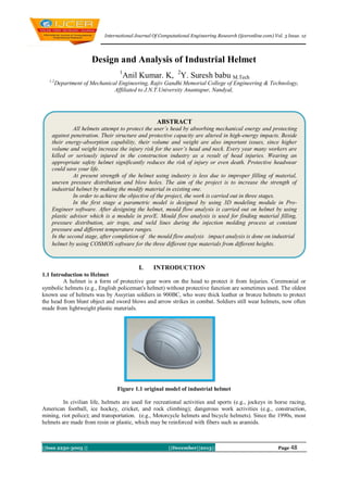
  • 1. International Journal Of Computational Engineering Research (ijceronline.com) Vol. 3 Issue. 12 Design and Analysis of Industrial Helmet 1 1,2 Anil Kumar. K, 2Y. Suresh babu M.Tech Department of Mechanical Engineering, Rajiv Gandhi Memorial College of Engineering & Technology, Affiliated to J.N.T.University Anantapur, Nandyal, ABSTRACT All helmets attempt to protect the user’s head by absorbing mechanical energy and protecting against penetration. Their structure and protective capacity are altered in high-energy impacts. Beside their energy-absorption capability, their volume and weight are also important issues, since higher volume and weight increase the injury risk for the user’s head and neck. Every year many workers are killed or seriously injured in the construction industry as a result of head injuries. Wearing an appropriate safety helmet significantly reduces the risk of injury or even death. Protective headwear could save your life. At present strength of the helmet using industry is less due to improper filling of material, uneven pressure distribution and blow holes. The aim of the project is to increase the strength of industrial helmet by making the modify material in existing one. In order to achieve the objective of the project, the work is carried out in three stages. In the first stage a parametric model is designed by using 3D modeling module in ProEngineer software. After designing the helmet, mould flow analysis is carried out on helmet by using plastic advisor which is a module in pro/E. Mould flow analysis is used for finding material filling, pressure distribution, air traps, and weld lines during the injection molding process at constant pressure and different temperature ranges. In the second stage, after completion of the mould flow analysis impact analysis is done on industrial helmet by using COSMOS software for the three different type materials from different heights. I. INTRODUCTION 1.1 Introduction to Helmet A helmet is a form of protective gear worn on the head to protect it from Injuries. Ceremonial or symbolic helmets (e.g., English policeman's helmet) without protective function are sometimes used. The oldest known use of helmets was by Assyrian soldiers in 900BC, who wore thick leather or bronze helmets to protect the head from blunt object and sword blows and arrow strikes in combat. Soldiers still wear helmets, now often made from lightweight plastic materials. Figure 1.1 original model of industrial helmet In civilian life, helmets are used for recreational activities and sports (e.g., jockeys in horse racing, American football, ice hockey, cricket, and rock climbing); dangerous work activities (e.g., construction, mining, riot police); and transportation. (e.g., Motorcycle helmets and bicycle helmets). Since the 1990s, most helmets are made from resin or plastic, which may be reinforced with fibers such as aramids. ||Issn 2250-3005 || ||December||2013|| Page 48
  • 2. Design and analysis of industrial helmet All helmets attempt to protect the user's head by absorbing mechanical energy and protecting against penetration. Their structure and protective capacity are altered in high-energy impacts. Beside their energyabsorption capability, their volume and weight are also important issues, since higher volume and weight increase the injury risk for the user's head and neck. Anatomical helmets adapted to the inner head structure were invented by neurosurgeons at the end of the 20th century. Helmets used for different purposes have different designs. For example, a bicycle helmet must protect against blunt impact forces from the wearer's head striking the road. A helmet designed for rock climbing must protect against heavy impact, and against objects such as small rocks and climbing equipment falling from above. Practical concerns also dictate helmet design: a bicycling helmet should be aerodynamic in shape and well ventilated, while a rock climbing helmet must be lightweight and small so that it does not interfere with climbing. Some helmets have other protective elements attached to them, such as a face visors or goggles or a face cage, and ear plugs and other forms of protective headgear, and a communications system. Sports helmets may have an integrated metal face protector (face cage). II. LITERATURE SURVEY The literature towards the design methodologies, analysis techniques proposed by different authors is collected and presented in the subsequent paragraphs. Franklin, Glen A. The purpose of this study was to identify the impact of motorcycle helmet use on patient outcomes and cost of hospitalization, in a state with a mandatory helmet law. Patients admitted after motorcycle crashes from July 1996 to October 2000 were reviewed, including demographics, Injury Severity Score, length of stay, injuries, outcome, helmet use, hospital cost data, and insurance information. Statistical analysis was performed comparing helmeted to un helmeted patients using analysis of variance, Student's test, and regression analysis. Admitted 216 patients, 174 wore helmets and 42 did not. Injury Severity Score correlated with both length of stay and cost of hospitalization. Mortality was not significantly different in either group. Failure to wear a helmet significantly increased incidence of head injuries (Student's t test, p < 0.02), but not other injuries. Helmet use decreased mean cost of hospitalization by more than $6,000 per patient. Failure to wear a helmet adds to the financial burden created by motorcycle-related injuries. Therefore, individuals who do not wear helmets should pay higher insurance premiums. G M Ginsberg and D S Silverberg Legislation requiring bicyclists to wear helmets in Israel will, over a helmet's 5-year duration (assuming 85% compliancy, 83.2% helmet efficiency for morbidity, and 70% helmet efficiency for mortality), save approximately 57 lives and result in approximately 2544 fewer hospitalizations; 13,355 and 26,634 fewer emergency room and ambulatory visits, respectively; and 832 and 115 fewer short-term and long-term rehabilitation cases, respectively. Total benefits ($60.7 million) from reductions in health service use ($44.2 million), work absences ($7.5 million), and mortality ($8.9 million) would exceed program costs ($20.1 million), resulting in a benefit-cost ratio of 3.01:1. Syrotuik, Daniel G. Reid, David C. There is lack of consensus among pre-hospital personnel (athletic therapists, paramedics, sport physiotherapists) concerning specific aspects of initial care and assessment of injured athletes presenting signs and symptoms of a cervical spine injury (CSI). In instances of serious injury involving the head and/or spine, complicated by altered levels of consciousness, protective equipment such as helmets and shoulder pads may provide a hindrance to prompt, safe, and efficient management. Specifically, there is disagreement concerning the need or advisability of removing protective head gear, as in the case of football and hockey athletes. Using the technique of fluoroscopy, the cervical spine displacement of 21 male football and hockey athletes was determined while wearing protective shoulder pads and protective head equipment at the following times (a) during helmet removal, (b) during cervical collar application, and (c) as the helmetless head was allowed to rest. ||Issn 2250-3005 || ||December||2013|| Page 49
  • 3. Design and analysis of industrial helmet Mohan J. Edirisinghe, Heidi M. Shaw and Katherine L. Tomkins The yield stress of seven A16.SG alumina suspensions was estimated using shear stress-shear rate data measured at the processing temperature. Five of these were processed using a high molecular weight polypropylene binder system but each have a different %vol. of ceramic. The two other formulations contain a low molecular weight alcohol as the major binder. The relative viscosities of the A16.SG aluminapolypropylene compositions were used in an extended form of the Eilers equation to evaluate Vmax, the maximum volume fraction of ceramic. The relative viscosities of three other alumina powders processed using the same polypropylene binder system were also investigated using the same equation in order to assess the effect of particle characteristics on Vmax. III. PLASTICS A material consisting of very large molecules characterized by light weight, high corrosion resistance, high strength-to-weight ratios, and low melting points. Most plastics are easily shaped or formed. 3.1 Thermoplastic: A thermoplastic, or thermo softening plastic, is a polymer that becomes pliable or moldable above a specific temperature, and returns to a solid state upon cooling. [1][2] Most thermoplastics have a high molecular weight. The polymer chains associate through intermolecular, which permit thermoplastics to be remolded because the intermolecular interactions increase upon cooling and restore the bulk properties. In this way, thermoplastics differ from thermosetting polymers, which form irreversible bonds during the curing process. Thermo sets often do not melt, but break down and do not reform upon cooling 3.1.1Types of Thermoplastic: Acetal Acrylics Acrylonitrile-Butadiene-Styrene Nylon Polyamide- imide etc 3.2 Acrylonitrile butadiene styrene (ABS) ABS is a common thermoplastic. Its glass transition temperature is approximately 105 °C (221 °F).[1] ABS is amorphous and therefore has no true melting point. ABS is a terpolymer made by polymerizing styrene and acrylonitrile in the presence ofpolybutadiene. The proportions can vary from 15 to 35% acrylonitrile, 5 to 30% butadiene and 40 to 60% styrene. The result is a long chain of poly butadiene criss-crossed with shorter chains of poly(styrene-co-acrylonitrile). The nitrile groups from neighboring chains, being polar, attract each other and bind the chains together, making ABS stronger than pure polystyrene. The styrene gives the plastic a shiny, impervious surface. The butadiene, a rubbery substance, provides resilience even at low temperatures. For the majority of applications, ABS can be used between −20 and 80 °C (−4 and 176 °F) as its mechanical properties vary with temperature. [2] The properties are created by rubber toughening, where fine particles of elastomer are distributed throughout the rigid matrix. 3.3 Impact grade Acrylonitrile butadiene styrene (ABS) Medium high Impact grade ABS is a common thermoplastic. Its glass transition temperature is approximately 105 °C (221 °F).[1] ABS is amorphous and therefore has no true melting point. ABS is a terpolymer made by polymerizing styrene and acrylonitrile in the presence ofpolybutadiene. The proportions can vary from 15 to 35% acrylonitrile, 25 to 50% butadiene and 30 to 50% styrene. The result is a long chain of poly butadiene criss-crossed with shorter chains of poly(styrene-co-acrylonitrile). The nitrile groups from neighboring chains, being polar, attract each other and bind the chains together, making ABS stronger than pure polystyrene. If increasing of butadiene the impact grade ABS plastic more stronger than the ABS plastic. The styrene gives the plastic a shiny, impervious surface. The butadiene, a rubbery substance, provides resilience even at low temperatures. For the majority of applications, ABS can be used between −25 and 90 °C (−3 and 196 °F) as its mechanical properties vary with temperature. [2] The properties are created by rubber toughening, where fine particles of elastomer are distributed throughout the rigid matrix 3.4 Nylon 4-6 (polyamide): The name "nylons" refers to the group of plastics known as polyamides. Nylons are typified by amide groups (CONH) and encompass a range of material types (e.g. Nylon 6,6; Nylon 6,12; Nylon 4,6; Nylon 6; Nylon 12 etc.), providing an extremely broad range of available properties. Nylon is used in the production of film and fiber, but is also available as a moulding compound. ||Issn 2250-3005 || ||December||2013|| Page 50
  • 4. Design and analysis of industrial helmet Nylon is formed by two methods. Dual numbers arise from the first, a condensation reaction between diamines and dibasic acids produces a nylon salt. The first number of the nylon type refers to the number of carbon atoms in the diamine, the second number is the quantity in the acid(e.g. nylon 6,12) The second process involves opening up a monomer containing both amine and acid groups known as a lactam ring. The nylon identity is based on the number of atoms in the lactam monomer (e.g. nylon 4-6 or nylon 12 etc). IV. MODELING AND MOULD FLOW ANALYSIS OF HELMET Figure 4.1 2D Diagram of the industrial helmet 4.1 Design and manufacturing procedure of helmet By using the fundamental abilities of the software with regards to the single data source Principle, it provides a rich set of tools in the manufacturing environment in the form of tooling design and simulated CNC machining and output. Tooling options cover specialty tools for molding, die-casting and progressive tooling design. 4.2 Different Modules in Pro/Engineer 1. Part Design 2. Assembly 3. Drawing 4. Sheet metal 5. Mould Design 6. Manufacturing 4.3 Model of Industrial Helmet Industrial helmet is model by using Pro/E software, Figure 4.2, Figure 4.3 & Figure 4.4 gives the detailed explanation of the helmet modeled in Pro/E software ||Issn 2250-3005 || ||December||2013|| Page 51
  • 5. Design and analysis of industrial helmet Figure 4.2 First Wire Frame Model Figure 4.3 Surface Part 4.4 Plastic flow analysis The Flow Analysis summary page gives an overview of the model's analysis, including information about actual injection time and pressure and whether weld lines and air traps are present. In addition, the dialog uses the Confidence of Fill result to assess the mould ability of the part. Figure 3.4 gives the information about the plastic flow analysis Figure 4.4 Solid model of the Helmet 4.5 Fill Time This result shows the flow path of the plastic through the part by plotting contours which join regions filling at the same time. These contours are displayed in a range of colors from red, to indicate the first region to fill, through to blue to indicate the last region to fill. A short shot is a part of the model that did not fill, and will be displayed as translucent. By plotting these contours in time sequence, the impression is given of plastic actually flowing into the mould. Figure 3.5explains the fill time required for the helmet mould. Figure 4.5 Fill time of Helmet 4.6 Confidence of Fill The confidence of fill result displays the probability of a region within the cavity filling with plastic at conventional injection molding conditions. This result is derived from the pressure and temperature results. Figure 3.6 explains the confidence fill ||Issn 2250-3005 || ||December||2013|| Page 52
  • 6. Design and analysis of industrial helmet Figure 4.6 Confidence of fill of helmet 4.7 Quality Analysis The Quality display is derived from combinations of the five results listed below. These five results are each divided into ranges - unacceptable (red), acceptable (yellow) and preferred (green). The five results are: a) b) c) d) e) flow front temperature pressure drop cooling time shear rate shear stress For each area of the cavity, the five results are evaluated. If all five results in an area are acceptable, the area is green. If there is at least one unacceptable result, the area is red. If there are both acceptable and preferred results, the area is yellow. 1. An area of the Quality result is green if all of these cases are true: The flow front temperature (T) is between the minimum (Tmin) and maximum (Tmax) recommended temperatures for the material in the material database. Tmin < T < Tmax The pressure drop (Pdrop) is in the range between 0% and 80% of the maximum injection pressure (Pmax), as set in the Processing Conditions Tab of the Molding Parameters dialog. The cooling time (t) is less than 1.5 times the average cooling time for the part (tav) Pdrop < (0.8Pmax) t < 1.5tav 2. One of these conditions is true: An area of the Quality result is yellow if none of the red conditions is true, and at least. The flow front temperature (T) is between the minimum (Tmin), recommended temperature for the Tmin < T < (T max + 5°C) material and a value 5°C above the maximum (Tmax), recommended temperature for the material. The pressure drop (Pdrop) lies in the range between 80% and 100% of the maximum injection pressure (Pmax), as set in Processing Conditions Tab of the Molding Parameters dialog. The cooling time (t) is between 1.5 and 5 times the average cooling time for the part. (0.8Pmax) < Pdrop < Pmax 1.5tav < t < 5tav 3. An area of the Quality result is red if at least one of these cases is true: The flow front temperature (T) is more than 5°C above the maximum Maximum recommended temperature for material (Tmax) The pressure drop (Pdrop) is greater than or equal to the maximum injection pressure (Pmax), as set in Processing Conditions Tab of the Molding Parameters dialog. The cooling time (t) is more than 5 times above the average cooling time for the part (tav). T > (T max + 5°C) Pdrop >= Pmax t > 5tav 4.8 Important information about mould flow analysis In this chapter mould flow analysis of helmets can be studied and also plastic flow analysis, filling time of helmets, pressure drop in helmet, injection pressure in helmet, flow front temperature and quality of helmet can be analyzed. By using this process manufacture of industrial helmet can be done without any failures. ||Issn 2250-3005 || ||December||2013|| Page 53
  • 7. Design and analysis of industrial helmet The analysis results herein are believed to be reliable but are not to be construed as providing a warranty, including any warranty of merchantability or fitness for purpose, or representation for which Mould flow Corporation assumes legal responsibility. Users should undertake sufficient verification and testing to determine the suitability for their own particular purpose of any information presented herein. Nothing herein is to be taken as permission, inducement, or recommendation by Mould flow Corporation to practice any patented invention without a license or in any way infringe upon the intellectual property rights of any other party. V. ANALYSIS OF THE HELMET BY USING COSMOS SOFTWARE 5.1 Analysis Steps Complete analysis study by performing the following steps: a) b) Create a study defining its analysis type and options. If needed, define parameters of your study. Parameters could be a model dimension, a material property, a force value, or any other entity that you want to investigate its impact on the design 5.2 Impact analysis of Nylon 4-6 plastic when dropped from 2000m height Properties of Nylon 4-6 Model Reference Properties Name: Model type: Default failure criterion: Yield strength: Tensile strength: Elastic modulus: Poisson's ratio: Mass density: Shear modulus: Default (4) Linear Elastic Isotropic Max von Mises Stress 2.5e+008 N/m^2 3e+007 N/m^2 1.6e+010 N/m^2 0.394 1400 kg/m^3 3.189e+008 N/m^2 Table 5.1 volumetric properties of helmet Fig: solid mesh of helmet ||Issn 2250-3005 || ||December||2013|| Page 54
  • 8. Design and analysis of industrial helmet 5.9.4 Results of Stresses developed in the helmet dropped from 2000mm height Discussion: In the given above Figure 5.28 the blue color indicates the minimum level of strain and the red color indicates the maximum level of strain on helmet. 5.9.4 Results of displacement developed in the helmet dropped from 2000mm height 5.3 volumetric properties ||Issn 2250-3005 || ||December||2013|| Page 55
  • 9. Design and analysis of industrial helmet 5.9.5 Results of Displacement developed in the helmet dropped from 2000mm height. 5.9.5 Results of Strain developed in the helmet dropped from 2000mm height. Name Type Min Max Strain1 ESTRN: Equivalent Strain 3.67835e-019 0.00442024 Element: 119510 Element: 119409 Figure:5.30 Results of Strains developed in the helmet Discussion: In the given above Figure 5.30 the blue color indicates the minimum level of strain and the red color indicates the maximum level of strain on helmet. ||Issn 2250-3005 || ||December||2013|| Page 56
  • 10. Design and analysis of industrial helmet VI. RESULT ANALYSIS Impact analysis is carried out on the existing designed helmets by using COSMOS software and the results are tabulated as following 6.1.1 ABS Plastic DISTANCES (mm) 2 DISPLACEMENT (mm) STRAIN FOS 0.0309706 0.00746974 1.89 2000 STRESS (N/mm ) 17.1164 3000 21.1292 0.0382015 0.00922569 1.52 4000 23.8155 0.044087 0.0104911 1.25 DISPLACEMENT (mm) STRAIN FOS 0.0310221 0.0382672 0.0440759 0.00710183 0.00877044 0.0100622 1.90 1.54 1.35 DISPLACEMENT (MM) STRAIN FOS 2000mm STRESS (N/MM ) 89.8 -3 2.78 3000mm 97.98 4.027e 6.1.2 Impact ABS Plastic DISTANCES (mm) 2000 3000 4000 2 STRESS (N/mm ) 23.6628 29.2154 33.3442 6.1.2 Impact ABS Plastic DISTANCES (mm) 4000mm 2 113.7 -2 6.200e -2 -2 4.667e 4.420e -2 2.653e -3 5.355e 2.55 2.22 Stress produced in Nylon 4-6 plastic helmet is more than stresses produced in impact ABS plastic and ABS plastic helmet for different heights. It indicates that the resistance against the load per unit area, factor of safety is more, and with standing capacity of Nylon 4-6 plastic is more. From the results it is proved that displacement produced in Nylon 4-6 plastic helmet is more than displacement produced in ABS plastic and impact ABS plastic helmet for different heights. It shows that the displacement of helmet cannot be altered to high and the impact of load on helmet is less. Volumetric Strain produced in Nylon 4-6 plastic helmet is less than strain produced in ABS plastic and impact ABS plastic helmet for different heights, which gives more rigidity to the human neck from impact loads. In this chapter, it is found that the Nylon 4-6 plastic is good instead of ABS plastic and impact ABS plastic helmet by using based on the above results. ACKNOWLEDGEMENT It is my privilege to express my profound gratitude and thanks to my guide Y. Suresh Babu, M.Tech. Asst, Professor in Mechanical Engineering, R.G.M College of Engineering and Technology, for his valuable guidance and encouragement throughout the course of this project work. Without his enthusiastic encouragement and support this work would most probably not have been completed. I express my profound sense of gratitude and indebtedness to overall project work guide, Dr: S. Altaf Hussain Professor, Department of Mechanical Engineering, Rajiv Gandhi Memorial College of Engineering & Technology, Nandyal for his valuable guidance and suggestion to do my project I earnestly express my deep sense gratitude and appreatiation to Dr. K.THIRUPATHI REDDY, M.Tech, Ph.D., Professor and Head of the Department of Mechanical Engineering, R.G.M College of Engineering and Technology for providing all the lab facilities of Mechanical Engineering department and all kinds of support during the course of this study. I take this opportunity to express my sincere thanks and indebtness to Dr. T. JAYA CHANDRA PRASAD, M.Tech, Ph.D,. Principal, R.G.M College of Engineering and Technology, Nandyal for cooperation throughout this project. My special thanks to our chairman Dr. M. SANTHI RAMUDU chairman of the college for providing all amenities to complete our project work. My thanks to Smt. H. Deepthi, Managing director of Win Will Technology for co-operation to complete this project work. I would like express my heartful thanks to each and every teaching and non- teaching staff members of mechanical engineering department. Finally I thankful to one and all who gave their whole hearted co-operation to complete this project work. ||Issn 2250-3005 || ||December||2013|| Page 57
  • 11. Design and analysis of industrial helmet BIBLIOGRAPHY [1.] [2.] [3.] [4.] [5.] [6.] [7.] [8.] [9.] [10.] [11.] [12.] [13.] [14.] [15.] [16.] [17.] [18.] [19.] [20.] [21.] [22.] [23.] [24.] Bair.s and Winer.W.O, “A technique for measuring helmet and follower skidding on automotive vehicals”, Proceedings of the 17th Leeds-Lyon symposium of Tribology, September 4-7, 1990, Paper 6, tribology series 18, 1991, Elsevier. Bas.H et al., “A new test apparatus for the tribological behaviour of analysis”, Experimental techniques, September/October 2003, pp 28-32. Bassani.R et al., “Experimental investigation of transient and thermal effects on lubricated non-conformal contacts”, Tribotest, 2007, Vol. 13, pp 183-194. Bayrakceken.H et al., “Fracture analysis of a helmet made from impact abs plastic”, Original research article engineering failure analysis, December 2006, Vol. 13, Issue 8, pp 1240-1245 Belofsky, H., Plastics: Product Design and Process Engineering, Hanser Publishers, Munich, Vienna, New York, 1995. Cardona.A et al., “injection moulding process”, 2002, vol. 7, pp 285-305 Chakraborty.J and Dhande.S.G, “Kinematics and geometry of planar and spatial mechanisms”, 1977, (John Wiley, New York). Design data book: P.S.G.College of Technology (Kalaikathir achchagam), “Aluminum Properties” edition: 2007. Gangopadhya.A et al., “Evaluation of tribological performance of ceramic roller follower”, 1990, SAE 900401. Greenham.G and Catterley.T, “scoter helmet: (Manganese Bronze powder metals Group, Ipswich, England)”, Powder metallurgy, 1991, Vol. 34, No 2, pp 119-125. Injection mould design: R.G.W. PYE (East-West press Pvt. Ltd), Edition2000 pp-2. Lin.Y and Pisano.A, “Three-dimensional dynamic simulation of football helmet”, 1990, Trans. ASME, J.Mech. Des., Vol.112, pp 529-537 Lens.E and Nigro.N, “Optimal design of helmet”, Multibody system dynamics, 2002, issue 7, pp 285-305. Levent cenk kumrouglu, “Mechanical properties of abs plastic helmet: Experimental and computer aided evaluation”, Original research article materials and design, April 2009, Vol. 30, Issue 4, pp 927-938. M.E. Gomes, A.S. Ribeiro, P.B. Malafaya, R.L. Reis and A.M. Cunha Department of Polymer Engineering, University of Minho, Campus de Gualtar, 4710-057 Braga, Portugal. Müller, P. Kauranen , A. von Ganski and B. Hell SGL Technologies GmbH, VTT Technical Research, Centre of Finland. Mohan J. Edirisinghe, Heidi M. Shaw and Katherine L. Tomkins Department of Materials Technology, Brunel University, Uxbridge, Middx, UK, UB8 3PH. Norton.R.L, “The helmet design and manufacturing handbook”, The Industrial Press, New York, 2002. Per Lindholm, et al., “Characterisation a industrial helmet follower system in a construction field”, Original research article, October 2003, Vol. 254, Issue 11, pp 1199-1207. Progelhof, R.C. and J.L. Throne, "Polymer Engineering Principles: Properties, Processes, and Tests for Design", Hanser Publishers, New York, 1993. Prinsen, Rosanne K. E. M.Sc.; Syrotuik, Daniel G. Ph.D.; Reid, David C. M.D. W. D. Brouwer, , E. C. F. C. van Herpt and M. Labordus Centre of Lightweight Structures TUD-TNO, Kluyverweg 1, Delft 2629 HS, The Netherlands. Zhu.G and Taylor.C.M., “Tribological analysis and design of a modern bicycle helmet follower, Wiltshire, UK: polymer Engineering Publishing, 2001, ISBN 1-86058-203-6. ||Issn 2250-3005 || ||December||2013|| Page 58