Ab044195198
•
0 j'aime•182 vues

This document describes a brain-controlled robot system using EEG signals. The system uses EEG electrodes placed on the scalp to measure brain wave activity. Different patterns of brain waves can be translated into commands to control a mobile robot in real time. The goal is to develop a robot that can assist disabled people and allow them to move independently without physical movement. The system works by analyzing EEG signals through techniques like fast Fourier transforms to separate different brain wave frequencies associated with different mental states and intentions. This allows the user to think of commands to direct the robot's movement. The system aims to improve quality of life for people with disabilities.

Recommandé
Recommandé
Contenu connexe
Tendances
Tendances (20)
En vedette
En vedette (20)
Similaire à Ab044195198
Similaire à Ab044195198 (20)
Dernier
Dernier (20)
Ab044195198
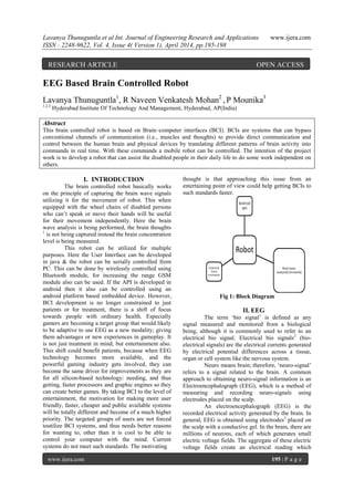
- 1. Lavanya Thunuguntla et al Int. Journal of Engineering Research and Applications www.ijera.com ISSN : 2248-9622, Vol. 4, Issue 4( Version 1), April 2014, pp.195-198 www.ijera.com 195 | P a g e EEG Based Brain Controlled Robot Lavanya Thunuguntla1 , R Naveen Venkatesh Mohan2 , P Mounika3 1,2,3 Hyderabad Institute Of Technology And Management, Hyderabad, AP(India) Abstract This brain controlled robot is based on Brain–computer interfaces (BCI). BCIs are systems that can bypass conventional channels of communication (i.e., muscles and thoughts) to provide direct communication and control between the human brain and physical devices by translating different patterns of brain activity into commands in real time. With these commands a mobile robot can be controlled. The intention of the project work is to develop a robot that can assist the disabled people in their daily life to do some work independent on others. I. INTRODUCTION The brain controlled robot basically works on the principle of capturing the brain wave signals utilizing it for the movement of robot. This when equipped with the wheel chairs of disabled persons who can’t speak or move their hands will be useful for their movement independently. Here the brain wave analysis is being performed, the brain thoughts 1 is not being captured instead the brain concentration level is being measured. This robot can be utilized for multiple purposes. Here the User Interface can be developed in java & the robot can be serially controlled from PC. This can be done by wirelessly controlled using Bluetooth module, for increasing the range GSM module also can be used. If the API is developed in android then it also can be controlled using an android platform based embedded device. However, BCI development is no longer constrained to just patients or for treatment, there is a shift of focus towards people with ordinary health. Especially gamers are becoming a target group that would likely to be adaptive to use EEG as a new modality; giving them advantages or new experiences in gameplay. It is not just treatment in mind, but entertainment also. This shift could benefit patients, because when EEG technology becomes more available, and the powerful gaming industry gets involved, they can become the same driver for improvements as they are for all silicon-based technology: needing, and thus getting, faster processors and graphic engines so they can create better games. By taking BCI to the level of entertainment, the motivation for making more user friendly, faster, cheaper and public available systems will be totally different and become of a much higher priority. The targeted groups of users are not forced toutilize BCI systems, and thus needs better reasons for wanting to, other than it is cool to be able to control your computer with the mind. Current systems do not meet such standards. The motivating thought is that approaching this issue from an entertaining point of view could help getting BCIs to such standards faster. Fig 1: Block Diagram II. EEG The term ‘bio signal’ is defined as any signal measured and monitored from a biological being, although it is commonly used to refer to an electrical bio signal. Electrical bio signals2 (bio- electrical signals) are the electrical currents generated by electrical potential differences across a tissue, organ or cell system like the nervous system. Neuro means brain; therefore, ‘neuro-signal’ refers to a signal related to the brain. A common approach to obtaining neuro-signal information is an Electroencephalograph (EEG), which is a method of measuring and recording neuro-signals using electrodes placed on the scalp. An electroencephalograph (EEG) is the recorded electrical activity generated by the brain. In general, EEG is obtained using electrodes3 placed on the scalp with a conductive gel. In the brain, there are millions of neurons, each of which generates small electric voltage fields. The aggregate of these electric voltage fields create an electrical reading which RESEARCH ARTICLE OPEN ACCESS
- 2. Lavanya Thunuguntla et al Int. Journal of Engineering Research and Applications www.ijera.com ISSN : 2248-9622, Vol. 4, Issue 4( Version 1), April 2014, pp.195-198 www.ijera.com 196 | P a g e electrodes on the scalp are able detect and record. Therefore, EEG is the superposition of many simpler signals. The amplitude of an EEG signal typically ranges from about 1 µV to 100 µV in a normal adult, and it is approximately 10 to 20 mV when measured with subdural electrodes such as needle electrodes. 2.1 EEG analysis The FFT (Fast Fourier Transform) is a mathematical process which is used in EEG analysis to investigate the composition of an EEG signal. Since the FFT transforms a signal from the time domain into the frequency domain, frequency distributions of the EEG can be observed. EEG frequency distribution is very sensitive to mental and emotional states as well as to the location of the electrode(s).Two types of EEG montages are used: monopolar and bipolar. The monopolar montage collects signals at the active site and compares them with a common reference electrode. The common electrode should be in a location so that it would not be affected by cerebral activity. The main advantage of the monopolar montage is that the common reference allows valid comparisons of the signals in many different electrode pairings. Disadvantages of the monopolar montage include that there is no ideal reference site, although the earlobes are commonly used. In addition, EMG and ECG artifacts4 may occur in the monopolar montage. Bipolar montage compares signals between two active scalp sites.Any activity in common with these sites is subtracted so that only difference in activity is recorded.Therefore some information is lost with this montage. The 10-20 international system is used as the standard naming and positioning scheme for EEG measurements. The original 10-20 system included only 19 electrodes. Later on, extensions were made so that 70 electrodes could be placed in standard positions. Generally one of the electrodes is used as the reference position, often at the earlobe or mastoid location. The brain have always fascinated humans. New methods for exploring it have been found and we can categorize them into two main groups. Invasive and non-invasive. An invasive approach requires physical implants of electrodes in humans or animals, making it possible to measure single neurons or very local field potentials. A non-invasive approach makes use of, for instance, magnetic resonance imaging (MRI) and EEG technology to make measurements. Both gives different perspectives and enables us to look inside the brain and to observe what happens. Fig 2: Original 10-20 System EEG is generally described in terms of its frequency band. The amplitude of the EEG shows a great deal of variability depending on external stimulation as well as internal mental states. Delta, theta ,alpha, beta and gamma are the names of the different EEG frequency bands. NeuroSky has developed a dry sensor system for consumer applications of EEG technology. NeuroSky5 system consists of dry electrodes and a specially designed electronic circuit for the dry electrodes. NeuroSky has been conducting benchmark tests of the dry EEG by comparing EEG signals measured by the dry sensor system with signals from the Biopac system, a well known wet electrode EEG system widely used in medical and research applications. EEG was simultaneously recorded by the NeuroSky system and the Biopac system. Electrodes for the two systems were placed at the same location, as close together as possible without interfering with one another. Gold-plated dry electrodes were used for NeuroSky system, while silver-silver-chloride disposable electrodes with gel were used for Biopac system. Brain Wave type Frequency range Mental states & Conditions Delta 0.1Hz-3 Hz Deep, dreamless sleep, non-REM sleep, unconscious Theta 4 Hz-7 Hz Intuitive, creative, recall, fantasy, imaginary, dream Alpha 8 Hz-12 Hz Relaxed, but not drowsy, tranquil, conscious
- 3. Lavanya Thunuguntla et al Int. Journal of Engineering Research and Applications www.ijera.com ISSN : 2248-9622, Vol. 4, Issue 4( Version 1), April 2014, pp.195-198 www.ijera.com 197 | P a g e Low beta 12 Hz-15 Hz Formerly SMR, relaxed yet focused, integrated Mid range beta 16 Hz-20 Hz Thinking, aware of self & surroundings High beta 21 Hz-30 Hz Alertness, agitation Gamma 30 Hz-100 Hz Motor Functions, higher mental activity Fig 3 : Different Brain states at different frequecies 2.2 EEG Artifacts Since EEG signals are very weak (ranging from 1 to 100 µV), they can easily be contaminated by other sources. An EEG signal that does not originate from the brain is called an artifact. Artifacts can be divided into two categories: physiologic and non-physiologic. Any source in the body which has an electrical dipole or generates an electrical field is capable of producing physiologic artifacts. These include the heart, eyes, muscle, and tongue. Sweating can also alter the impedance at the electrodescalp interface and produce an artifact. Non-physiologic artifacts include 60 Hz interference from electric equipment, kinesiologic artifacts caused by body or electrode movements, and mechanical artifacts caused by body movement. III. Results and Discussion Brain-computer interface is a method of communication based on neural activity generated by the brain and is independent of its normal output pathways of peripheral nerves and muscles. The goal of BCI is not to determine a person’s intent by eavesdropping on brain activity, but rather to provide a new channel of output for the brain that requires voluntary adaptive control by the user. The Fourier Transformation and extraction of band powers is by far the most applied method for signal processing and analysis The algorithm is based on discrete Fourier transform (DFT) and by applying that to the EEG signal it makes it possible to separate the EEG rhythms. Definition: N-1 Xk=∑ xne-(i2kπn)/N k=0,….N-1. n=0 The performance of the DTF is O(N2 ), but there is a more efficient algorithm called fast Fourier Transform (FFT), that can compute the same result in only O(NlogN). This is a great improvement and one of the reasons why FFT is the favorable method of analyzing EEG signals, and other waves like sound. The Problems faced with BCI design are Noise-They have poor signal-to-noise ratio, The EEG signals vary rapidly (Non-Stationary). The process flow BCI can be shown in the below block diagram Fig 4 : Flow of BCI BCI robot can be used in Bioengineering applications: Devices with assisting purposes for disabledpeople , Human subject monitoring: Research and detection of sleep disorders, neurological diseases, attention monitoring, and/or overall ”mental state” ,. Neuroscience research: real- time methods for correlating observable behavior with recorded neural signals, Human-Machine Interaction: Interface devices between humans, computers or machines. IV. CONCLUSION Here a single robot is used for multiple purposes thereby reducing cost for designing multiple robots. It gives a optimized as well as customized solution of general robots which we require. REFERENCES [1] Lopes da Silva, F., Functional localization of brain sources using EEG and/or MEG data: volume conductor and source models. Magn Reson Imaging, 2004. 22(10): p. 1533-8. [2] Delorme, A. and S. Makeig, EEGLAB: an open source toolbox for analysis of single-trial EEG dynamics including independent component analysis. J Neurosci Methods, 2004. 134(1): p. 9-21. [3] Benjamini, Y. and Y. Hochberg, Controlling the false discovery rate: a practical and powerful approach to multiple testing. Journal of the Royal Statistical Society, Series B (Methodological), 1995. 57(1): p. 289-300. [4] McKinnon, K.I.M., Convergence of the Nelder-Mead simplex method to a non- stationary point. SIAM J Optimization, 1999. 9: p. 148-158. [5] Andrew T Campbell, Tanzeem Choudhury, Shaohan Hu, Hong Lu, Mashfiqui Rabbi, Rajeev D S Raizada, M. K. M. . (2010). NeuroPhone:Brain-MobilePhone Interface using a Wireless EEG Headset. MobiHeld 2, 3–8.
- 4. Lavanya Thunuguntla et al Int. Journal of Engineering Research and Applications www.ijera.com ISSN : 2248-9622, Vol. 4, Issue 4( Version 1), April 2014, pp.195-198 www.ijera.com 198 | P a g e Author (s) Author 1: Ms Lavanya Thunuguntla has 8 years of Teaching experience and presently working as an Associate Professor in the Department of ECE in Hyderabad Institute of Technology and Management (HITAM), Hyderabad, AP(India). She received her B.Sc degree in Computer Science from Acharya Nagarjuna University in 2002, M.Sc degree in Physics from University of Hyderabad, Hyderabad in 2004 and M.Tech from Indian Institute of Technology (IIT) Kharagpur in 2007. She has Professional Membership in IEEE,WIE. She has various National & International journal publications. She has guided several M.Tech and B.Tech projects. She has strong motivation towards research in the fields of Nano Technology, Microwave and Optical & Analog Communications ,VLSI system design etc. She can be reached at lavanya_iitkgp@yahoo.co.in Author 2 G Naveen Venkatesh Mohan is pursuing Fourth Year B.Tech in Electronics & Communication Engineering branch in Hyderabad Institute of Technology and Management (HITAM), Hyderabad, AP(India). He gave presentations in various National level contests.His areas of interests are Communications,VLSI system Design etc. Author 3 P Mounika is pursuing Fourth Year B.Tech in Electronics & Communication Engineering branch in Hyderabad Institute of Technology and Management (HITAM), Hyderabad, AP(India). She gave presentations in various National level contests.Her areas of interests are Nanotechnology ,VLSI system Design etc.