Design and power transmission of advanced light helicopters

The document discusses the design and power transmission system of an advanced light helicopter. It describes the four main gearboxes - the main gearbox, auxiliary gearbox, intermediate gearbox, and tail gearbox. The main gearbox increases torque and reduces speed from the engine before transmitting power to the other gearboxes. The auxiliary gearbox cools the main gearbox oil before transmitting power to the intermediate gearbox. The intermediate gearbox redirects the driveline upward at a 125 degree angle to the tail gearbox. The tail gearbox then drives the tail rotor blades to provide counteracting thrust. Shims are used between gears in the gearboxes to achieve the proper gear mesh patterns and backlash during assembly given manufacturing variations in part

Recommandé
Recommandé
Contenu connexe
Tendances
Tendances (20)
En vedette
En vedette (7)
Similaire à Design and power transmission of advanced light helicopters
Similaire à Design and power transmission of advanced light helicopters (20)
Dernier
Dernier (20)
Design and power transmission of advanced light helicopters
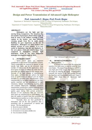
- 1. Prof. Amarnath.V. Hegne, Prof. Preeti. Hegne / International Journal of Engineering Research and Applications (IJERA) ISSN: 2248-9622 www.ijera.com Vol. 3, Issue 4, Jul-Aug 2013, pp.219-223 219 | P a g e Design and Power Transmission of Advanced Light Helicopter Prof. Amarnath.V. Hegne, Prof. Preeti. Hegne Department of Mechanical Engineering, SVERI’S College Of Engineering, Pandharpur, Dist:Solapur, Maharashtra,India Department of Computer Science Engineering, SVERI’S College Of Engineering, Pandharpur, Dist:Solapur, Maharashtra,India ABSTRACT Helicopters are the light and fast moving flying transporters. The situations like less number of passengers, flood relief; supply of food & water to the soldiers working in hilly regions in the border, war time attacking rescuing people from fire in multi stored Building etc gave importance to the use of helicopters. Helicopters are more useful to the defense services of every country. It is very useful in limitations that are not conducive to the aero planes which are relative large when compared to helicopters. Advance light helicopter( ALH) is one such indigenous helicopter developed in India by HAL. I. INTRODUCTION Spiral bevel gears are important components on all current rotorcraft drive systems. These components are required to operate at high speeds, high loads, and for an extremely large number of load cycles. In this application, spiral bevel gears are used to redirect the shaft from the horizontal gas turbine engine to the vertical rotor. Because of the high expense of manufacturing these gears, methods that can achieve the same level of performance at reduced cost are highly desirable to aerospace gear manufacturers. Gears manufactured for aerospace applications use high- quality materials and are manufactured to tight tolerances. Special manufacturing machine tools and computer numerically controlled coordinate measurement systems have enabled rotorcraft drive system manufacturers to produce extremely high- quality gears during their normal production. Because of low production rates for rotorcraft, these gears are manufactured in small batches, and thus are unable to benefit from the economics of high production numbers as in other industries. Normally there are four gearboxes in helicopters and all the four gearboxes play a prominent role in transmission of motion and power. The four gearboxes are MAIN GEARBOX (MGB) AUXILIARY GEARBOX (AGB) INTERMEDIATE GEARBOX (IGB) AND TAIL GEARBOX (TGB) Fig1: Advanced Light Helicopter II. DESIGN & WORKING Main gearbox: It receives the motion from the engine and transfers it to main rotor, in order to rotate the main rotor blades. The output from the engine in RPM is very high and of low torque, thus MGB increases the torque by reducing the speed. Simultaneously transmits the motion to the Tail gearbox through the Auxiliary and Intermediate gearboxes. Figure 2 shows Main Gear Box of Advanced light helicopter. Figure 2: Main Gear Box of Advanced light helicopter
- 2. Prof. Amarnath.V. Hegne, Prof. Preeti. Hegne / International Journal of Engineering Research and Applications (IJERA) ISSN: 2248-9622 www.ijera.com Vol. 3, Issue 4, Jul-Aug 2013, pp.219-223 220 | P a g e Auxiliary Gearbox: The lubricating oil in the MGB gets heated to a temperature of around 100o , in order to reduce the temperature of oil, so that the lubricating capacity of the oil is in tact, AGB is provided which is used to cool the MGB oil and re-circulate the cooled oil to the MGB. It is also used to drive various auxiliary equipments and to transmit power to IGB. Tail drive shafts are used to transmit the motion from Auxiliary gearbox to Tail gearbox through Intermediate gearbox. Sliding spline connection is provided between the IGB and the TGB (i.e. Shaft between the IGB and TGB). This accommodates mounting tolerances and differential thermal expansion of tail rotor drive shaft and tail boom structure. Figure 3 shows Auxiliary Gear Box of Advanced Light Helicopter. Figure 3: Auxiliary Gear Box of Advanced Light Helicopter Intermediate Gearbox: Intermediate gearbox is mounted on the tail boom at its intersection with the canted vertical fin. It has one stage of spiral bevel gearing which serves to redirect the driveline upward to the tail gearbox through a 125° angle. It also provides a small speed reduction (i.e. the speed reduction ratio is 4163/4033). The estimated dry weight of the IGB assembly is 15 kg. Figure 4 shows Auxiliary Gear Box of Advanced Light Helicopter. Figure 4: Auxiliary Gear Box of Advanced Light Helicopter Tail Gearbox: The main purpose of the Tail gearbox is to drive the tail rotor blade by receiving the power from the IGB by means of a tail drive shaft. The basic purpose of the tail rotor blade is to give a force in a direction opposite to the force generated by the main gear box by virtue of friction which tries to rotate the whole of the helicopter with it , such that the whole of the helicopter is in a stable position during the course of the flight. Figure 2 shows different locations of all gear boxes in ALH. Figure 5 shows Tail Gear Box of Advanced Light Helicopter. Figure 5: Tail Gear Box of Advanced Light Helicopter
- 3. Prof. Amarnath.V. Hegne, Prof. Preeti. Hegne / International Journal of Engineering Research and Applications (IJERA) ISSN: 2248-9622 www.ijera.com Vol. 3, Issue 4, Jul-Aug 2013, pp.219-223 221 | P a g e III. ASSEMBLY & PATTERN PROCEDURE When to gears are made to mesh and rotated the area in which they have their area being contacted is called a pattern which can be visualized by painting the tooth surface area by a paint before they are made to mesh and the same can be transferred onto a cello tape and then onto a paper for further reference . The load shared between the teeth is directly proportional to the area of contact. The gear boxes when assembled should confirm to a standard static pattern so that they have satisfactory performance when running on the helicopter, but because of the variations occurring in the production of the parts, obtaining a standard static pattern directly with the given parts is not possible and as such shims are used to vary the distances between the gears within the gear box to obtain the standard pattern during assembly. After obtaining the pattern it is made to agree with the pattern obtained on a precision machine confirming to the actual mounting distance , incase it is not shim sizes are varied and the pattern is adjusted such that it is obtained as per the pattern obtained on the machine. Figure 6 shows different locations of all gear boxes in Advanced Light Helicopter. Objectives of present Study: No two parts can be produced to similar dimensions, due to change in machine, operator, machining environment etc... The same applies to the Housings and the Gears used in the gearboxes. In order to compensate for the deviations in any of the dimensions of the Housing center distance and gear mounting distances Shims are used. It is a must to obtain the required pattern and backlash before actually the gearbox is fit on to the helicopter. Figure 7 shows Teeth & RPM. The objectives of the present study are To calculate the Exact Thickness of the Shim needed to have a perfect pattern. To reduce the number of iterations required to obtain the adequate backlash and pattern. To reduce the Time of assembly. Figure 6: Different locations of all gear boxes in Advanced Light Helicopter IV. GEAR PARAMETERS, GEAR MESHING, TEETH & RPM N0 Particulars Units Input Collector Tail power tap off 1 No of teeth 27/79 17/111 17/111 2 Driving Member Pinion Pinion Gear 3 Pinion speed RPM 6000 2050.63 2050.63 4 Gear Speed RPM 2050.63 314.06 314.06 Design Power 280 KW Table 1: Gear parameters
- 4. Prof. Amarnath.V. Hegne, Prof. Preeti. Hegne / International Journal of Engineering Research and Applications (IJERA) ISSN: 2248-9622 www.ijera.com Vol. 3, Issue 4, Jul-Aug 2013, pp.219-223 222 | P a g e Figure 7: TEETH & RPM V. CONCLUSION Advaced Light Helicopters can be used for Ambulance Role, Civil Purpose, Skid Variant, Wheeled Variant, Disaster Relief Operation, Offshore Operations, Armed Role, Coast Guard Role, High Altitude Operations, Maritime Operations, Policing Duties Sarang Display Team of IAF. Gear box diagnosis technique based on cepstrum analysis. The performances of this technique in the gear system diagnosis have been compared to those of the synchronous cepstre method and the expertise report. The application of this technique to the vibration signal emitted by the gear reductor system permits to conclude that it can play an important role in the study of gear vibrations. In fact, the use state of a reductor is strongly related to modulation phenomena that present the vibrations relative to the meshing signal. We have shown that by Time signal and Cepstrum energy of the vibration signal averaged according the LCM of the first gear we can detect the fault which is misalignment of drive shaft in gearbox of helicopter. REFERENCES [1] Leila.nacib , Komi Midzodzi, “Detecting Shaft Misallignment in Gearbox of Helicopter Using Average Synchronous Analysis” ,International Journal of Engineering & Technology IJET-IJENS Vol:12 No:06. [2] K.M. Pandey, A. Surana and D. Deka,“ Numerical analysis of helicopter rotor at 400 rpm” , International Journal of Soft Computing and [3] Engineering (IJSCE) ISSN: 2231-2307, Volume-2, Issue-1, March 2012. [4] Pieter Abbeel, Adam Coates and Andrew Y, “Autonomous Helicopter Aerobatics through Apprenticeship Learning” The International Journal of Robotics Research OnlineFirst, published on June 23, 2010 as doi:10.1177/0278364910371999. [5] Rakesh Kumar Kumawat, “Analysis for an Efficient Wireless Power Transmission” international journal of scientific & engineering research, volume 3, issue 9, september-2012 1 issn 2229-5518. [6] Gavrilets, E. Frazzoli, B. Mettler, M. Piedmonte and E. Feron “Aggressive Maneuvering of Small Autonomous Helicopters: A Human-Centered Approach”The International Journal of Robotics Research 2001; 20; 795 DOI: 10.1177/02783640122068100 [7] M. zacksenhouse, s. Braun and m Feldman “Toward helicopter gearbox diagnostics from a small number of examples” mechanical systems and signal processing (2000) doi:10.1006/mssp.2000.1297. [8] C. K. Zioutis, A. I. Spyropoulos, A. P. Fragias, D. P. Margaris & D. G. Papanikas, “Influence of Helicopter Rotor Wake Modeling on Blade Airload Predictions” International Journal of Engineering (IJE), Volume (3): Issue (6) 521. [9] Zhenyu Yu, Kenzo Nonami, Jinok Shin and Demian Celestino “3D Vision Based
- 5. Prof. Amarnath.V. Hegne, Prof. Preeti. Hegne / International Journal of Engineering Research and Applications (IJERA) ISSN: 2248-9622 www.ijera.com Vol. 3, Issue 4, Jul-Aug 2013, pp.219-223 223 | P a g e Landing Control of a Small Scale Autonomous Helicopter” International Journal of Advanced Robotic Systems, Vol. 4, No. 1 (2007) ISSN 1729‐8806, pp. 51–56. [10] S. Sheik Mohammed , K. Ramasamy , T. Shanmuganantham ,“Wireless Power Transmission – A Next Generation Power Transmission System” ©2010 International Journal of Computer Applications (0975 – 8887) Volume 1 – No. 13 [11] www.hal-india.com