D42061620
•
0 j'aime•490 vues

This document describes a system to help prevent fishermen from crossing maritime boundaries and entering dangerous areas. It uses GPS, ultrasonic sensors, a vibration sensor and microcontroller on boats. The GPS tracks the boat's position and the microcontroller compares it to boundary coordinates. If the boat approaches or crosses the boundary, an alarm alerts the fishermen. It also sends a message to coastal guards. Ultrasonic sensors detect icebergs and the vibration sensor predicts tsunamis. If the boat keeps moving past the boundary, the motor can be remotely stopped. The system aims to save lives by keeping fishermen from entering restricted or dangerous waters.
![Miss.Lavanya.G et al Int. Journal of Engineering Research and Applications
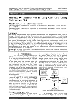
ISSN : 2248-9622, Vol. 4, Issue 2( Version 6), February 2014, pp.16-20
from the satellite, this processes is carried out by the
known values and details of the longitude and
latitude of the various countries which is extracted
from the GPS system and passed on to the
microcontroller.
The
microcontroller
calculates
the
longitude’s and latitude’s value along with the stored
boundary position and indicates the navigators
through an alarm that the vehicle is in danger. This
microcontroller system is also connected to the base
station, so once alarm in the ship/boat is one a
message from the microcontroller is sent to the base
station which is done through the message
transmitter. As soon as the message is passed to the
coastal guards the navigator is rescued. Thus through
this system an indication is passed to both the coastal
guards and the fisherman which reduces the risks of
many lives who sail in the sea.
II. ROLE OF GPS
Global Positioning System is sends and
receives radio signals and it is a satellite based
navigation system. A GPS receiver acquires these
signals and provides with information. GPS location
determines location, velocity and time 24 hours a day
in any weather conditions anywhere in the world for
free. Global Positioning System, originally was
developed for the military and maritime because of
its popular navigation capabilities and can access
GPS
technology
using
small
inexpensive
equipment.[3]
Segment Spacing
At least 24 GPS satellites orbit the earth
twice a day in a specific pattern. They travel at
approximately 7000 miles per hour about 12000
miles above the earth’s surface. These satellites are
spaced so that a GPS receiver anywhere in the world
can receive signals from at least four of them. Each
GPS satellite constantly sends coded radio signals
(known as pseudorandom code) to the earth. These
GPS satellite signals contain the following
information like the particular satellite that is sending
the information, where that satellite should be at the
given time, whether the satellite is working properly.
The date and time the satellite sent the signal etc. The
signals can pass through cloud, glass and plastic.
Most solid objects such as buildings attenuate the
signals. The signals cannot pass through objects that
contain a lot of metal or objects that contain water.
The GPS satellites are powered by solar energy. If
solar energy is unavailable then the satellite uses
backup batteries to continue running. Each GPS
satellite is built to last about 10 years.
www.ijera.com
www.ijera.com
Segment Controlling
The segment controlling is responsible for
monitoring the signal integrity, satellite health and
orbit configuration. It also includes master control on
ground antennas, control station and monitor station
At least six unmanned monitor stations are located
around the world. The master control station (MCS)
constantly monitors and receives information from
the GPS satellites and then sends the clock and
orbital information to each station. The controllers in
the MCS make precise corrections to the data and
send the information to the GPS satellites through the
ground antennas.
Ground Antennas
Ground Antennas sends the corrected
information to the satellite by receiving the decrypted
orbital clock information from the MCS. Since all of
the satellite signals are modulated onto the same
carrier frequency, there is a need to separate the
signals after demodulation.
GPS User Segment
The GPS user segment consists of the GPS
receiver which determines and displays the speed
time and location by collecting and processing the
signals from the GPS satellites that are viewed. GPS
receiver only receivers information but does not
transmit any information back to the satellites. The
satellite signals are modulated by the carrier
frequency, so there is a need to separate the signals
after demodulation. This process is done by assigning
each satellite a gold coin which is a unique binary
sequence and the signals are then decoded after
demodulation using modulo 2 additions of the gold
codes corresponding to the satellites nk, where k is
the number of channels in the GPS receiver and n k
are the PRN identifiers of the satellites. The PRN
identifier ranges from 1 to 32 which is given to each
satellites and they are unique identifiers. The results
of each modulo 2 additions from the satellites ni
through nk are 50 bit/s navigation message. The gold
codes used in GPS are a sequence of 1023 bits with a
period of one millisecond [2]. These satellite signals
are unlike with each other such that the gold codes
are highly mutually orthogonal, so that one satellite
signal will be misinterpreted as another. These gold
codes are applicable due to its good auto-correlation
properties.
III. WIRELESS SENSOR NETWORK
ZigBee technology is a low power
consumption, low data rate, low cost, wireless
networking protocol targeted towards
remote
control and automation applications. ZigBee provides
low power and low cost connectivity for equipment
which needs a long battery life as long as several
17 | P a g e](data:image/gif;base64,R0lGODlhAQABAIAAAAAAAP///yH5BAEAAAAALAAAAAABAAEAAAIBRAA7)
Recommandé
Recommandé
Contenu connexe
En vedette
Similaire à D42061620
Similaire à D42061620 (20)
Dernier
Dernier (20)
D42061620
- 1. Miss.Lavanya.G et al Int. Journal of Engineering Research and Applications ISSN : 2248-9622, Vol. 4, Issue 2( Version 6), February 2014, pp.16-20 RESEARCH ARTICLE www.ijera.com OPEN ACCESS Modeling Of Maritime Vehicle Using Gold Coin Coding Technique and GPS Miss.Lavanya.G1, Ms. Sneha Susan Abraham2 1 (Assistant Professor, Department of Electronics and Communication Engineering, Saveetha University, Chennai-602105) 2 (Assistant Professor, Department of Electronics and Communication Engineering, Saveetha University, Chennai-602105) ABSTRACT The main aim of the project is to identify the ship or boat on the zone level. While travelling in boat or ship the iceberg in the sea is detected by using ultrasonic sensor and the prediction of tsunami is carried out using vibration sensor. If the boat or ship crosses the limitation of border it gives a voice message, if they try to move forward then the ship/boat will automatically stop functioning. There is one emergency switch available on the boat side that will inform about the route to home. In the problematic time, the information is passed to the control room then the ship/boat is rescued in case of danger. A GPS receiver shows the position of the ship/boat by receiving the signal from the satellite. The microcontroller is used to calculate the accurate position of the boat/ship which will indicate the fisherman through an alarm system that the ship/boat has crossed the boundary. Through this process the system helps in saving the lives of the fisherman and reduces the risks and damages caused to them when they are lost in the sea. Keywords - The master control station (MCS), Global Positioning System (GPS), Universal Asynchronous Receiver/Transmitter (UART) I. INTRODUCTION This paper deals with the usefulness of a GPS device in maritime vehicles. The main objective of the paper is to avoid navigation of the fishermen beyond the border of other countries. As per the day to day issues once the fishermen crosses the maritime boundaries they are shot dead, taking this into consideration this paper deals with a GPS (Global Positioning System) and a microcontroller is fixed along with the maritime vehicles which helps on saving the lives of the fisherman. The GPS system provides the reliable position of the vehicles to the worldwide users in all weather conditions, anywhere near or on the earth or during the day or night time in a continuous basis. GPS is composed of three segments: user, control and space. As the maritime boundary of a country cannot be marked, none of the current GPS system has satisfied the requirements for the safety of civilian navigation in the sea. In this paper, an alert alarm is given to the fishermen when the ship/boat nears or crosses the boundary. In addition to the alarm, a message is transmitted to the base station along the shores stating that the maritime vehicle has crossed the boundary. Existing system and proposed system Electronic map and the GPS system are used in boats/ships to identify the accurate position, which www.ijera.com is the existing system. By using this system there is an increased level of safety for the mariners worldwide. The electronic map not only finds its accurate position but also ensures that the vessel reaches its destination safely. The difficulty in finding the position has become more critical as the boat/ship departs the country is detected between India and Sri Lanka. The problem occurs mainly when the fisherman crosses the maritime border of the neighboring country, as they are not aware of the limits and boundaries in sea. WIRELESS SENSOR NETWOR KS GPS LCD VOICE BOARD MICRO CONTROLL ER ULTR A SONIC SENSO R DC MOTOR Figure 1 Proposed system block diagram As in the figure 1 the GPS receiver shows the position of the ship/boat by receiving the signal 16 | P a g e
- 2. Miss.Lavanya.G et al Int. Journal of Engineering Research and Applications ISSN : 2248-9622, Vol. 4, Issue 2( Version 6), February 2014, pp.16-20 from the satellite, this processes is carried out by the known values and details of the longitude and latitude of the various countries which is extracted from the GPS system and passed on to the microcontroller. The microcontroller calculates the longitude’s and latitude’s value along with the stored boundary position and indicates the navigators through an alarm that the vehicle is in danger. This microcontroller system is also connected to the base station, so once alarm in the ship/boat is one a message from the microcontroller is sent to the base station which is done through the message transmitter. As soon as the message is passed to the coastal guards the navigator is rescued. Thus through this system an indication is passed to both the coastal guards and the fisherman which reduces the risks of many lives who sail in the sea. II. ROLE OF GPS Global Positioning System is sends and receives radio signals and it is a satellite based navigation system. A GPS receiver acquires these signals and provides with information. GPS location determines location, velocity and time 24 hours a day in any weather conditions anywhere in the world for free. Global Positioning System, originally was developed for the military and maritime because of its popular navigation capabilities and can access GPS technology using small inexpensive equipment.[3] Segment Spacing At least 24 GPS satellites orbit the earth twice a day in a specific pattern. They travel at approximately 7000 miles per hour about 12000 miles above the earth’s surface. These satellites are spaced so that a GPS receiver anywhere in the world can receive signals from at least four of them. Each GPS satellite constantly sends coded radio signals (known as pseudorandom code) to the earth. These GPS satellite signals contain the following information like the particular satellite that is sending the information, where that satellite should be at the given time, whether the satellite is working properly. The date and time the satellite sent the signal etc. The signals can pass through cloud, glass and plastic. Most solid objects such as buildings attenuate the signals. The signals cannot pass through objects that contain a lot of metal or objects that contain water. The GPS satellites are powered by solar energy. If solar energy is unavailable then the satellite uses backup batteries to continue running. Each GPS satellite is built to last about 10 years. www.ijera.com www.ijera.com Segment Controlling The segment controlling is responsible for monitoring the signal integrity, satellite health and orbit configuration. It also includes master control on ground antennas, control station and monitor station At least six unmanned monitor stations are located around the world. The master control station (MCS) constantly monitors and receives information from the GPS satellites and then sends the clock and orbital information to each station. The controllers in the MCS make precise corrections to the data and send the information to the GPS satellites through the ground antennas. Ground Antennas Ground Antennas sends the corrected information to the satellite by receiving the decrypted orbital clock information from the MCS. Since all of the satellite signals are modulated onto the same carrier frequency, there is a need to separate the signals after demodulation. GPS User Segment The GPS user segment consists of the GPS receiver which determines and displays the speed time and location by collecting and processing the signals from the GPS satellites that are viewed. GPS receiver only receivers information but does not transmit any information back to the satellites. The satellite signals are modulated by the carrier frequency, so there is a need to separate the signals after demodulation. This process is done by assigning each satellite a gold coin which is a unique binary sequence and the signals are then decoded after demodulation using modulo 2 additions of the gold codes corresponding to the satellites nk, where k is the number of channels in the GPS receiver and n k are the PRN identifiers of the satellites. The PRN identifier ranges from 1 to 32 which is given to each satellites and they are unique identifiers. The results of each modulo 2 additions from the satellites ni through nk are 50 bit/s navigation message. The gold codes used in GPS are a sequence of 1023 bits with a period of one millisecond [2]. These satellite signals are unlike with each other such that the gold codes are highly mutually orthogonal, so that one satellite signal will be misinterpreted as another. These gold codes are applicable due to its good auto-correlation properties. III. WIRELESS SENSOR NETWORK ZigBee technology is a low power consumption, low data rate, low cost, wireless networking protocol targeted towards remote control and automation applications. ZigBee provides low power and low cost connectivity for equipment which needs a long battery life as long as several 17 | P a g e
- 3. Miss.Lavanya.G et al Int. Journal of Engineering Research and Applications ISSN : 2248-9622, Vol. 4, Issue 2( Version 6), February 2014, pp.16-20 months to years but does not require data transfer rates as high as those enabled by Bluetooth. In addition, ZigBee can also be implemented using mesh networks. ZigBee compliant wireless devices are expected to transmit 10-75 meters, depending on the RF environment and the power output consumption required for a given application, and will operate in the RF. The data rate is 250kbps at 2.4GHz, 40kbps at 915MHz and 20kbps at 868MHz. ZigBee looks rather like Bluetooth but is simpler, has a lower data rate and spends most of its time snoozing. ZigBee uses a basic master-slave configuration suited to static star networks of many infrequently used devices that talk via small data packets. It allows up to 254 nodes. This characteristic means that a node on a ZigBee network should be able to run for six months to two years on just two AA batteries. The operational range of ZigBee is 1075m compared to 10m for Bluetooth. Bluetooth’s protocol is more complex since it is geared towards handling voice, images and file transfers in ad hoc networks. Bluetooth devices can support scatter nets of multiple smaller non-synchronized networks (piconets). It only allows up to 8 slave nodes in a basic master-slave piconet set-up. When ZigBee node is powered down, it can wake up and get a packet in around 15 msec whereas a Bluetooth device would take around 3sec to wake up and respond. In this paper we use ultrasonic sensor, vibration sensor and home switch as the inputs to the microcontroller. Ultrasonic sensors (also known as transceivers when they both send and receive) work on a principle similar to radar or sonar which evaluate attributes of a target by interpreting the echoes from radio or sound waves respectively. Ultrasonic sensors generate high frequency sound waves and evaluate the echo which is received back by the sensor. Sensors calculate the time interval between sending the signal and receiving the echo to determine the distance to an object. This technology can be used for measuring wind speed and direction (anemometer), fullness of a tank and speed through air or water. For measuring speed or direction a device uses multiple detectors and calculates the speed from the relative distances. To measure the amount of liquid in a tank, the sensor measures the distance to the surface of the fluid. Systems typically use a transducer which generates sound waves in the ultrasonic range, above 18,000 hertz, by turning electrical energy into sound, then upon receiving the echo turn the sound waves into electrical energy which can be measured and displayed. Ultrasonic Transducers An ultrasonic transducer is a device that converts energy into ultrasound, or sound waves www.ijera.com www.ijera.com above the normal range of human hearing. Piezoelectric crystals have the property of changing size when a voltage is applied, thus applying an alternating current (AC) across them causes them to oscillate at very high frequencies, thus producing very high frequency sound waves. Since piezoelectric crystals generate a voltage when force is applied to them, the same crystal can be used as an ultrasonic detector. The output of the ultrasonic sensor is then given to the microcontroller. Similarly even the output of the vibration sensor and home switch is given to the microcontroller. The vibration switch is used for the prediction of tsunami i.e piezoelectric sensor is a device that uses the piezoelectric effect to measure pressure, acceleration, strain or force by converting them to an electrical signal. The microcontroller then processes and displays it on the LCD indicating that the vessel has crossed the border, it even gives an alert with the help of voice board in which nearly 8 different voice messages can be stored. If the vessel still continues to cross the border and move forward then with the help of relay switch the dc-motor of the ship can be turned off. Once the motor is off then the message is sent to the coastal guard with the help of wireless sensor network. UART A UART is used for the serial communication of the data. The indication of the crossing of the border by the vessel is given to both the fishermen and to the coastal guard. The Universal Asynchronous Receiver/Transmitter (UART) controller is the key component of the serial communications. The UART takes bytes of data and transmits the individual bits in a sequential fashion. At the destination, a second UART re-assembles the bits into complete bytes. Serial transmission of digital information (bits) through a single wire or other medium is much more cost effective than parallel transmission through multiple wires. It is used to convert the transmitted information between its sequential and parallel form at each end of the link. Each UART contains a shift register which is the fundamental method of conversion between serial and parallel forms. A relay is an electrically operated switch. Current flowing through the coil of the relay creates a magnetic field which attracts a lever and changes the switch contacts. The coil current can be on or off so relays have two switch positions and they are double throw (changeover) switches. Relays allow one circuit to switch a second circuit which can be completely separate from the first. Relays are usually SPDT or DPDT but they can have many more sets of switch contacts 18 | P a g e
- 4. Miss.Lavanya.G et al Int. Journal of Engineering Research and Applications ISSN : 2248-9622, Vol. 4, Issue 2( Version 6), February 2014, pp.16-20 IV. RESULT The device which is connected to the ship or boat detects the position of the ship or boat using the longitude and latitude values and calculating with the values saved in the microcontroller. The accurate position of the shop/boat is located and the message www.ijera.com is passed to the coastal guards. The figure 2 shows the boundary of the Myanmar and Bangladesh which is located using PIC microcontroller and the programming is carried out using ATMEL. The ultrasonic sensor which is also attached to the boat/ship acts as tsunami indicator Figure 2: Boundary of Bangladesh and Myanmar V. CONCLUSION This device is very useful for safer navigation, especially for fishermen. This device is designed in such a way that it is made to identify the maritime boundary, indications of tsunami and also provides assistance if needed. The main advantage of this device is that more applications can be added with the help of PIC microcontroller and it gives accurate results. This work can further be extended to identification of the enemies and their location when the navigators are in the danger zone. REFERENCES [1] Elad Tzoreff and Ben-Zion Bobrovsky, ―A Novel Approach for Modelling Land Vehicle Kinematics to Improve GPS performance under urban environment conditions‖ March 2012 [2] K.Suresh kumar, Mr.Sharath kumar, ―Design Of Low Cost Maritime Boundary Identification Device Using GPS System‖ vol.2(9),2010. [3] Alison Brown and Dan Sullivan, ―Inertial Navigation Electro-Optical Aiding During GPS Dropouts‖ May 2002. www.ijera.com [4] [5] [6] [7] [8] [9] Youjing Cui and Shuzhi Sam Ge, ―Autonomous Vehicle Positioning With GPS in Urban Canyon Environments‖ February 2003. Anurag.D, Srideep Ghosh and Somprakash, bandyopadhyay, ―GPS based vehicular Collision Warning System‖ 2008 M. Sturza, ―GPS navigation using three satellites and a precise clock,‖ J.Inst. Navig., vol. 30, no. 2, pp. 122–132, Mar. 1983. Y. Cui and S. Ge, ―Autonomous vehicle positioning with GPS in urban canyon environments,‖ IEEE Trans. Robot. Autom., vol. 19, no. 1, pp. 15–25, Feb. 2003. G. Dissanayake, S. Sukkarieh, E. Nebot, and H. Whyte, ―The aiding of a low-cost strapdown inertial measurement unit using vehicle model constraints for land vehicle applications,‖ IEEE Trans. Robot. Autom., vol. 17, no. 5, pp. 731–747, Oct. 2001. J. Georgy, U. Iqbal, and M. Bayoumi, ―Reduced inertial sensor system (RISS)/GPS integration using particle filtering for land vehicles,‖ in Proc. ION NSS Int. Tech. Meeting Satellite Div., Sep. 2008, pp. 30–37. 19 | P a g e
- 5. Miss.Lavanya.G et al Int. Journal of Engineering Research and Applications ISSN : 2248-9622, Vol. 4, Issue 2( Version 6), February 2014, pp.16-20 X. Mia, S. Sukkarieh, and J. Kim, ―Vehicle model aided inertial navigation,‖ in Proc. IEEE Intell. Transp. Syst., Shanghai, China, Oct. 2003, pp. 1004–1009. [11] G. Retscher, ―Multi-sensor fusion using alman filter and knowledgebased systems,‖ in Proc. ION, Savannah, GA, Sep. 2009, pp. 728–734. [12] D. I. B. Randeniya, S. Sarkar, and M. Gunaratne, ―Vision–IMU integration using a slow-frame-rate monocular vision system in an actual roadway setting,‖ IEEE Trans. Intell. Transp. Syst., vol. 11, no. 2, pp. 256– 266, Jun. 2010. [10] www.ijera.com [13] [14] [15] www.ijera.com L. Bai and Y. Wang, ―A sensor fusion framework using multiple particle filters for video-based navigation,‖ IEEE Trans. Intell. Transp. Syst.,vol. 11, no. 2, pp. 348–358, Jun. 2010. I. Skog and P. Handel, ―In-car positioning and navigation technologies—A survey,‖ IEEE Trans. Intell. Transp. Syst., vol. 10, no. 1, pp. 4–21, Mar. 2009. Y. Cui and S. Ge, ―Autonomous vehicle positioning with GPS in urban canyon environments,‖ in Proc. IEEE Int. Conf. Robot. Autom., Seoul, Korea, Feb. 2001, pp. 1105–1110. 20 | P a g e