Dg33646652
•
0 j'aime•296 vues

IJERA (International journal of Engineering Research and Applications) is International online, ... peer reviewed journal. For more detail or submit your article, please visit www.ijera.com

Recommandé
Recommandé
Contenu connexe
Tendances
Tendances (16)
Similaire à Dg33646652
Similaire à Dg33646652 (20)
Dernier
Dernier (20)
Dg33646652
- 1. C.M. Ravi Kumar, M. B. Sreenivasa, Anil Kumar, M. Vijay Sekhar Reddy / International Journal of Engineering Research and Applications (IJERA) ISSN: 2248-9622 www.ijera.com Vol. 3, Issue 3, May-Jun 2013, pp.646-652 646 | P a g e Seismic Vulnerability Assessment Of Rc Buildings With Shear Wall C.M. Ravi Kumar1 , M. B. Sreenivasa2 , Anil Kumar3 , M. Vijay Sekhar Reddy4 1 Assistant Professor, Department of Civil Engineering, Visvesvaraya Technological University BDT College of Engineering, Davangere, Karnataka, India 2 Department of Civil Engineering, Alvas Institute of Technology, Moodbidri, Karnataka, India. 3 Research Scholar, Department of Civil Engineering, National Institute of Technology Karnataka, Surathkal, Karnataka, India.. 4 HOD, Department of Civil Engineering, Srikalahasti Institute of Technology, Srikalahasti, Andra Pradesha, India. Abstract Reinforced concrete multi-storied buildings are very complex to model as structural systems for analysis. The current version of the IS: 1893-2002 requires that practically all multi-storeyed buildings be analyzed as three-dimensional systems. This is due to the fact that the buildings have generally irregularities in plan or elevation or in both. Seismic codes distinguish between regular and irregular configurations, and it is the latter that the irregularity may have a detrimental influence on the effectiveness and on the building seismic performance itself. The present analytical investigation proposes, discusses, and highlights the seismic performance of RC (Reinforced Concrete) buildings having dual system with emphasis on various case studies. The study includes seismic vulnerability assessment of RC buildings without shear wall, with shear wall at centre, shear wall at diagonal corners, shear wall at mid along X-direction, and shear wall at mid along Y-direction, lastly shear wall at mid along X&Y-directions. Keywords: Seismic performance, evaluation, irregular RC building and shear wall,dual system 1. Introduction It is a known fact that the Globe is facing a threat of natural disasters from time to time. With particular records based on earthquake occurrence, the consequences are loss of human lives and destruction of properties, which ultimately affects the natural economy. The occurrence of an earthquake cannot be predicted and prevented but the preparedness of the structures to resist earthquake forces become more important. However, more recently, several destructive earthquakes, including the 1999 Athens (Greece) earthquake, the 1999 İzmit and Düzce earthquakes (Turkey), 1999 Chi Chi (Taiwan) earthquake, 2001 Bhuj (India) earthquake, and the 2003 Boumerdes (Algeria) earthquake, have given more insights to performance of RC frame constructions. These earthquakes are like a wake-up call to enforce building and seismic codes, making building insurance compulsory along with the use of quality material and skilled workmanship. India has experienced destructive earthquakes throughout its history. Most notable events of major earthquakes in India since 1819 to 2001, in 1819 the epicenter was Kutch, Gujarat and later in 2001 it was at Bhuj, Gujarat. In many respects, including seismological and geotechnical, the January 26, 2001 earthquake was a case of history repeating itself 182 years later and has made the engineering community in India aware of the need of seismic evaluation and retrofitting of existing structures. Bhuj earthquake of 26 January 2001 caused 14,000 casualties. Main reason for such huge casualties is low earthquake awareness and poor construction practices, highlighting inherent earthquake safe character. Based on the technology advancement and knowledge gained after earthquake occurrences, the seismic code is usually revised. Last revision of IS 1893 (Criteria for earthquake resistant design of structures) was done in 2002 after a long gap of about 18years. Some new clauses were included and some old provisions were updated. Assuming that concerned authorities will take enough steps for code compliance and the structures that are being constructed are earthquake resistant. Keeping the view of constant revision of the seismic zones in India, lack of proper design and detailing of structures against earthquake. Earthquake performance of RC bare frame has been well documented in the past. Also, damage patterns in reinforced concrete frames during the past earthquakes have been extensively studied. But now a day‟s need and demand of the latest generation and growing population has made the architects or engineers inevitable towards planning of irregular configurations. Some of the poor planning and construction practices of multi-storied buildings in Peninsular India in particular, which lead to irregularities in plan and elevation of the buildings. If the configuration is good the seismic
- 2. C.M. Ravi Kumar, M. B. Sreenivasa, Anil Kumar, M. Vijay Sekhar Reddy / International Journal of Engineering Research and Applications (IJERA) ISSN: 2248-9622 www.ijera.com Vol. 3, Issue 3, May-Jun 2013, pp.646-652 647 | P a g e design will be simple and economical and good performance is more likely to be assured. If the configuration is bad the seismic design will be expensive and good performance will be less than certain. Hence earthquake engineering has developed the key issues in understanding the role of building configurations. 2. Reinforced Concrete Shear Wall Reinforced concrete walls, which include lift walls or shear walls, are usual requirement of reinforced concrete multistory buildings. Constructing the shear wall in tall, medium and even short buildings will effect and intern reinforce the significantly and either more economical than the bending frames. By the shear, we can control the side bending of structure, much better than other elements like closed frames and certainly the shear walls are more flexible than them. However, in many occasions the design has to be based on the position of the lift and stair case walls with respect to the center of mass. M. Ashraf, et al, (2008), studied that columns and beams forces are found to increase on grids opposite to the changing position of shear wall away from the centroid of the building. Twisting moments in the members are observed to be having increasing trend with enhancement in the eccentrically between geometrical centroid of the building and shear wall position. They concluded that shear wall should be placed at a point by coinciding center of gravity of the building. But the nature of stresses generated in the shear wall according to its position is also different. The shear wall kept at very near to the center of stiffness act as a vertical bending element and the shear wall kept at corner of the building are may be compression or in axial tension according to the direction of the lateral force. In the bending nature of the wall the drift generated is more compare to shear wall kept at corner of the building. So it is necessary and important to know and investigate analytically/experimentally, what should be the location of the shear wall that can induce minimum stresses in all the structural members of the multistoried buildings. 2.1. Structural system The structural system consists of shear wall (or braced frame) and moment resisting frame such that: The two systems are designed to resist the total design force in proportion to their lateral stiffness considering the interaction of the dual system at all floor level. The moment resisting frames are designed to independently resist at least 25% of design seismic base shear. In general, dual system comparably has a higher value of “R” (response reduction factor), since a secondary lateral support system is available to assist the primary non-bearing lateral support system 3. Illustrative Examples 3.1. Preliminary data for analysis Type of Structure : Multi Storeyed RC Rigid Jointed Plane Frame (Special Moment Resisting Frame) Number of Stories: Ten ( G+9) ; 35m X 25m Seismic Zone : V (Table 2, IS 1893 (Part- 1):2002) Floor Height: 5m for Ground Floor, 4m for other Floors & 3m below plinth. Infill wall: 230mm thick including plaster in longitudinal and transverse direction. Grade of Concrete: M40 for Ground, First & Second Floors Columns. M35 for Other Floors Columns, M25 for Beams, Slabs & Shear wall Size of Columns : 600mmX600mm Size of Beams : 600mmX300mm Depth of Slab : 150mm thick Thickness of Shear Wall : 200mm Imposed Load : 3.0KN/m2 Floor Finish & Partitions : 2.0 KN/m2 Specific Weight of RCC : 25 KN/m3 Specific Weight of Infill : 18 KN/m3 Type of Soil : III Response Spectra : As per IS 1893 (Part- 1) 2002 Damping : 5% Importance Factor : 1.5 Response reduction Factor : 5.0 Structural Software : ETABS Version 9.6 Plan and 3D view of the illustrative example considered as depicted in Fig.1. The design of shear wall (lift wall) at all floors (from bottom to top) was by ETABS software. The following are the location of shear wall at different positions for various cases considered, which are as depicted in Fig.2 (a) to 2 (e).
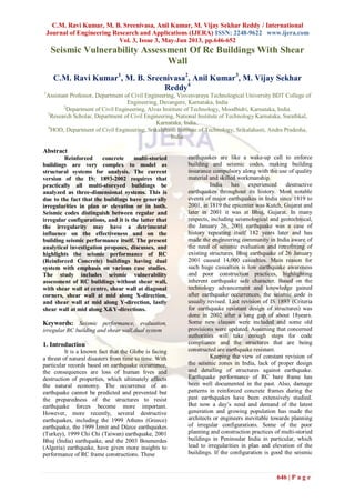
- 3. C.M. Ravi Kumar, M. B. Sreenivasa, Anil Kumar, M. Vijay Sekhar Reddy / International Journal of Engineering Research and Applications (IJERA) ISSN: 2248-9622 www.ijera.com Vol. 3, Issue 3, May-Jun 2013, pp.646-652 648 | P a g e Fig.1 Plan and 3D –View of Model 1 (Case Study 1, R=5.0, I=1.5, Z=V, S=III, Without Shear wall) a) Case Study2; Model 2; R=5.0, I=1.5, Z=V, S=III, Shear wall at centre b) Case Study3: Model 3; R=5.0, I=1.5, Z=V, S=III, Shear wall at diagonal corners
- 4. C.M. Ravi Kumar, M. B. Sreenivasa, Anil Kumar, M. Vijay Sekhar Reddy / International Journal of Engineering Research and Applications (IJERA) ISSN: 2248-9622 www.ijera.com Vol. 3, Issue 3, May-Jun 2013, pp.646-652 649 | P a g e c) Case Study4; Model 4; R=5.0, I=1.5, Z=V, S=III, Shear wall at mid along X direction d) Case Study5; Model 5; R=5.0, I=1.5, Z=V, S=III, Shear wall at mid along Y direction e) Case Study 6: Model 6; R=5.0, I=1.5, Z=V, S=III, Shear wall at mid along X&Y direction/ adjacent faces Fig 2. Location of shear wall at different position The analysis and design of multistoried building with shear wall by hand calculation is very tedious and time consuming process. So for analysis and design of each five cases as described in the problem statement is carried out with the help of structural analysis software “ETABS”. The analysis and design results are directly used of comparison. After Analysis using ETABS, the following are the results obtained as shown in Table 1. Table 1 shows the tabulation of base shear; time period, scale-up factor and storey drift values for all the models, which are noted as the various parameters to be compared with different variables. Table 1 Tabulation of base shear, time period, scale-up factor and storey drift for all the models Mode l No. Stor y Type Base Shear in KN Scale Up Time Period in Secs Maximum Story Displacem ent at Story-1 in mm Max Story Drifts of 10th floor in mm Equivalent Static Method Response Spectrum X Y X Y X Y Mod e-1 Mod e-2 Mod e-3 X Y X Y 1 G+9 1666 4 1666 4 582 5 5961 4.2 0 4.10 2.25 2.20 2.03 44 42 1.6 2 1.4 5
- 5. C.M. Ravi Kumar, M. B. Sreenivasa, Anil Kumar, M. Vijay Sekhar Reddy / International Journal of Engineering Research and Applications (IJERA) ISSN: 2248-9622 www.ijera.com Vol. 3, Issue 3, May-Jun 2013, pp.646-652 650 | P a g e 2 G+9 1649 2 1649 2 758 7 7695 3.1 9 3.14 1.71 1.69 1.65 23.9 22.9 2.7 4 2.5 3 G+9 1630 4 1630 4 834 3 8445 2.8 6 2.83 1.50 1.48 1.02 18.2 17.8 2.8 2.6 9 4 G+9 1633 7 1633 7 914 4 8551 2.6 1 2.81 1.37 1.34 1.01 14.1 10.7 2.1 9 2.4 5 5 G+9 1631 1 1631 1 835 0 8709 2.8 6 2.75 1.5 1.42 1.24 19.3 16.1 2.6 3 2.2 7 6 G+9 1631 1 1631 1 609 8 7041 3.9 2 3.39 1.64 1.45 1.09 19.6 17.9 2.5 4 2.4 Note: Response Reduction Factor, R =5.0, Importance Factor, I =1.5, Soil Type, S -III, Zone, Z= V Based on results obtained, the following plots can be drawn. Fig. 3, 4, 5, 6, 7 & 8 shows the plot of time period, base shear, and scale up factor, maximum story displacements and maximum story drifts versus different models Fig. 3. Plot of time period versus different models Fig.4. Plot of base shear versus different models Fig.5 Plot of base shear versus different models Fig. 6 Plot of scale up factor versus different models
- 6. C.M. Ravi Kumar, M. B. Sreenivasa, Anil Kumar, M. Vijay Sekhar Reddy / International Journal of Engineering Research and Applications (IJERA) ISSN: 2248-9622 www.ijera.com Vol. 3, Issue 3, May-Jun 2013, pp.646-652 651 | P a g e Fig. 7 Plot of maximum story displacements versus different models Fig. 8 Plot of maximum story drifts versus different models 3.2 Summary and Conclusions The present study makes an effort to evaluate the effect of shear wall (lift wall) at all floor for models 1-6 for Zone V, Soil type III, to study the various parameters like base shear, time period, story displacement and story drift. The study leads to the following broad conclusions: Time period will be very less when shear wall is constructed at X-direction. In other models comparatively less and high without shear wall. Time period will be less when shear wall is constructed in centre but with the consideration of first mode will be creating torsion; hence that type construction should be avoided. Scale-up factor X & Y direction will be high when no shear wall is provided, further it will decrease slightly after providing wall at different location and less when wall is provided at the X-direction. Maximum story displacement will be less when shear wall is at X direction. Comparatively less when provided in other locations and high when wall is not provided. Maximum story drift will increase slightly when shear wall is provided at different locations. By comparing all parameters with and without shear wall at all floor it is advisable to provide shear wall at X direction (as shown in model-4) for a better performance of structure. The study as a whole identifies the influencing parameters, which can regulate the effect of dual system on time period, base shear, drifts and displacements of building frames. A large number of curves exhibiting such variation for typical examples presented here can help the designer to get a primary idea about placing of lift wall in the dual system in high rise Reinforced Concrete Buildings for zone V and Soil type III. References 1. Anand S Arya (2000). „Recent Developments toward Earthquake Risk Reduction in India‟, Current Science, 12702-12777, pp. 9- 79. 2. Bungale S. Taranath S (2005). „Wind and Earthquake Resistant Buildings- Structural Analysis and Design”, CRC Press, Taylor & Francis Group, Boca Raton. 3. Clotaire Michel, Philippe Gueguen & Pierre-Yves Bard (2008). „Dynamic Parameters of Structures Extracted from Ambient Vibration Measurements:An Aid for the Seismic Vulnerability Assessment of Existing Buildings in Moderate Seismic Hazard Regions‟, Soil Dynamics and Earthquake Engineering, 28, pp. 593-604. 4. C Rudra Srinivasa Reddy and Amlan K Senugupta (2010). „Validation of Indices for Assessing Seismic Vulnerability of Multi-Storeyed Buildings with Typical Vertical Irregularities using Push–over
- 7. C.M. Ravi Kumar, M. B. Sreenivasa, Anil Kumar, M. Vijay Sekhar Reddy / International Journal of Engineering Research and Applications (IJERA) ISSN: 2248-9622 www.ijera.com Vol. 3, Issue 3, May-Jun 2013, pp.646-652 652 | P a g e Analysis‟, Journal of Structural Engineering, 4, 256-262. 5. G.M. Calvi, R. Pinho, G. Magenes, J.J. Bommer (2006). „Development of Seismic Vulnerability Assessment Methodologies over the past 30 years‟, ISET Journal of Earthquake Technology, Paper No. 472, Vol. 43, No. 3, pp. 75-104. 6. “IS-1893(Part-1) 2002). „Criteria for Earthquake Resistant Design of Structures‟, Part 1 General Provision and Buildings (Fifth Revision), Bureau of Indian Standards, New Delhi. 7. M. Ashraf, siddiqi Z.A and Javed M.A.,(2008),” Configuration of Multistory Building Subjected to Lateral Forces”, Asian Journal of Civil Enginieering,Vol.9, pp.525-537. 8. Terala Srikant, Ramancharla Pradeep Kumar, Ajay Pratap Singh, Bal Krishna Rastogi (2010). „Earthquake Vulnerability Assessment of Existing Buildings in Gandhidham and Adipur Cities Kachchh, Gujarat (India)‟, European Journal of Scientific Research, 41(3), 336-353. 9. S.K Gosh (2004). „Update on the NEHRP Provisions: The Resource Document for Seismic Design‟, PCI Journal, pp.96-102. 10. S Ganzerli, C.P.Pantelides and L. D Reaveley (2000). „Performance Based Design using Structural Optimization‟, Earthquake Engineering of Structural Dynamics, 29, pp.1677-1690. 11. V K Manicka Selvam (2011). „A Note on Preliminary Estimate of Member Dimensions of a Short Multi-storey Building Frame based on Serviceability Criterion‟, Journal of Structural Engineering, 37(5), pp. 358-363.