Mk2420552059
•
0 j'aime•812 vues

IJERA (International journal of Engineering Research and Applications) is International online, ... peer reviewed journal. For more detail or submit your article, please visit www.ijera.com

Recommandé
Contenu connexe
Tendances
Tendances (20)
En vedette
En vedette (20)
Similaire à Mk2420552059
Similaire à Mk2420552059 (20)
Mk2420552059
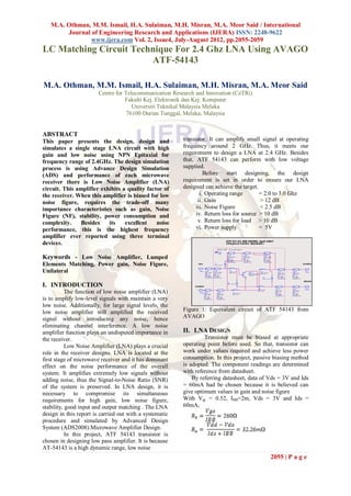
- 1. M.A. Othman, M.M. Ismail, H.A. Sulaiman, M.H. Misran, M.A. Meor Said / International Journal of Engineering Research and Applications (IJERA) ISSN: 2248-9622 www.ijera.com Vol. 2, Issue4, July-August 2012, pp.2055-2059 LC Matching Circuit Technique For 2.4 Ghz LNA Using AVAGO ATF-54143 M.A. Othman, M.M. Ismail, H.A. Sulaiman, M.H. Misran, M.A. Meor Said Centre for Telecommunication Research and Innovation (CeTRi) Fakulti Kej. Elektronik dan Kej. Komputer Universiti Teknikal Malaysia Melaka 76100 Durian Tunggal, Melaka, Malaysia ABSTRACT This paper presents the design, design and transistor. It can amplify small signal at operating simulates a single stage LNA circuit with high frequency around 2 GHz. Thus, it meets our gain and low noise using NPN Epitaxial for requirement to design a LNA at 2.4 GHz. Besides frequency range of 2.4GHz. The design simulation that, ATF 54143 can perform with low voltage process is using Advance Design Simulation supplied. (ADS) and performance of each microwave Before start designing, the design receiver there is Low Noise Amplifier (LNA) requirement is set in order to ensure our LNA circuit. This amplifier exhibits a quality factor of designed can achieve the target. the receiver. When this amplifier is biased for low i. Operating range = 2.0 to 3.0 Ghz noise figure, requires the trade-off many ii. Gain > 12 dB importance characteristics such as gain, Noise iii. Noise Figure < 2.5 dB Figure (NF), stability, power consumption and iv. Return loss for source > 10 dB complexity. Besides its excellent noise v. Return loss for load > 10 dB performance, this is the highest frequency vi. Power supply = 5V amplifier ever reported using three terminal devices. Keywords - Low Noise Amplifier, Lumped Elements Matching, Power gain, Noise Figure, Unilateral I. INTRODUCTION The function of low noise amplifier (LNA) is to amplify low-level signals with maintain a very low noise. Additionally, for large signal levels, the low noise amplifier will amplified the received Figure 1: Equivalent circuit of ATF 54143 from signal without introducing any noise, hence AVAGO eliminating channel interference. A low noise amplifier function plays an undisputed importance in II. LNA DESIGN the receiver. Transistor must be biased at appropriate Low Noise Amplifier (LNA) plays a crucial operating point before used. So that, transistor can role in the receiver designs. LNA is located at the work under values required and achieve less power first stage of microwave receiver and it has dominant consumption. In this project, passive biasing method effect on the noise performance of the overall is adopted. The component readings are determined system. It amplifies extremely low signals without with reference from datasheet. adding noise, thus the Signal-to-Noise Ratio (SNR) By referring datasheet, data of Vds = 3V and Ids of the system is preserved. In LNA design, it is = 60mA had be chosen because it is believed can necessary to compromise its simultaneous give optimum values in gain and noise figure requirements for high gain, low noise figure, With Vgs = 0.52, IBB=2m, Vds = 3V and Ids = stability, good input and output matching . The LNA 60mA, design in this report is carried out with a systematic procedure and simulated by Advanced Design System (ADS2008).Microwave Amplifier Design. In this project, ATF 54143 transistor is chosen in designing low pass amplifier. It is because AT-54143 is a high dynamic range, low noise 2055 | P a g e
- 2. M.A. Othman, M.M. Ismail, H.A. Sulaiman, M.H. Misran, M.A. Meor Said / International Journal of Engineering Research and Applications (IJERA) ISSN: 2248-9622 www.ijera.com Vol. 2, Issue4, July-August 2012, pp.2055-2059 = 56.43 = 17.52 dB Transducer gain, GT Stability Consideration The stability of an amplifier or its resistance to oscillate is an important consideration in a design. It can be determined from the S parameters. Oscillation occurs when > 1 or > 1.This is due to the dependence of and on the source and load matching networks. An amplifier Figure 2: DC biasing Circuit is said to be unconditionally stable if the auxiliary condition along with Rollet’s condition, defined as in The R1, R4 and R3 in circuit are slightly adjusted equations below, are simultaneously satisfied. from calculation readings in order to obtain better Vds and Ids reading in the simulation. Given From the data sheet, S parameter at 2.5 GHz is: (8) K = 1.11478 > 1 = 0.3427 < 1 Noise Figure Besides the stability and gain requirement, noise figure is another important consideration for a microwave amplifier. In receiver applications, it often required preamplifier with as low noise figure The reflection coefficient to source, ГS and as possible as it has dominant effect on the noise reflection coefficient to load, ГL. The equation is performance of the system. From the ATF-54143 shown in (1) and (2). datasheet, Fmin = 0.52, = 0.26 and RN/Zo = 0.04 at 2.4 GHz at 2.4 GHz (There are not reference for 2.5 GHz) Figure. 3: The General Transistor Amplifier . Circuit. = 0.52 Reflection coefficient at the load: NF = 2.769 dB Matching Network The impedance matching basic idea is presented in Fig. 2, which ensembles that an impedance matching network placed between the Since given ZL = ZS = Zo = 50Ω, the ГL and ГS load impedance and transmission line.Matching calculated as zero. Reflection coefficient at the input network is made to ideally avoid the unnecessary and output: loss power. There are variety of factors that needed to be considered in the matching network selection e.g. complexity, implementation and adjustability. In this paper, the LNA is designed by using lumped elements matching and quarter-wave transformer matching techniques. Power gain, G Figure 4: Impedance Matching Network 2056 | P a g e
- 3. M.A. Othman, M.M. Ismail, H.A. Sulaiman, M.H. Misran, M.A. Meor Said / International Journal of Engineering Research and Applications (IJERA) ISSN: 2248-9622 www.ijera.com Vol. 2, Issue4, July-August 2012, pp.2055-2059 III. RESULTS AND DISCUSSIONS A. Before Matching Figure 5: Circuit before matching Figure 6: Output load matching The parameters of noise figure, stability factor, return loss and gain values are calculated by The components reading designed by ADS using equations (1 to 9). While simulation results software are not exist in market. Thus, to fabricate, it before the matching are listed as in Table 1. must change to actual values. Parameters Calculated Simulation 0 0 1.1478 0.97 17.52 dB 17.25 dB 15.65 dB 15.31 dB 15.58 dB 15.76 dB 15.58 dB 15.63 dB NF 2.769 dB 0.375 dB LC Table 1: Results differences in calculated and matching simulation before applying matching network. circuit B. After Matching To match both impedance of input and output. Lumped elements matching is added into LNA circuit with assistance of smith chart utility in Figure 5: Circuit after matching AdS software. After matching from smitch chart, the Lumped elements circuit will automatical generated. m2 m3 freq=2.400GHz freq=2.400GHz dB(S12)=-23.066 dB(S21)=17.333 Forward and Reverse Trans., dB 19 -22.5 18 m2 m3 -23.0 dB(S12) dB(S21) 17 -23.5 16 -24.0 15 14 -24.5 2.0 2.2 2.4 2.6 2.8 3.0 freq, GHz Figure 6: S12 (isolation) and S21 (gain) Figure 5: Input source matching 2057 | P a g e
- 4. M.A. Othman, M.M. Ismail, H.A. Sulaiman, M.H. Misran, M.A. Meor Said / International Journal of Engineering Research and Applications (IJERA) ISSN: 2248-9622 www.ijera.com Vol. 2, Issue4, July-August 2012, pp.2055-2059 0 m4 The gain is also an important factor in freq=2.400GHz designing LNA for use in amplifier design. -5 dB(S(1,1))=-10.077 m4 Maximum available gain is a figure of merit for the dB(S(1,1)) -10 LNA, which indicates the maximum theoretical -15 power gain when it is conjugate matched to its -20 source and load impedances. The calculated gain is 17.52 dB compared to the simulated gain which is -25 2.0 2.2 2.4 2.6 2.8 3.0 17.25, the calculated and simulated power gain show freq, GHz almost the same result. The matching network of Figure 7: S11freq (dB) dB(S(1,1)) amplifier design is measured by the tranducer power 2.000 GHz -14.042 gain where it can be defined as separate effective 2.100 GHz -20.441 2.200 GHz m5 -17.531 gain for input (source) matching network, transistor 2.300 GHz -12.876 and the output matching network. -5 2.400 freq= 2.400GHz GHz -10.077 2.500 dB(S(2,2))=-10.442 GHz -8.269 An LNA is a design that minimizes the 2.600 GHz m5 -7.017 -10 2.700 2.800 GHz GHz -6.106 -5.420 noise figure of the system by matching the device to dB(S(2,2)) 2.900 3.000 GHz GHz -4.887 -4.465 its noise matching impedance, or Gamma optimum. -15 Gamma optimum occurs at impedance where the -20 noise of the device is terminated. All devices exhibit noise energy. To minimize the noise as seen from -25 the output port, we need to match the input load to 2.0 2.2 2.4 2.6 2.8 3.0 the conjugate noise impedance of the device. freq, GHz Otherwise, the noise will be reflected back from the Figure 8: S22 (dB) freq dB(S(2,2)) load to the device and amplified. The noise figure 2.000 GHz -5.472 passes the requirements. It can be observed that the 2.100 GHz -6.497 0.70 2.200 GHz -7.699 calculated noise figure and the simulated noise 2.300 GHz -9.027 0.65 2.400 GHz -10.442 figure is not the same. This is because the input and 2.500 GHz -11.918 output port of the network is not matched. 0.60 2.600 m8 GHz -13.445 0.55 2.700 2.800 GHz 2.400GHz freq= GHz -15.022 -16.658 For the result obtained from the simulation, the nf(2)=0.478 NFmin power gain is 17.25dB and the noise figure is nf(2) 2.900 GHz m8 -18.367 0.50 3.000 GHz -20.166 0.382dB, while the return loss for source and return 0.45 m7 loss for load is -10.077dB and -10.442dB 0.40 m7 respectively. The results obtained from the LNA 0.35 freq= 2.400GHz NFmin=0.382 simulation have achieved the requirements that have 0.30 been set. 2.0 2.1 2.2 2.3 2.4 2.5 2.6 2.7 2.8 2.9 3.0 Filter matching can be included into the freq, GHz designed circuit which is used at the output of Figure: Minimum Noise Figure (NFmin), Noise transistor method. This is used to eliminate gain at Figure (nf2) high frequencies and increase the band of operation. On the other hand, resistive loading is recommended Parameters Before Matching After Matching to have at the input as the stability of circuit can be -3.078 -10.077 dB improved. The matching procedures for input and -28.530 -10.442 dB output have to be carried out simultaneously to -25.438 -23.066dB ensure prefect matching is achieved. 14.960 17.333 dB NFmin 0.382 0.382 IV. CONCLUSION NF 0.375 0.478 A Low Noise Amplifier with given desired K 1.004 1.004 characteristics was able to design. From the Table 1: Results differences in calculated and comparison of the calculated and simulated result it simulation after applying matching network. can be seen that there is a slight difference in values. From the simulation result above, it is difficult to The stability of this transistor is design a low noise amplifier that has both low noise unconditionally stable at 2.5 GHz since its K figure and high gain together. So, it is very constant is more than 1, which is 1.004 from the important to tolerate between the input and output simulation. Therefore, no stability circle has to be matching in order to get the perfect match. drawn. Stability and maximum available gain are two of the more important considerations in ACKNOWLEDGEMENTS choosing a two-port network LNA for use in Authors would like to thank Universiti amplifier design. As used here, stability measures Teknikal Malaysia Melaka for their support in term the tendency of an LNA to oscillate. of financing to this project and also to this journal. 2058 | P a g e
- 5. M.A. Othman, M.M. Ismail, H.A. Sulaiman, M.H. Misran, M.A. Meor Said / International Journal of Engineering Research and Applications (IJERA) ISSN: 2248-9622 www.ijera.com Vol. 2, Issue4, July-August 2012, pp.2055-2059 REFERENCES [1] Jarek Lucek market application engineer and Robin Damen, “Low noise amplifier design for CDMA front end”, Philip Conductor application note. httpwww.nxp.comacrobat_downloadotherdi scretesCDMA_LNA_design.pdf [2] H.Sahoolizadeh, “Design and simulation of Low Noise Amplifier Circuit for 5 GHz to 6 GHz,” World Academy of Science, Engineering and Technology 51, 2009, pp. 99–102 [3] MIT International Journal of Electronics and Communication Engineering Vol. 1, No. 1, Jan. 2011, pp. (1-4) 1. ISSN 2230- 7672 ©MIT Publications [4] H. Hashemi, A. Hajimiri (2002). “Concurrent Multiband Low Noise AmplifiersTheory, Design and Applications”, Microwave Theory and Techniques, IEEETransactions on, Volume: 50 Issue: 1, Part: 2, Jan. 2002. 288 – 301. [5] Y. Mimino, M. Hirata, K. Nakamura, K. Sakamoto, Y. Aoki and S. uroda (2000).“High Gain Density K – band pHEMT LNA MMIC for LMDS and Satellite102 Communication”, IEEE MTT- S International Microwave Symposium Dig, IEEE, 2000. 17-20. [6] Thomas L. Floyd, Electronic Fundamentals, Sixth Edition, 2004. [7] J.S. Fairbanks, L.E. Larson (2003). “A 5 GHz Low-power, High-linearity Lownoise Amplifier in a Digital 0.35 /spl mu/m CMOS Process”, Proceedings of Radio and Wireless Conference, 2003. RAWCON '03, 10-13 August 2003. 365 – 368. [8] Gerard Wevers, “A High IIP3 Low Noise Amplifier for 1900 MHz Applications Using the SiGe BFP620 Transistor”, Infineon technologies application note, 2002. [9] David M Pozar, Microwave Engineering, Addison Wesley, 2004. [10] Agilent Technologies (2000).”Agilent ATF-54143 Low Noise Enhancement Mode Pseudomorphic HEMT in a Surface Mount Plastic Package (Data Sheet)”. USA: Agilent Technologies. pp. 1-16. [11] David M-Pozar, “Microwave Engineering” United State of America: John Wiley & Sons. INC-New, pp. 536-572. [12] Zaiki Awang, Lecture notes of RF and Microwave Design, UITM, pp.34-54,1997. [13] Annapur Das, Sisir K Das, Microwave Engineering, New Delhi, 2000. 2059 | P a g e