An automatic wave probe reference setting mechanism
•
0 j'aime•190 vues

IJRET : International Journal of Research in Engineering and Technology is an international peer reviewed, online journal published by eSAT Publishing House for the enhancement of research in various disciplines of Engineering and Technology. The aim and scope of the journal is to provide an academic medium and an important reference for the advancement and dissemination of research results that support high-level learning, teaching and research in the fields of Engineering and Technology. We bring together Scientists, Academician, Field Engineers, Scholars and Students of related fields of Engineering and Technology.

Recommandé
Recommandé
Contenu connexe
Tendances
Tendances (20)
En vedette
En vedette (20)
Similaire à An automatic wave probe reference setting mechanism
Similaire à An automatic wave probe reference setting mechanism (20)
Plus de eSAT Publishing House
Plus de eSAT Publishing House (20)
Dernier
Dernier (20)
An automatic wave probe reference setting mechanism
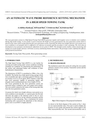
- 1. IJRET: International Journal of Research in Engineering and Technology eISSN: 2319-1163 | pISSN: 2321-7308 __________________________________________________________________________________________ Volume: 02 Issue: 09 | Sep-2013, Available @ http://www.ijret.org 515 AN AUTOMATIC WAVE PROBE REFERENCE SETTING MECHANISM IN A HIGH SPEED TOWING TANK A.Adithya Kashyap1 , B.Prasad Rao2 , Y.Srinivasa Rao3 , K.Srinivasa Rao4 1 Assistant Professor, Dept of EIE, VNRVJIET, Hyderabad, India. 2 Research Scholar, 3&4 Professor, Dept of Instrument Technology, AU College of Engineering, Vishakhapatnam, India kashyapadithya@yahoo.co.in Abstract The wave generation system in a High Speed Towing Tank (HSTT) generates regular and irregular waves to simulate wave condition during ship model testing. A wave probe is used to measure the height of waves generated by the wave generation system which is placed at the centre of the towing tank from the wave generation system. Generally the initial wave height reference (zero-point) at no wave condition is set manually and it is difficult to set reference accurately and the procedure is time consuming. The work aims at development of an automatic mechanism for adjustment of zero point in HSTT. The intended system enables remote monitoring and setting wave probe height reference with better accuracy minimizing human intervention. The prototype results confirmed the efficacy of the proposed mechanism. Keywords: Towing Tank, Wave probe, Wave generating system. --------------------------------------------------------------------***---------------------------------------------------------------------- 1. INTRODUCTION The High Speed Towing Tank (HSTT) is a test facility for carrying out model testing under various conditions including simulated sea conditions for determining the performance of the surface and submerged bodies and evaluation of their hydrodynamic characteristics. The dimensions of HSTT is considered as 500m x 8m x 8m (LxBxD). The facility has a high speed towing carriage which runs on parallel rails upto a maximum speed of 20m/sec with an accuracy of 0.1% of set speed. HSTT features a dual flap type wave generator capable of generating regular and irregular waves (unidirectional) up to wave height of 0.5m. The waves generated by the wave generation system are measured using a conductive type wave gauge (wave probe). The wave probe is placed at the centre of the towing tank 20m from the wave generation system. At present the initial wave height reference (zero-point) at no wave condition is set manually, i.e. a person goes into the tank and fixes the probe to the reference point at the no wave condition. It is difficult to set the reference accurately and the procedure is time consuming. Thus a mechanism for remote monitoring with a provision for adjustment of the reference point (‘zero’) in an HSTT is highly desired. 2. METHODOLOGY 2.1 BLOCK DIAGRAM The mechanism used in the system for setting the wave probe reference consists of two sections; Transmitter section and the Receiver section. Fig 1: Block diagram of the proposed mechanism As shown in the block diagram of the system in Fig 1, there are two microcontroller units. First unit is used to display the position of wave probe and transmit the control signal to the other microcontroller unit. The second microcontroller unit is
- 2. IJRET: International Journal of Research in Engineering and Technology eISSN: 2319-1163 | pISSN: 2321-7308 __________________________________________________________________________________________ Volume: 02 Issue: 09 | Sep-2013, Available @ http://www.ijret.org 516 used to set the position of wave probe according to the received control signal. Waves are generated by wave generation system and are measured using a wave probe which gives voltage in the range of +/-10V according to the wave level. This voltage is feed to the ADC through a cable. The microcontroller receives the digital output of the ADC. According to the digital data the microcontroller displays the position (cm) and the output voltage (V) of the wave probe which is presented on the LCD display. If the wave probe is not at the ‘zero’ reference position, the microcontroller displays other than ‘zero’ value To bring the wave probe position at ‘zero’ reference point we use a keypad by which a control signal is sent to other microcontroller unit through the transmitter. At the other microcontroller unit the receiver receives the control signal and feeds the microcontroller. According to the control signal, the microcontroller drives the stepper motor in forward or reverse direction. The wave probe is mechanically attached to the stepper motor. Therefore when the stepper motor rotates the wave probe moves upward or downward direction till the position at the ‘zero’ reference point. 2.2 CIRCUIT DETAILS As shown in the circuit in Fig 2 the 50Ω metal resister attached between REFOUT and REFIN, is used to operate in unipolar mode (i.e. 0 to +10V and 0 to +20V). In this case the BIPOFF is connected to the ground. If the BIPOFF is connected as shown in the circuit, the ADC operates bipolar input (i.e. +/-10V and +/-5V). Figure 2 Now the analog signal should be converted into the digital data and the MAX174 ADC uses a successive approximation technique to convert unknown analog input to a 12-bit digital output code according to the control signal as shown in the truth table. Table 1: Truth Table CE CS R/C 12 /8 A0 OPERATION 1 0 0 X 0 Initial 12-bit conversion 1 0 0 X 1 Initial 8-bit conversion 1 0 1 0 X Enable 12-bit parallel output 1 0 1 1 0 Enable 8-bit MSB parallel output The output of the ADC signal also depends upon the control signal as shown in the truth table. These control signals are connected to the higher nibble of port-2 of the microcontroller. The digital outputs of the ADC pins are connected to port-0 and to the lower nibble of the port-2 of microcontroller. The microcontroller receives the digital data and accordingly displays the position and the output voltage of wave probe on LCD. The LCD data pins are connected to the port-1 and the
- 3. IJRET: International Journal of Research in Engineering and Technology eISSN: 2319-1163 | pISSN: 2321-7308 __________________________________________________________________________________________ Volume: 02 Issue: 09 | Sep-2013, Available @ http://www.ijret.org 517 control signal pins of LCD are connected to the some of the port-3 of controller. For the LCD display other than ‘zero’ reference value we use normally on-off-on switch which is connected to external interrupts of the micro controller. When these push buttons are used some controlling message will pass through the serial TxD pin to the ST-FTX01-FSK transmitter module. The controlling message takes FSK modulation with 434/868MHz frequency range. This modulated signal takes the transmitter. The receiver receives the 434/868MHz range of frequency signals and demodulates the digital data. The data is given to the microcontroller through serial RxD pin. Now the microcontroller compares the controlling message by using a program. According to that data it drives the stepper motor in forward or reverse direction. But the microcontroller cannot drive the stepper motor because it does not give sufficient current to the motor. IRI44N power MOSFET is used like a driver to drive the stepper motor Figure 3 Each MOSFET is connected to microcontroller and stepper motor as shown in the Figure 3. The systems in Figure 2 and Figure 3 require individual power supply. In the power supply unit we use step down transformer to get the required voltage from the 230V AC input. This voltage is converted into DC voltage by using rectifiers (diodes like IN4007 and IN5409). The output of the rectifiers consist some amount of the ripples and to filter the AC ripples we use a smoothing capacitor. This DC voltage is regulated by the regulators according to the application. The stepper motor is allowed to the wave probe with mechanical interface as shown in Figure 4. Figure 4 The wave probe is based on a conductivity type wave gauge which comprises two thin parallel stainless steel electrodes. When immersed in water, the meter measures the conductivity of the water volume between the two electrodes that changes proportionally with the change in water surface elevation, i.e. the wave height between electrodes. 3. FLOWCHART: The wave probe reference setting is controlled by the microcontroller software. The embedded software development is carried out with the keil vision3IDE (Integrated Development Environment). By using the software we select conversion and read mode as shown in Figure 5. After the completion of the conversion the reading data is kept in two registers since the reading data is of 12-bit size. This 12-bit data should be converted into 8-bit data by using embedded software since the LCD used can receive and display 8-bit data only at a time.
- 4. IJRET: International Journal of Research in Engineering and Technology eISSN: 2319-1163 | pISSN: 2321-7308 __________________________________________________________________________________________ Volume: 02 Issue: 09 | Sep-2013, Available @ http://www.ijret.org 518 The LCD control signals are also controlled by the microcontroller software. When the program is executed it checks the interrupts every time. If any interrupt takes place then it will send data i.e. controlling data to the other microcontroller through serial communication. Here the serial communication takes place with 9600 baud rate and this baud rate can also be changed by using the program. Now the received data in other microcontroller compares. If this data equals to the reference data the microcontroller software rotates the stepper motor in the direction of reverse or forward according to the data. Otherwise the microcontroller will wait till the required data received. Figure 5 - Flowchart 4. RESULTS AND ANALYSIS: The hardware and software test is done thoroughly and the bench test is done. The output of the wave probe and the length of probe manual are compared with multi meter & vernier scale and are listed in Table 2. Table 2 The error profile plots shown in Fig 6 which are measured from the difference between the system readings and manually measured readings are obtained. Figure 6 - Error Profile plots The mechanical arrangement and the environmental conditions result in slight change in the measured values from the expected result, so the expected output is not exactly same as the system reading. The significance of these plots is that, it indicates the variation of the error value for different instances. CONCLUSIONS An automatic mechanism for remote monitoring with a provision for adjustment of reference point (“ZERO’) in a HSTT was proposed. There is an observed increase in performance with the designed system and this system adjusted the wave probe at the reference point (‘zero’) remotely. The system can be programmed to work in WAVE PROBE POSITION (cm) WAVE PROBE OUTPUT VOLTAGE (V) Scale readings (cm) System readings (cm) Multi Meter readings (V) System readings (V) 0 0.009 -0.004 0.014 0.6 0.504 0.129 0.136 1.1 1.011 0.278 0.283 2.2 2.005 0.555 0.561 3.2 3.016 0.833 0.844 5.3 5.075 1.393 1.406 10.3 10.069 2.786 2.797
- 5. IJRET: International Journal of Research in Engineering and Technology eISSN: 2319-1163 | pISSN: 2321-7308 __________________________________________________________________________________________ Volume: 02 Issue: 09 | Sep-2013, Available @ http://www.ijret.org 519 automatic mode by making changes in the program where the system checks the reference value and if there is no reference value automatically it comes to reference value. REFERENCES [1] J.Tukker, J.J.Blok, G.Kulper, R.H.M.Huijsmans, “Wake flow measurements in Towing Tanks with PIV” at 9th International symposium on Flow visualization 2000. [2] Johnson, B. and S. Enzinger, "Inexpensive Side Beaches for Improving Calm Water Testing Efficiency”, Proceedings of the 18th International Towing Tank Conference, 1987. [3] Jeng Horng Chen, Che-Chun Chang, “A moving PIV system for ship model test in a Towing tank”, Science Direct, 2006 [4] Gregory Payne, “Guidance for the experimental tank testing of wave energy converters”, Supergenmarine, University of Edinburgh [5] J.M.J. Journée and Jakob Pinkster “Introduction to Ship hydromechanics” Draft Edition, April 2002 [6] A Maggi, G Thomas and B McRae “A comparision of Numerical and Towing Tank predictions with full scale measurement” RINA International Conference, 1998.