SlideShare une entreprise Scribd logo
1  sur  4
Télécharger pour lire hors ligne
IJSRD - International Journal for Scientific Research & Development| Vol. 3, Issue 02, 2015 | ISSN (online): 2321-0613
All rights reserved by www.ijsrd.com 59
Use of Seven Quality Tools to Improve Quality and Productivity in
Industry
Pratik K. Gadre1
Devendra P Jadhav2
Shivraj G Gaikwad3
Anirudh V Jadhav4
1,2,3,4
Department of Mechanical Engineering
1,2,3,4
Smt.Kashibai Navale College of Engineering, Pune, Maharashtra
Abstract— The main aim of this paper is to provide the use
of 7-Quality Tools (QC) to improve the quality of products
in any industry. It included different methods and tools by
which some organization can keep check on quality. Some
simple techniques like basic Quality Control(QC) provide
simple and effective way to improve the quality.The work
shows continuous use of these tools upgrades the personnel
characteristics of the people involved. It enhances their
ability to think generate ideas, solve problem and do proper
planning. The development of people improves the internal
environment of the organization, Which plays a major role
in the total Quality Culture.
Key words: QC Tools, Quality Control (QC), Quality
Management (QM)
I. INTRODUCTION
Quality means freedom from deficiencies—freedom from
errors that require doing work over again (rework) or that
result in field failures, customer dissatisfaction, customer
claims, and so on. In this sense, the meaning of quality is
oriented to costs, and higher quality usually “costs less.”
Today industrial area is developing very fast. Every
day new concept and ideas are emerging out with their
relevance to industry, along with it the problems concerned
with the industrial production, quality and customers are
also increasing. It is very difficult but also important to
maintain the quality of the product in order to stay in the
market and maintain the brand name of the company or
firm.
QC is more traditional way that business have used
to manage quality. QC is concerned with checking and
reviewing work that has been done. The concept of quality
control first originated in Japan after the 2nd world war.
Later, the QC concept moved to USA, UK, and other
countries and was applied initially in the manufacturing
sector. Since then idea of QC has boosted. The 7 QC Tools
are simple statistical tools used for problem solving. These
tools were either developed in Japan or introduced to Japan
by the Quality Gurus such as Deming and Juran.
II. METHODOLOGY
In company 95% of problems can be solved using these
seven tools.
The seven Quality Tools are:
1) Check sheet
2) Flow Charts
3) Histograms
4) Pareto Analysis
5) Cause and effect diagrams(Ishikawa diagram)
6) Scatter Diagram
7) Control Chart
A. Check Sheet:
Purpose:
Check sheets allow the user to collect data from a process in
an easy, systematic, and organized manner.
1) Defective Item Check Sheet:
This type of check sheet is used to identify what types of
problems or defects are occurring in the process. Usually
these check sheets will have a list of the defects or problems
that may occur in the process. When each sample is taken, a
mark is placed in the appropriate column whenever a defect
or a problem has been identified. The type of data used in
the defective item check sheets is countable data. Table 1
below shows an example of a defective item check sheet for
the wave solder manufacturing process.
2) Defective Location Check Sheet:
This type of check sheets are used to identify the location of
the defect on the product. They are used when the external
appearance of the product is important. Usually this type of
check sheet consists of a picture of the product On this
picture, marks can be made to indicate were defects are
occurring on the surface of the product.
3) Defective Cause Check Sheet:
This type of check sheet tries to identify causes of a problem
of defect. More than one variable is monitored when
collecting data for this type of check sheets. For example,
we could be collecting data about the type of machine,
operator, fate, and time on the same check sheet.
4) Checkup Confirmation Check Sheet:
This type of check sheet is used to ensure that proper
procedure is being followed. These check sheets usually will
have a list of tasks that need to be accomplished before the
action can be taken. Examples of checkup confirmation
check sheets are final inspection, machine maintenance.
Operation checks and service performance check sheets.
B. Flow Charts:
1) Purpose:
A flow chart shows the steps in a process i.e. the actions
which transform an input to an output for the next step. This
is a significant help in analyzing a process but it must reflect
the actual process used rather than what the process owner
thinks it is or wants to be.
The differences between the actual and the intended
process are often surprising and provide many ideas for
improvements.
2) Description:
Flow Charts provide a visual illustration of the sequence of
operations required to complete a task
Fig. 2.1: Pictorial Representation of Flow Chart
A pictorial representation of a process is flowchart
Fig no.2.1.
From the picture one can overview about the inputs
and the outputs acquired from it. Every process will
require(s) to complete its task, and will provide output(s)
Use of Seven Quality Tools to Improve Quality and Productivity in Industry
(IJSRD/Vol. 3/Issue 02/2015/015)
All rights reserved by www.ijsrd.com 60
when the task is completed. For example, an injection
molding machine requires inputs in the form of raw material
and proper machine settings to be able to produce a proper
part. The output of the injection molding process is the
finished part.
Flow charts can be drawn in many styles. They can
be drawn by using picture, engineering symbols, or just
squares and rectangles. The, flow charts can be used to
describe a single process, parts of a process, or a set of
processes.
C. Histograms:
Purpose:
To determine the spread or variation of a set of data points
in a graphical form.
Fig. 2.2: Histogram
D. Pareto Charts:
1) Purpose:
The purpose of the Pareto chart is to prioritize problems-to
decide what problems must be addressed. No company has
enough resources to tackle every problem, so they must
prioritize.
The purpose of this report is to inform the reader of the
Pareto principles and how it can be applied to the
manufacturing environment.
2) Pareto Principle:
The Pareto concept was developed by the Italian
economist Wilfred Pareto describing the frequency
distribution of any given characteristic of a population. It is
also called as the 20-80 rule.
He determined that a small percentage of any given
group (20%) account for a high amount of a certain
characteristic (80%). The Pareto chart is especially helpful
in improving manufacturing processes.
3) Pareto Analysis:
Pareto analysis is based on principle of 80-20 i.e. 20% of
problem cause 80% of the trouble.
Fig. 2.3: Parreto Analysis
In above graph, start from 80% on Y-axis and mark point on
cumulative graph. Draw a perpendicular on X-axis and
identify 20% of causes for 80% of rejections (e.g. A and B
in the above fig.). Take care of defects A and B using cause
and effect diagram or such tools to reduce rejections.
E. Cause-and-Effect Diagram:
1) Purpose:
One important part of the process improvement is
continuously striving to obtain more important about the
process and its output. Cause-and-effect diagrams allow us
to do not just that but also can lead us to the root cause or
causes of problems. It is a tool that enables the user to set
down systematically a graphical representation of the trail
that leads ultimately to the root cause of a quality concern or
problem.
2) Description:
Its basic aim of fish bone diagram is to find out major as
well as minor causes of quality problems, under the 4 M
approach: Materials, Machines, Manpower and Methods.
1) Manpower: People’s behavior and attitudes.
2) Methods: The way activities are carried out.
3) Machinery: what people work with?
4) Material: what people work on?
Fig. 2.4: Cuase Effect Diagram
F. Scatter Diagram:
1) Purpose:
To identify correlations that might exist between a quality
characteristic and a factor might be driving it.
Also called: scatter plot, X�Y graph
2) Description:
The scatter diagram graphs pairs of numerical data, with one
variable on each axis, to look for a relationship between
them. If the variables are correlated, the points will fall
along a line or curve. The better the correlation, the tighter
the points will hug the line.
3) When to Use a Scatter Diagram
 When you have paired numerical data
 When your dependent variable may have multiple
values for each value of your independent variable
 When trying to determine whether the two
variables are related, such as…
 When trying to identify potential root causes
of problems.
 After brainstorming causes and effects using a
fishbone diagram, to determine objectively
whether a particular cause and effect are
related
 When determining whether two effects that
appear to be related both occur with the same
cause
Use of Seven Quality Tools to Improve Quality and Productivity in Industry
(IJSRD/Vol. 3/Issue 02/2015/015)
All rights reserved by www.ijsrd.com 61
 When testing for autocorrelation before
constructing a control chart.
4) Scatter Diagram Procedure:
1) Collect pairs of data where a relationship is
suspected.
2) Draw a graph with the independent variable on the
horizontal axis and the dependent variable on the
vertical axis. For each pair of data, put a dot or a
symbol where the x-axis value intersects the y-axis
value. (If two dots fall together, put them side by
side, touching, so that you can see both.)
3) Look at the pattern of points to see if a relationship
is obvious. If the data clearly form a line or a curve,
you may stop. The variables are correlated. You
may wish to use regression or correlation analysis
now. Otherwise, complete steps 4 through 7.
4) Divide points on the graph into four quadrants. If
there are X points on the graph,
 Count X/2 points from top to bottom and
draw a horizontal line.
 Count X/2 points from left to right and
draw a vertical line.
 If number of points is odd, draw the line
through the middle point.
5) Count the points in each quadrant. Do not count
points on a line.
6) Add the diagonally opposite quadrants. Find the
smaller sum and the total of points in all quadrants.
 A = point sin upper left + points in lower right
B = points in upper right + points in lower left
Q = the smaller of A and B
N = A + B
7) Look up the limit for N on the trend test table.
 If Q is less than the limit, the two variables are
related.
 If Q is greater than or equal to the limit, the
pattern could have occurred from random
chance.
5) Scatter Diagram Example:
The ZZ-400 manufacturing team suspects a relationship
between product purity (percent purity) and the amount of
iron (measured in parts per million or ppm). Purity and iron
are plotted against each other as a scatter diagram, as shown
in the figure below.
There are 24 data points. Median lines are drawn so that 12
points fall on each side for both percent purity and ppm iron.
Then they look up the limit for N on the trend test
table. For N = 24, the limit is 6.
Q is equal to the limit. Therefore, the pattern could
have occurred from random chance, and no relationship is
demonstrated.
Fig. 2.5: Scatter Diagram Example
G. Control Chart:
Also called: statistical process control
1) Description:
The control chart is a graph used to study how a process
changes over time. Data are plotted in time order. A control
chart always has a central line for the average, an upper line
for the upper control limit and a lower line for the lower
control limit. These lines are determined from historical
data. By comparing current data to these lines, you can draw
conclusions about whether the process variation is consistent
(in control) or is unpredictable (out of control, affected by
special causes of variation).
Control charts for variable data are used in pairs.
The top chart monitors the average, or the centering of the
distribution of data from the process. The bottom chart
monitors the range, or the width of the distribution. If your
data were shots in target practice, the average is where the
shots are clustering, and the range is how tightly they are
clustered. Control charts for attribute data are used singly.
2) When to Use a Control Chart:
 When controlling ongoing processes by finding and
correcting problems as they occur.
 When predicting the expected range of outcomes
from a process.
 When determining whether a process is stable (in
statistical control).
 When analyzing patterns of process variation from
special causes (non-routine events) or common
causes (built into the process).
 When determining whether your quality
improvement project should aim to prevent specific
problems or to make fundamental changes to the
process.
3) Control Chart Basic Procedure:
1) Choose the appropriate control chart for your data.
2) Determine the appropriate time period for
collecting and plotting data.
3) Collect data, construct your chart and analyze the
data.
4) Look for “out-of-control signals” on the control
chart. When one is identified, mark it on the chart
and investigate the cause. Document how you
investigated, what you learned, the cause and how
it was corrected.
4) Out-Of-Control Signals:
 A single point outside the control limits. In Figure
1, point sixteen is above the UCL (upper control
limit).
Use of Seven Quality Tools to Improve Quality and Productivity in Industry
(IJSRD/Vol. 3/Issue 02/2015/015)
All rights reserved by www.ijsrd.com 62
 Two out of three successive points are on the same
side of the centerline and farther than 2 σ from it.
In Figure 1, point 4 sends that signal.
 Four out of five successive points are on the same
side of the centerline and farther than 1 σ from it.
In Figure 1, point 11 sends that signal.
 A run of eight in a row are on the same side of the
centerline. Or 10 out of 11, 12 out of 14 or 16 out
of 20. In Figure 1, point 21 is eighth in a row above
the centerline.
 Obvious consistent or persistent patterns that
suggest something unusual about your data and
your process.
Fig. 2.6: Control Chart: Out-Of-Control Signals
5) Continue to plot data as they are generated. As
each new data point is plotted, check for new out-
of-control signals.
6) When you start a new control chart, the process
may be out of control. If so, the control limits
calculated from the first 20 points are conditional
limits. When you have at least 20 sequential points
from a period when the process is operating in
control, recalculate control limits.
III. CONCLUSION
Seven QC tools are most helpful in troubleshooting issues
related to quality. It has been observed that by application of
seven Quality tools performance of company has improved
drastically by 95%. Selection of Quality control technique
has influenced three factors: ease of use of technique, ability
to measure product specification fulfillment, ability to
improve critical quality and productivity problems.
Quality tools has important place in data collecting,
analyzing, visualizing and making sound base for data
founded decision making.
The development of quality tools has been
successful in providing customers with more consistent and
quality products. In short, 7 Quality Tools have proofed to
be useful in enhancing the development of industry.
REFERENCES
[1] Juran J. M., 1974, Quality Control Handbook,
McGraw Hill, New York.
[2] Walker, H. F and Levesque, J. 'The Innovation
Process and Quality Tools', Quality Progress, Vol.
40, No. 7, July 2007, pp. 18/22
[3] Pratik J. Patel*, Sanjay C. Shah**, Sanjay
Makwana [Int. Journal of Engineering Research
and Applications www.ijera.com ISSN: 2248-9622,
Vol. 4, Issue 2( Version 1), February 2014, pp.129-
134 ]
[4] Powell, T.C., (1995). Total quality management as
competitive advantage: a review and empirical
study. Strategic Management Journal, 16(1), 15-27.
[5] Oakland, J.S. and Leslie, J.P., (1996). Total Quality
Management-Text with Cases, Great Britain,
Martins: The Printer.

Contenu connexe

Tendances

Cause and effect diagram
Cause and effect diagramCause and effect diagram
Cause and effect diagram
Lizzette Danan
 
Problem solving tools 112411
Problem solving tools 112411Problem solving tools 112411
Problem solving tools 112411
Khriztel NaTsu
 
7 qc tools training material[1]
7 qc tools training material[1]7 qc tools training material[1]
7 qc tools training material[1]
gurmukh singh
 
Spc lecture presentation (bonnie corrror)
Spc lecture presentation (bonnie corrror)Spc lecture presentation (bonnie corrror)
Spc lecture presentation (bonnie corrror)
Jitesh Gaurav
 

Tendances (20)

Production and Quality Tools: The 7 Basic Quality Tools
Production and Quality Tools: The 7 Basic Quality ToolsProduction and Quality Tools: The 7 Basic Quality Tools
Production and Quality Tools: The 7 Basic Quality Tools
 
Fisbone Diagrams Assgnmnt1
Fisbone Diagrams Assgnmnt1Fisbone Diagrams Assgnmnt1
Fisbone Diagrams Assgnmnt1
 
Ishikawa fishbone diagram
Ishikawa fishbone diagramIshikawa fishbone diagram
Ishikawa fishbone diagram
 
Cause and effect diagram
Cause and effect diagramCause and effect diagram
Cause and effect diagram
 
Quality Control Tools for Problem Solving
Quality Control Tools for Problem SolvingQuality Control Tools for Problem Solving
Quality Control Tools for Problem Solving
 
Problem solving tools 112411
Problem solving tools 112411Problem solving tools 112411
Problem solving tools 112411
 
Quality tools in JUST 2 HOURS !!
Quality tools in JUST 2 HOURS !!Quality tools in JUST 2 HOURS !!
Quality tools in JUST 2 HOURS !!
 
7 qc tools
7 qc tools7 qc tools
7 qc tools
 
7 qc tools basic
7 qc tools basic7 qc tools basic
7 qc tools basic
 
Basic 8D Problem Solving Tools & Methods - Part 2
Basic 8D Problem Solving Tools & Methods - Part 2Basic 8D Problem Solving Tools & Methods - Part 2
Basic 8D Problem Solving Tools & Methods - Part 2
 
7 qc tools training material[1]
7 qc tools training material[1]7 qc tools training material[1]
7 qc tools training material[1]
 
Fishbone diagam guide
Fishbone diagam guideFishbone diagam guide
Fishbone diagam guide
 
Qc story
Qc storyQc story
Qc story
 
Spc lecture presentation (bonnie corrror)
Spc lecture presentation (bonnie corrror)Spc lecture presentation (bonnie corrror)
Spc lecture presentation (bonnie corrror)
 
7 QC Tools 7 Quality Tools Process Improvement Tools.pdf
7 QC Tools 7 Quality Tools Process Improvement Tools.pdf7 QC Tools 7 Quality Tools Process Improvement Tools.pdf
7 QC Tools 7 Quality Tools Process Improvement Tools.pdf
 
7 qc tools
7 qc tools7 qc tools
7 qc tools
 
7 qc tools
7 qc tools7 qc tools
7 qc tools
 
Seven tools of quality for pmp exam
Seven tools of quality for pmp examSeven tools of quality for pmp exam
Seven tools of quality for pmp exam
 
Control Charts[1]
Control Charts[1]Control Charts[1]
Control Charts[1]
 
Statistical quality control 1,2
Statistical quality control 1,2Statistical quality control 1,2
Statistical quality control 1,2
 

En vedette

A Survey of Modern Character Recognition Techniques
A Survey of Modern Character Recognition TechniquesA Survey of Modern Character Recognition Techniques
A Survey of Modern Character Recognition Techniques
ijsrd.com
 

En vedette (15)

Messaging Gateway
Messaging GatewayMessaging Gateway
Messaging Gateway
 
Machining of Sic - Metal Matrix Composite (MMC) by Polycrystalline Diamond (P...
Machining of Sic - Metal Matrix Composite (MMC) by Polycrystalline Diamond (P...Machining of Sic - Metal Matrix Composite (MMC) by Polycrystalline Diamond (P...
Machining of Sic - Metal Matrix Composite (MMC) by Polycrystalline Diamond (P...
 
Experimental Investigation on Use of Honge(Pongamia) Biodiesel on Multi-cylin...
Experimental Investigation on Use of Honge(Pongamia) Biodiesel on Multi-cylin...Experimental Investigation on Use of Honge(Pongamia) Biodiesel on Multi-cylin...
Experimental Investigation on Use of Honge(Pongamia) Biodiesel on Multi-cylin...
 
An Impact of Land use and Transportation - A case study of Sanand Area
An Impact of Land use and Transportation - A case study of Sanand AreaAn Impact of Land use and Transportation - A case study of Sanand Area
An Impact of Land use and Transportation - A case study of Sanand Area
 
Ijsrdv1 i2070Experimental Investigations of Chemical and Geotechnical Propert...
Ijsrdv1 i2070Experimental Investigations of Chemical and Geotechnical Propert...Ijsrdv1 i2070Experimental Investigations of Chemical and Geotechnical Propert...
Ijsrdv1 i2070Experimental Investigations of Chemical and Geotechnical Propert...
 
A Survey of Modern Character Recognition Techniques
A Survey of Modern Character Recognition TechniquesA Survey of Modern Character Recognition Techniques
A Survey of Modern Character Recognition Techniques
 
A NEW PROPOSED SYMMETRIC KEY ALGORITHM FOR MODERN CRYPTOGRAPHIC
A NEW PROPOSED SYMMETRIC KEY ALGORITHM FOR MODERN CRYPTOGRAPHICA NEW PROPOSED SYMMETRIC KEY ALGORITHM FOR MODERN CRYPTOGRAPHIC
A NEW PROPOSED SYMMETRIC KEY ALGORITHM FOR MODERN CRYPTOGRAPHIC
 
Approximation of Gaussian derivatives for UWB communication
Approximation of Gaussian derivatives for UWB communicationApproximation of Gaussian derivatives for UWB communication
Approximation of Gaussian derivatives for UWB communication
 
Design and Simulation Low power SRAM Circuits
Design and Simulation Low power SRAM CircuitsDesign and Simulation Low power SRAM Circuits
Design and Simulation Low power SRAM Circuits
 
A Novel Technique to Solve Mathematical Model of Pressure Swing Adsorption Sy...
A Novel Technique to Solve Mathematical Model of Pressure Swing Adsorption Sy...A Novel Technique to Solve Mathematical Model of Pressure Swing Adsorption Sy...
A Novel Technique to Solve Mathematical Model of Pressure Swing Adsorption Sy...
 
Detecting Wormhole Attack in Mobile Ad-hoc Networks: A Survey
Detecting Wormhole Attack in Mobile Ad-hoc Networks: A SurveyDetecting Wormhole Attack in Mobile Ad-hoc Networks: A Survey
Detecting Wormhole Attack in Mobile Ad-hoc Networks: A Survey
 
A New Transmission Scheme for MIMO – OFDM
A New Transmission Scheme for MIMO – OFDMA New Transmission Scheme for MIMO – OFDM
A New Transmission Scheme for MIMO – OFDM
 
Simulation of 3 bit Flash ADC in 0.18μmTechnology using NG SPICE Tool for Hig...
Simulation of 3 bit Flash ADC in 0.18μmTechnology using NG SPICE Tool for Hig...Simulation of 3 bit Flash ADC in 0.18μmTechnology using NG SPICE Tool for Hig...
Simulation of 3 bit Flash ADC in 0.18μmTechnology using NG SPICE Tool for Hig...
 
Optimization of Process Parameters of Tungsten Inert Gas Welding by Taguchi M...
Optimization of Process Parameters of Tungsten Inert Gas Welding by Taguchi M...Optimization of Process Parameters of Tungsten Inert Gas Welding by Taguchi M...
Optimization of Process Parameters of Tungsten Inert Gas Welding by Taguchi M...
 
Operations management
Operations management Operations management
Operations management
 

Similaire à Use of Seven Quality Tools to Improve Quality and Productivity in Industry

Quality management in software engineering
Quality management in software engineeringQuality management in software engineering
Quality management in software engineering
selinasimpson1201
 
TQM UNIT 2.pptx presentation with images
TQM UNIT 2.pptx presentation with imagesTQM UNIT 2.pptx presentation with images
TQM UNIT 2.pptx presentation with images
Pradeep482741
 
L07 quality management
L07 quality managementL07 quality management
L07 quality management
Asa Chan
 

Similaire à Use of Seven Quality Tools to Improve Quality and Productivity in Industry (20)

Em33832837
Em33832837Em33832837
Em33832837
 
Review on Quality Management using 7 QC Tools
Review on Quality Management using 7 QC ToolsReview on Quality Management using 7 QC Tools
Review on Quality Management using 7 QC Tools
 
S4201129134
S4201129134S4201129134
S4201129134
 
Quality Improvement Of Fan Manufacturing Industry By Using Basic Seven Tools ...
Quality Improvement Of Fan Manufacturing Industry By Using Basic Seven Tools ...Quality Improvement Of Fan Manufacturing Industry By Using Basic Seven Tools ...
Quality Improvement Of Fan Manufacturing Industry By Using Basic Seven Tools ...
 
Quality Improvement Of Fan Manufacturing Industry By Using Basic Seven Tools ...
Quality Improvement Of Fan Manufacturing Industry By Using Basic Seven Tools ...Quality Improvement Of Fan Manufacturing Industry By Using Basic Seven Tools ...
Quality Improvement Of Fan Manufacturing Industry By Using Basic Seven Tools ...
 
IRJET- A Survey: Quality Control Tool in Auto Parts Industry
IRJET- A Survey: Quality Control Tool in Auto Parts IndustryIRJET- A Survey: Quality Control Tool in Auto Parts Industry
IRJET- A Survey: Quality Control Tool in Auto Parts Industry
 
7 quality control tools
7 quality  control tools7 quality  control tools
7 quality control tools
 
New 7QC tools for the quality person during RCa
New 7QC tools for the quality person during RCaNew 7QC tools for the quality person during RCa
New 7QC tools for the quality person during RCa
 
Final pp of mqc.pptx
Final pp of mqc.pptxFinal pp of mqc.pptx
Final pp of mqc.pptx
 
Run Chart
Run ChartRun Chart
Run Chart
 
Quality management in software engineering
Quality management in software engineeringQuality management in software engineering
Quality management in software engineering
 
Quality control and inspection
Quality control and inspectionQuality control and inspection
Quality control and inspection
 
TQM UNIT 2.pptx presentation with images
TQM UNIT 2.pptx presentation with imagesTQM UNIT 2.pptx presentation with images
TQM UNIT 2.pptx presentation with images
 
7 QC(Quality Control) Tools
7 QC(Quality Control) Tools7 QC(Quality Control) Tools
7 QC(Quality Control) Tools
 
Total Quality tools
Total Quality toolsTotal Quality tools
Total Quality tools
 
IMPLEMENTATION OF STATISTICAL PROCESS CONTROL TOOL IN AN AUTOMOBILE MANUFACTU...
IMPLEMENTATION OF STATISTICAL PROCESS CONTROL TOOL IN AN AUTOMOBILE MANUFACTU...IMPLEMENTATION OF STATISTICAL PROCESS CONTROL TOOL IN AN AUTOMOBILE MANUFACTU...
IMPLEMENTATION OF STATISTICAL PROCESS CONTROL TOOL IN AN AUTOMOBILE MANUFACTU...
 
Spc
SpcSpc
Spc
 
L07 quality management
L07 quality managementL07 quality management
L07 quality management
 
Seven Basic Tools of QC and their Applications
Seven Basic Tools of QC and their ApplicationsSeven Basic Tools of QC and their Applications
Seven Basic Tools of QC and their Applications
 
7 QC Tools for data analysis and problem solving
7 QC Tools for data analysis and problem solving7 QC Tools for data analysis and problem solving
7 QC Tools for data analysis and problem solving
 

Plus de ijsrd.com

Plus de ijsrd.com (20)

IoT Enabled Smart Grid
IoT Enabled Smart GridIoT Enabled Smart Grid
IoT Enabled Smart Grid
 
A Survey Report on : Security & Challenges in Internet of Things
A Survey Report on : Security & Challenges in Internet of ThingsA Survey Report on : Security & Challenges in Internet of Things
A Survey Report on : Security & Challenges in Internet of Things
 
IoT for Everyday Life
IoT for Everyday LifeIoT for Everyday Life
IoT for Everyday Life
 
Study on Issues in Managing and Protecting Data of IOT
Study on Issues in Managing and Protecting Data of IOTStudy on Issues in Managing and Protecting Data of IOT
Study on Issues in Managing and Protecting Data of IOT
 
Interactive Technologies for Improving Quality of Education to Build Collabor...
Interactive Technologies for Improving Quality of Education to Build Collabor...Interactive Technologies for Improving Quality of Education to Build Collabor...
Interactive Technologies for Improving Quality of Education to Build Collabor...
 
Internet of Things - Paradigm Shift of Future Internet Application for Specia...
Internet of Things - Paradigm Shift of Future Internet Application for Specia...Internet of Things - Paradigm Shift of Future Internet Application for Specia...
Internet of Things - Paradigm Shift of Future Internet Application for Specia...
 
A Study of the Adverse Effects of IoT on Student's Life
A Study of the Adverse Effects of IoT on Student's LifeA Study of the Adverse Effects of IoT on Student's Life
A Study of the Adverse Effects of IoT on Student's Life
 
Pedagogy for Effective use of ICT in English Language Learning
Pedagogy for Effective use of ICT in English Language LearningPedagogy for Effective use of ICT in English Language Learning
Pedagogy for Effective use of ICT in English Language Learning
 
Virtual Eye - Smart Traffic Navigation System
Virtual Eye - Smart Traffic Navigation SystemVirtual Eye - Smart Traffic Navigation System
Virtual Eye - Smart Traffic Navigation System
 
Ontological Model of Educational Programs in Computer Science (Bachelor and M...
Ontological Model of Educational Programs in Computer Science (Bachelor and M...Ontological Model of Educational Programs in Computer Science (Bachelor and M...
Ontological Model of Educational Programs in Computer Science (Bachelor and M...
 
Understanding IoT Management for Smart Refrigerator
Understanding IoT Management for Smart RefrigeratorUnderstanding IoT Management for Smart Refrigerator
Understanding IoT Management for Smart Refrigerator
 
DESIGN AND ANALYSIS OF DOUBLE WISHBONE SUSPENSION SYSTEM USING FINITE ELEMENT...
DESIGN AND ANALYSIS OF DOUBLE WISHBONE SUSPENSION SYSTEM USING FINITE ELEMENT...DESIGN AND ANALYSIS OF DOUBLE WISHBONE SUSPENSION SYSTEM USING FINITE ELEMENT...
DESIGN AND ANALYSIS OF DOUBLE WISHBONE SUSPENSION SYSTEM USING FINITE ELEMENT...
 
A Review: Microwave Energy for materials processing
A Review: Microwave Energy for materials processingA Review: Microwave Energy for materials processing
A Review: Microwave Energy for materials processing
 
Web Usage Mining: A Survey on User's Navigation Pattern from Web Logs
Web Usage Mining: A Survey on User's Navigation Pattern from Web LogsWeb Usage Mining: A Survey on User's Navigation Pattern from Web Logs
Web Usage Mining: A Survey on User's Navigation Pattern from Web Logs
 
APPLICATION OF STATCOM to IMPROVED DYNAMIC PERFORMANCE OF POWER SYSTEM
APPLICATION OF STATCOM to IMPROVED DYNAMIC PERFORMANCE OF POWER SYSTEMAPPLICATION OF STATCOM to IMPROVED DYNAMIC PERFORMANCE OF POWER SYSTEM
APPLICATION OF STATCOM to IMPROVED DYNAMIC PERFORMANCE OF POWER SYSTEM
 
Making model of dual axis solar tracking with Maximum Power Point Tracking
Making model of dual axis solar tracking with Maximum Power Point TrackingMaking model of dual axis solar tracking with Maximum Power Point Tracking
Making model of dual axis solar tracking with Maximum Power Point Tracking
 
A REVIEW PAPER ON PERFORMANCE AND EMISSION TEST OF 4 STROKE DIESEL ENGINE USI...
A REVIEW PAPER ON PERFORMANCE AND EMISSION TEST OF 4 STROKE DIESEL ENGINE USI...A REVIEW PAPER ON PERFORMANCE AND EMISSION TEST OF 4 STROKE DIESEL ENGINE USI...
A REVIEW PAPER ON PERFORMANCE AND EMISSION TEST OF 4 STROKE DIESEL ENGINE USI...
 
Study and Review on Various Current Comparators
Study and Review on Various Current ComparatorsStudy and Review on Various Current Comparators
Study and Review on Various Current Comparators
 
Reducing Silicon Real Estate and Switching Activity Using Low Power Test Patt...
Reducing Silicon Real Estate and Switching Activity Using Low Power Test Patt...Reducing Silicon Real Estate and Switching Activity Using Low Power Test Patt...
Reducing Silicon Real Estate and Switching Activity Using Low Power Test Patt...
 
Defending Reactive Jammers in WSN using a Trigger Identification Service.
Defending Reactive Jammers in WSN using a Trigger Identification Service.Defending Reactive Jammers in WSN using a Trigger Identification Service.
Defending Reactive Jammers in WSN using a Trigger Identification Service.
 

Dernier

1029-Danh muc Sach Giao Khoa khoi 6.pdf
1029-Danh muc Sach Giao Khoa khoi  6.pdf1029-Danh muc Sach Giao Khoa khoi  6.pdf
1029-Danh muc Sach Giao Khoa khoi 6.pdf
QucHHunhnh
 
Making and Justifying Mathematical Decisions.pdf
Making and Justifying Mathematical Decisions.pdfMaking and Justifying Mathematical Decisions.pdf
Making and Justifying Mathematical Decisions.pdf
Chris Hunter
 
The basics of sentences session 2pptx copy.pptx
The basics of sentences session 2pptx copy.pptxThe basics of sentences session 2pptx copy.pptx
The basics of sentences session 2pptx copy.pptx
heathfieldcps1
 

Dernier (20)

1029-Danh muc Sach Giao Khoa khoi 6.pdf
1029-Danh muc Sach Giao Khoa khoi  6.pdf1029-Danh muc Sach Giao Khoa khoi  6.pdf
1029-Danh muc Sach Giao Khoa khoi 6.pdf
 
Basic Civil Engineering first year Notes- Chapter 4 Building.pptx
Basic Civil Engineering first year Notes- Chapter 4 Building.pptxBasic Civil Engineering first year Notes- Chapter 4 Building.pptx
Basic Civil Engineering first year Notes- Chapter 4 Building.pptx
 
Micro-Scholarship, What it is, How can it help me.pdf
Micro-Scholarship, What it is, How can it help me.pdfMicro-Scholarship, What it is, How can it help me.pdf
Micro-Scholarship, What it is, How can it help me.pdf
 
TỔNG ÔN TẬP THI VÀO LỚP 10 MÔN TIẾNG ANH NĂM HỌC 2023 - 2024 CÓ ĐÁP ÁN (NGỮ Â...
TỔNG ÔN TẬP THI VÀO LỚP 10 MÔN TIẾNG ANH NĂM HỌC 2023 - 2024 CÓ ĐÁP ÁN (NGỮ Â...TỔNG ÔN TẬP THI VÀO LỚP 10 MÔN TIẾNG ANH NĂM HỌC 2023 - 2024 CÓ ĐÁP ÁN (NGỮ Â...
TỔNG ÔN TẬP THI VÀO LỚP 10 MÔN TIẾNG ANH NĂM HỌC 2023 - 2024 CÓ ĐÁP ÁN (NGỮ Â...
 
Measures of Dispersion and Variability: Range, QD, AD and SD
Measures of Dispersion and Variability: Range, QD, AD and SDMeasures of Dispersion and Variability: Range, QD, AD and SD
Measures of Dispersion and Variability: Range, QD, AD and SD
 
Asian American Pacific Islander Month DDSD 2024.pptx
Asian American Pacific Islander Month DDSD 2024.pptxAsian American Pacific Islander Month DDSD 2024.pptx
Asian American Pacific Islander Month DDSD 2024.pptx
 
Presentation by Andreas Schleicher Tackling the School Absenteeism Crisis 30 ...
Presentation by Andreas Schleicher Tackling the School Absenteeism Crisis 30 ...Presentation by Andreas Schleicher Tackling the School Absenteeism Crisis 30 ...
Presentation by Andreas Schleicher Tackling the School Absenteeism Crisis 30 ...
 
Python Notes for mca i year students osmania university.docx
Python Notes for mca i year students osmania university.docxPython Notes for mca i year students osmania university.docx
Python Notes for mca i year students osmania university.docx
 
On National Teacher Day, meet the 2024-25 Kenan Fellows
On National Teacher Day, meet the 2024-25 Kenan FellowsOn National Teacher Day, meet the 2024-25 Kenan Fellows
On National Teacher Day, meet the 2024-25 Kenan Fellows
 
Role Of Transgenic Animal In Target Validation-1.pptx
Role Of Transgenic Animal In Target Validation-1.pptxRole Of Transgenic Animal In Target Validation-1.pptx
Role Of Transgenic Animal In Target Validation-1.pptx
 
Holdier Curriculum Vitae (April 2024).pdf
Holdier Curriculum Vitae (April 2024).pdfHoldier Curriculum Vitae (April 2024).pdf
Holdier Curriculum Vitae (April 2024).pdf
 
How to Give a Domain for a Field in Odoo 17
How to Give a Domain for a Field in Odoo 17How to Give a Domain for a Field in Odoo 17
How to Give a Domain for a Field in Odoo 17
 
This PowerPoint helps students to consider the concept of infinity.
This PowerPoint helps students to consider the concept of infinity.This PowerPoint helps students to consider the concept of infinity.
This PowerPoint helps students to consider the concept of infinity.
 
Application orientated numerical on hev.ppt
Application orientated numerical on hev.pptApplication orientated numerical on hev.ppt
Application orientated numerical on hev.ppt
 
Ecological Succession. ( ECOSYSTEM, B. Pharmacy, 1st Year, Sem-II, Environmen...
Ecological Succession. ( ECOSYSTEM, B. Pharmacy, 1st Year, Sem-II, Environmen...Ecological Succession. ( ECOSYSTEM, B. Pharmacy, 1st Year, Sem-II, Environmen...
Ecological Succession. ( ECOSYSTEM, B. Pharmacy, 1st Year, Sem-II, Environmen...
 
Food Chain and Food Web (Ecosystem) EVS, B. Pharmacy 1st Year, Sem-II
Food Chain and Food Web (Ecosystem) EVS, B. Pharmacy 1st Year, Sem-IIFood Chain and Food Web (Ecosystem) EVS, B. Pharmacy 1st Year, Sem-II
Food Chain and Food Web (Ecosystem) EVS, B. Pharmacy 1st Year, Sem-II
 
Making and Justifying Mathematical Decisions.pdf
Making and Justifying Mathematical Decisions.pdfMaking and Justifying Mathematical Decisions.pdf
Making and Justifying Mathematical Decisions.pdf
 
The basics of sentences session 2pptx copy.pptx
The basics of sentences session 2pptx copy.pptxThe basics of sentences session 2pptx copy.pptx
The basics of sentences session 2pptx copy.pptx
 
Web & Social Media Analytics Previous Year Question Paper.pdf
Web & Social Media Analytics Previous Year Question Paper.pdfWeb & Social Media Analytics Previous Year Question Paper.pdf
Web & Social Media Analytics Previous Year Question Paper.pdf
 
Class 11th Physics NEET formula sheet pdf
Class 11th Physics NEET formula sheet pdfClass 11th Physics NEET formula sheet pdf
Class 11th Physics NEET formula sheet pdf
 

Use of Seven Quality Tools to Improve Quality and Productivity in Industry

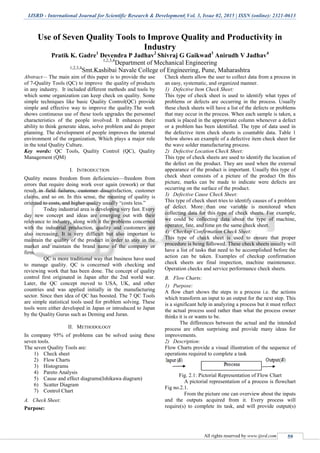
  • 1. IJSRD - International Journal for Scientific Research & Development| Vol. 3, Issue 02, 2015 | ISSN (online): 2321-0613 All rights reserved by www.ijsrd.com 59 Use of Seven Quality Tools to Improve Quality and Productivity in Industry Pratik K. Gadre1 Devendra P Jadhav2 Shivraj G Gaikwad3 Anirudh V Jadhav4 1,2,3,4 Department of Mechanical Engineering 1,2,3,4 Smt.Kashibai Navale College of Engineering, Pune, Maharashtra Abstract— The main aim of this paper is to provide the use of 7-Quality Tools (QC) to improve the quality of products in any industry. It included different methods and tools by which some organization can keep check on quality. Some simple techniques like basic Quality Control(QC) provide simple and effective way to improve the quality.The work shows continuous use of these tools upgrades the personnel characteristics of the people involved. It enhances their ability to think generate ideas, solve problem and do proper planning. The development of people improves the internal environment of the organization, Which plays a major role in the total Quality Culture. Key words: QC Tools, Quality Control (QC), Quality Management (QM) I. INTRODUCTION Quality means freedom from deficiencies—freedom from errors that require doing work over again (rework) or that result in field failures, customer dissatisfaction, customer claims, and so on. In this sense, the meaning of quality is oriented to costs, and higher quality usually “costs less.” Today industrial area is developing very fast. Every day new concept and ideas are emerging out with their relevance to industry, along with it the problems concerned with the industrial production, quality and customers are also increasing. It is very difficult but also important to maintain the quality of the product in order to stay in the market and maintain the brand name of the company or firm. QC is more traditional way that business have used to manage quality. QC is concerned with checking and reviewing work that has been done. The concept of quality control first originated in Japan after the 2nd world war. Later, the QC concept moved to USA, UK, and other countries and was applied initially in the manufacturing sector. Since then idea of QC has boosted. The 7 QC Tools are simple statistical tools used for problem solving. These tools were either developed in Japan or introduced to Japan by the Quality Gurus such as Deming and Juran. II. METHODOLOGY In company 95% of problems can be solved using these seven tools. The seven Quality Tools are: 1) Check sheet 2) Flow Charts 3) Histograms 4) Pareto Analysis 5) Cause and effect diagrams(Ishikawa diagram) 6) Scatter Diagram 7) Control Chart A. Check Sheet: Purpose: Check sheets allow the user to collect data from a process in an easy, systematic, and organized manner. 1) Defective Item Check Sheet: This type of check sheet is used to identify what types of problems or defects are occurring in the process. Usually these check sheets will have a list of the defects or problems that may occur in the process. When each sample is taken, a mark is placed in the appropriate column whenever a defect or a problem has been identified. The type of data used in the defective item check sheets is countable data. Table 1 below shows an example of a defective item check sheet for the wave solder manufacturing process. 2) Defective Location Check Sheet: This type of check sheets are used to identify the location of the defect on the product. They are used when the external appearance of the product is important. Usually this type of check sheet consists of a picture of the product On this picture, marks can be made to indicate were defects are occurring on the surface of the product. 3) Defective Cause Check Sheet: This type of check sheet tries to identify causes of a problem of defect. More than one variable is monitored when collecting data for this type of check sheets. For example, we could be collecting data about the type of machine, operator, fate, and time on the same check sheet. 4) Checkup Confirmation Check Sheet: This type of check sheet is used to ensure that proper procedure is being followed. These check sheets usually will have a list of tasks that need to be accomplished before the action can be taken. Examples of checkup confirmation check sheets are final inspection, machine maintenance. Operation checks and service performance check sheets. B. Flow Charts: 1) Purpose: A flow chart shows the steps in a process i.e. the actions which transform an input to an output for the next step. This is a significant help in analyzing a process but it must reflect the actual process used rather than what the process owner thinks it is or wants to be. The differences between the actual and the intended process are often surprising and provide many ideas for improvements. 2) Description: Flow Charts provide a visual illustration of the sequence of operations required to complete a task Fig. 2.1: Pictorial Representation of Flow Chart A pictorial representation of a process is flowchart Fig no.2.1. From the picture one can overview about the inputs and the outputs acquired from it. Every process will require(s) to complete its task, and will provide output(s)
  • 2. Use of Seven Quality Tools to Improve Quality and Productivity in Industry (IJSRD/Vol. 3/Issue 02/2015/015) All rights reserved by www.ijsrd.com 60 when the task is completed. For example, an injection molding machine requires inputs in the form of raw material and proper machine settings to be able to produce a proper part. The output of the injection molding process is the finished part. Flow charts can be drawn in many styles. They can be drawn by using picture, engineering symbols, or just squares and rectangles. The, flow charts can be used to describe a single process, parts of a process, or a set of processes. C. Histograms: Purpose: To determine the spread or variation of a set of data points in a graphical form. Fig. 2.2: Histogram D. Pareto Charts: 1) Purpose: The purpose of the Pareto chart is to prioritize problems-to decide what problems must be addressed. No company has enough resources to tackle every problem, so they must prioritize. The purpose of this report is to inform the reader of the Pareto principles and how it can be applied to the manufacturing environment. 2) Pareto Principle: The Pareto concept was developed by the Italian economist Wilfred Pareto describing the frequency distribution of any given characteristic of a population. It is also called as the 20-80 rule. He determined that a small percentage of any given group (20%) account for a high amount of a certain characteristic (80%). The Pareto chart is especially helpful in improving manufacturing processes. 3) Pareto Analysis: Pareto analysis is based on principle of 80-20 i.e. 20% of problem cause 80% of the trouble. Fig. 2.3: Parreto Analysis In above graph, start from 80% on Y-axis and mark point on cumulative graph. Draw a perpendicular on X-axis and identify 20% of causes for 80% of rejections (e.g. A and B in the above fig.). Take care of defects A and B using cause and effect diagram or such tools to reduce rejections. E. Cause-and-Effect Diagram: 1) Purpose: One important part of the process improvement is continuously striving to obtain more important about the process and its output. Cause-and-effect diagrams allow us to do not just that but also can lead us to the root cause or causes of problems. It is a tool that enables the user to set down systematically a graphical representation of the trail that leads ultimately to the root cause of a quality concern or problem. 2) Description: Its basic aim of fish bone diagram is to find out major as well as minor causes of quality problems, under the 4 M approach: Materials, Machines, Manpower and Methods. 1) Manpower: People’s behavior and attitudes. 2) Methods: The way activities are carried out. 3) Machinery: what people work with? 4) Material: what people work on? Fig. 2.4: Cuase Effect Diagram F. Scatter Diagram: 1) Purpose: To identify correlations that might exist between a quality characteristic and a factor might be driving it. Also called: scatter plot, X�Y graph 2) Description: The scatter diagram graphs pairs of numerical data, with one variable on each axis, to look for a relationship between them. If the variables are correlated, the points will fall along a line or curve. The better the correlation, the tighter the points will hug the line. 3) When to Use a Scatter Diagram  When you have paired numerical data  When your dependent variable may have multiple values for each value of your independent variable  When trying to determine whether the two variables are related, such as…  When trying to identify potential root causes of problems.  After brainstorming causes and effects using a fishbone diagram, to determine objectively whether a particular cause and effect are related  When determining whether two effects that appear to be related both occur with the same cause
  • 3. Use of Seven Quality Tools to Improve Quality and Productivity in Industry (IJSRD/Vol. 3/Issue 02/2015/015) All rights reserved by www.ijsrd.com 61  When testing for autocorrelation before constructing a control chart. 4) Scatter Diagram Procedure: 1) Collect pairs of data where a relationship is suspected. 2) Draw a graph with the independent variable on the horizontal axis and the dependent variable on the vertical axis. For each pair of data, put a dot or a symbol where the x-axis value intersects the y-axis value. (If two dots fall together, put them side by side, touching, so that you can see both.) 3) Look at the pattern of points to see if a relationship is obvious. If the data clearly form a line or a curve, you may stop. The variables are correlated. You may wish to use regression or correlation analysis now. Otherwise, complete steps 4 through 7. 4) Divide points on the graph into four quadrants. If there are X points on the graph,  Count X/2 points from top to bottom and draw a horizontal line.  Count X/2 points from left to right and draw a vertical line.  If number of points is odd, draw the line through the middle point. 5) Count the points in each quadrant. Do not count points on a line. 6) Add the diagonally opposite quadrants. Find the smaller sum and the total of points in all quadrants.  A = point sin upper left + points in lower right B = points in upper right + points in lower left Q = the smaller of A and B N = A + B 7) Look up the limit for N on the trend test table.  If Q is less than the limit, the two variables are related.  If Q is greater than or equal to the limit, the pattern could have occurred from random chance. 5) Scatter Diagram Example: The ZZ-400 manufacturing team suspects a relationship between product purity (percent purity) and the amount of iron (measured in parts per million or ppm). Purity and iron are plotted against each other as a scatter diagram, as shown in the figure below. There are 24 data points. Median lines are drawn so that 12 points fall on each side for both percent purity and ppm iron. Then they look up the limit for N on the trend test table. For N = 24, the limit is 6. Q is equal to the limit. Therefore, the pattern could have occurred from random chance, and no relationship is demonstrated. Fig. 2.5: Scatter Diagram Example G. Control Chart: Also called: statistical process control 1) Description: The control chart is a graph used to study how a process changes over time. Data are plotted in time order. A control chart always has a central line for the average, an upper line for the upper control limit and a lower line for the lower control limit. These lines are determined from historical data. By comparing current data to these lines, you can draw conclusions about whether the process variation is consistent (in control) or is unpredictable (out of control, affected by special causes of variation). Control charts for variable data are used in pairs. The top chart monitors the average, or the centering of the distribution of data from the process. The bottom chart monitors the range, or the width of the distribution. If your data were shots in target practice, the average is where the shots are clustering, and the range is how tightly they are clustered. Control charts for attribute data are used singly. 2) When to Use a Control Chart:  When controlling ongoing processes by finding and correcting problems as they occur.  When predicting the expected range of outcomes from a process.  When determining whether a process is stable (in statistical control).  When analyzing patterns of process variation from special causes (non-routine events) or common causes (built into the process).  When determining whether your quality improvement project should aim to prevent specific problems or to make fundamental changes to the process. 3) Control Chart Basic Procedure: 1) Choose the appropriate control chart for your data. 2) Determine the appropriate time period for collecting and plotting data. 3) Collect data, construct your chart and analyze the data. 4) Look for “out-of-control signals” on the control chart. When one is identified, mark it on the chart and investigate the cause. Document how you investigated, what you learned, the cause and how it was corrected. 4) Out-Of-Control Signals:  A single point outside the control limits. In Figure 1, point sixteen is above the UCL (upper control limit).
  • 4. Use of Seven Quality Tools to Improve Quality and Productivity in Industry (IJSRD/Vol. 3/Issue 02/2015/015) All rights reserved by www.ijsrd.com 62  Two out of three successive points are on the same side of the centerline and farther than 2 σ from it. In Figure 1, point 4 sends that signal.  Four out of five successive points are on the same side of the centerline and farther than 1 σ from it. In Figure 1, point 11 sends that signal.  A run of eight in a row are on the same side of the centerline. Or 10 out of 11, 12 out of 14 or 16 out of 20. In Figure 1, point 21 is eighth in a row above the centerline.  Obvious consistent or persistent patterns that suggest something unusual about your data and your process. Fig. 2.6: Control Chart: Out-Of-Control Signals 5) Continue to plot data as they are generated. As each new data point is plotted, check for new out- of-control signals. 6) When you start a new control chart, the process may be out of control. If so, the control limits calculated from the first 20 points are conditional limits. When you have at least 20 sequential points from a period when the process is operating in control, recalculate control limits. III. CONCLUSION Seven QC tools are most helpful in troubleshooting issues related to quality. It has been observed that by application of seven Quality tools performance of company has improved drastically by 95%. Selection of Quality control technique has influenced three factors: ease of use of technique, ability to measure product specification fulfillment, ability to improve critical quality and productivity problems. Quality tools has important place in data collecting, analyzing, visualizing and making sound base for data founded decision making. The development of quality tools has been successful in providing customers with more consistent and quality products. In short, 7 Quality Tools have proofed to be useful in enhancing the development of industry. REFERENCES [1] Juran J. M., 1974, Quality Control Handbook, McGraw Hill, New York. [2] Walker, H. F and Levesque, J. 'The Innovation Process and Quality Tools', Quality Progress, Vol. 40, No. 7, July 2007, pp. 18/22 [3] Pratik J. Patel*, Sanjay C. Shah**, Sanjay Makwana [Int. Journal of Engineering Research and Applications www.ijera.com ISSN: 2248-9622, Vol. 4, Issue 2( Version 1), February 2014, pp.129- 134 ] [4] Powell, T.C., (1995). Total quality management as competitive advantage: a review and empirical study. Strategic Management Journal, 16(1), 15-27. [5] Oakland, J.S. and Leslie, J.P., (1996). Total Quality Management-Text with Cases, Great Britain, Martins: The Printer.