2. 330 Beshahwired Ayalew, Bohdan T. Kulakowski / ISA Transactions 44 (2005) 329–343
3. Beshahwired Ayalew, Bohdan T. Kulakowski / ISA Transactions 44 (2005) 329–343 331
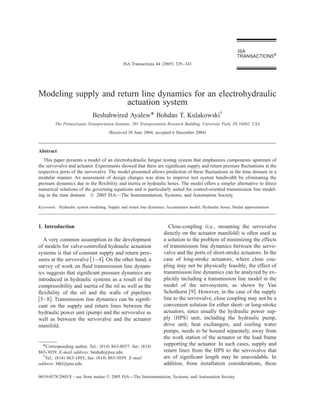
Fig. 1. Schematic of test system ͑HPϭhigh pressure, LPϭlow pressure͒.
supply and return lines are usually flexible hoses output stage. The servovalve is close coupled with
rated for the appropriate working pressure. a 10-kN, 102-mm-stroke symmetric actuator,
Aside from the extensive presentation by Vier- which is mounted on a load frame. Pressure trans-
sma ͓7͔, not much has been reported on the analy- ducers are used for sensing the pressures at the
sis of a hydraulic servosystem including supply four ports of the servovalve. A linear variable dif-
pressure variations at the servovalve. Viersma’s ferential transformer ͑LVDT͒ is mounted on the
analysis was done in the frequency domain and the actuator piston for position measurement.
emphasis was to provide design rules for the loca- Control and signal processing is done with a
tion and sizing of the components of hydraulic ser- dSpace® 1104 single processor board, which in-
vosystems. Yang and Tobler ͓10͔ developed a cludes onboard A/D and D/A converters and a
modal approximation technique that enables slave digital signal processor ͑DSP͒. An amplifier
analysis of fluid transmission lines in the time do- circuit converts a 0–10-V control output from the
main via state space formulations. Modal approxi- dSpace® D/A to a high-impedance Ϯ50-mA cur-
mation results provide modular and simpler alter- rent input to the torque motor coils of the servov-
natives to direct numerical time-domain solutions alve.
of the flow equations. The unit labeled hydraulic services manifold
In this paper, the authors present and use modal ͑HSM͒ is connected to the servovalve using 3.048-
approximation results within a model of an elec- m-long SAE-100R2 hoses. The hydraulic power
trohydraulic actuation system to investigate supply supply ͑HPS͒ unit, including its heat exchanger
and return pressure variations at the servovalve and drive units, is housed separately and is con-
due to transmission line dynamics. Open-loop and nected to the HSM via 3.048-m-long SAE-100R2
closed-loop tests were conducted to validate the hoses. The HSM provides basic line pressure regu-
model. The model was then used to make a quick lation via the accumulators. In addition, the HSM
evaluation of alternative layouts of the supply and is equipped with a control manifold circuitry to
return lines. permit selection of high- and low-pressure operat-
ing modes, low-pressure level adjustment, slow
2. Description of test system pressure turn-on and turn-off, and fast pressure un-
loading. The drain line provides a path for oil that
The hydraulic system shown schematically in seeps past the seals in the actuator and also for
Fig. 1 was designed for fatigue testing applica- draining oil from the HSM pressure gage.
tions. The servovalve is a 5-gpm ͑19 lpm͒ two- During a normal fatigue testing operation, both
stage servovalve employing a torque motor driven the low-pressure and high-pressure solenoids are
double nozzle-flapper first stage and a main spool energized, the main control valve is completely
4. 332 Beshahwired Ayalew, Bohdan T. Kulakowski / ISA Transactions 44 (2005) 329–343
Fig. 2. Simplified system.
wide open, and the circuitry of the HSM allows pressed from the pump output pressure. Therefore,
flow at full system pressure ͓11͔. We therefore in the following analysis, it is assumed that the
model the HSM by considering the lumped non- output pressure just after the accumulator and
linear resistance arising from change of flow di- pressure relief valve connection points in the HPS
rections, flow cross sections, as well as flow in the unit can be set as a known pressure input to the
filter element. The total pressure drop between the rest of the system. In fact, this is not a very restric-
pressure inlet and outlet ports of the HSM is given tive assumption, since the modeling approach pre-
in manufacturer specifications. The available data sented here is modular and models of the upstream
satisfy a nonlinear expression relating flow rate to components of the whole HPS unit can be incor-
pressure drop. While the HSM unit is rated for a porated if needed.
wide range of flow rate capacities, the rated flow For the simplified system, we now have two sec-
rate through the servovalve is within 10% of tions of transmission hoses to model. The first sec-
nominal flow rate of the HSM. We therefore use a tion is for the supply and return hoses between the
local linear approximation to account for losses in HPS and the HSM and the second is for the hoses
the HSM, between the HSM and the servovalve. A model
applicable for each section is discussed next.
⌬p HSM ϭR HSM q. ͑1͒
We further assume that the check valve is an 3. Model of transmission lines
ideal one, so that its own dynamics are fast enough
to be neglected and its backflow restriction has a To model the hydraulic hoses for our system, we
large enough parallel resistance that the permitted refer to previous rigorous results on validated so-
backflow is very small. We also consider the drain lutions of the mass and momentum conservation
flow to be negligible. With these simplifications, equations governing flow in one-dimensional fluid
the system reduces to the one shown in Fig. 2. It transmission lines having a circular cross section
should be noted that the resistances were lumped ͓5,6,8͔. In general, some assumptions are neces-
in the HSM excluding the gas-charged accumula- sary for the basic results to hold. These assump-
tors. tions include laminar flow in the lines, negligible
We make one more assumption before we pro- gravitational effects, negligible tangential velocity,
ceed. Through extensive frequency domain analy- and negligible variations of pressure and density
sis, Viersma ͓7͔ has shown that, provided that the in the radial and tangential directions. We also as-
accumulator and the pressure relief valve on the sume constant and uniform temperature and ignore
hydraulic power supply unit are located suffi- heat transfer effects in the fluid line. We thereby
ciently close to the pump outlet ͑within 0.3 m͒, the limit the discussion to the linear friction model,
pump flow pulsation frequencies can be sup- which does not include distributed viscosity and
5. Beshahwired Ayalew, Bohdan T. Kulakowski / ISA Transactions 44 (2005) 329–343 333
other input ͓12͔. Since we have already assumed
the pressure just after the connection point of the
pressure relief valve and first accumulator to be
taken as an input to the system, the desired causal
Fig. 3. A fluid transmission line. form of the four-pole equations for the supply line
is the so-called pressure-input/pressure-output
causality form ͓15͔. It can be derived by defining
the boundary conditions for the distributed param-
heat transfer effects ͓6,10͔. Corrections are applied eter model as the upstream pressure and flow rate
to account for the frequency dependence of vis- ( p u ,q d ) and the downstream pressure and flow
cosity on the linear friction model, following the rate ( p d ,q u ) at the opposite ends of the line,
work of Yang and Tobler ͓10͔.
The flow lines are assumed to have rigid walls
in some derivations ͓1,7͔. However, Blackburn et
al. ͓12͔ and McCloy and Martin ͓13͔ arrive at the
ͫ ͬ
P d͑ s ͒
Q u͑ s ͒
ͫ ͬ
same governing equations as the rigid wall case 1 Z c ͑ s ͒ sinh ⌫ ͑ s ͒
͑for a frictionless flow͒ by allowing for wall flex- Ϫ
cosh ⌫ ͑ s ͒ cosh ⌫ ͑ s ͒
ibility and defining an effective bulk modulus ϭ
combining the flexibility of the wall and that of sinh ⌫ ͑ s ͒ 1
the oil. Their definition of effective bulk modulus Z c ͑ s ͒ cosh ⌫ ͑ s ͒ cosh ⌫ ͑ s ͒
is the same as that derived by Merritt ͓4͔, where
the effective bulk modulus is viewed as a series
interconnection of the ‘‘stiffness’’ of the oil, of a
ͫ ͬ
P u͑ s ͒
ϫ Q s͒ .
d͑
͑2͒
container wall and even of entrapped air volume in
the oil. Following this approach, we consider flex- The definitions of the propagation operator ⌫ ( s )
ibility effects via the effective bulk modulus  e . and the line characteristic impedance Z c ( s ) de-
The model parameters required for any section of pend on the friction model chosen ͓6,9͔. In this
the transmission line reduce to the ones shown in paper, the authors use the approach of Yang and
Fig. 3. For the hydraulic hoses in this work, nomi- Tobler ͓10͔ that incorporated frequency-dependent
nal values of the bulk modulus were taken from damping and natural frequency modification fac-
Ref. ͓13͔. tors into analytically derived modal representa-
Using the above assumptions for the single tions of the four-pole equations for the linear fric-
transmission line, the conservation laws can be in- tion model. ⌫ ( s ) and Z c ( s ) are defined by
tegrated in the Laplace domain to yield a well-
known distributed parameter model commonly ex-
pressed as a two-port matrix equation and
⌫ ͑ s ͒ ϭD n
d 2s
4
ͱ ␣ 2ϩ
32␣
sd 2
, ͑3͒
sometimes known as the four-pole equation ͓1,7͔.
The four-pole equations can take four physically
realizable causal forms ͓6,9,12͔. Two of these four
are readily relevant to the problem at hand: one for
Z c ͑ s ͒ ϭZ 0 ͱ 32␣
sd 2
ϩ ␣ 2. ͑4͒
the supply line hoses and another one for the re-
turn line hoses. The third one also finds use with The frequency-dependent correction factors ␣
accumulator connection lines, as discussed by Ay- and  are obtained by comparing the modal un-
alew and Kulakowski ͓14͔. damped natural frequencies and damping coeffi-
Taking the supply line case first, we notice that cients of the modal approximations of the dissipa-
in most hydraulic servosystem applications, a con- tive ͑‘‘exact’’͒ model, which is described in detail
trol signal modulates the servovalve consumption in Ref. ͓16͔, against the modal representation of
flow rate downstream of the supply line, q d ( t ) , the linear friction model ͓10͔. Corrected kinematic
following the excursions of the ͑loaded͒ actuator viscosity ͑͒ values are used ͓8͔. The dimension-
piston. Then q d ( t ) is a preferred input to the trans- less numbers D n and Z 0 are the dissipation num-
mission line model, and a realizable causality form ber and the line impedance constant, respectively,
requires that either p u ( t ) or q u ( t ) should be the and are given by
6. 334 Beshahwired Ayalew, Bohdan T. Kulakowski / ISA Transactions 44 (2005) 329–343
ͫ ͬ
n
4l
D nϭ , ͑5͒ ͚ p di
cd 2
ͫ ͬ
pd
qu ϭ
iϭ1
n ϭ ͓ I 2 I 2 ¯I 2 ͔
4c iϭ1
͚ q ui
Z 0ϭ , ͑6͒
d2 ϫ͓ p d1 q u1 p d2 q u2 ¯p dn q un ͔ .
͑10͒
where c is the speed of sound in the oil,
It should be noted that the truncation to finite
number of modes will introduce steady-state er-
cϭ ͱ . e
͑7͒ rors. Some methods have been suggested to re-
cover the steady-state output based on the fact that
at steady state the original four-pole equation, Eq.
The three causal functions 1/cosh ⌫(s), ͑2͒, reduces to
Z c ( s ) sinh ⌫(s)/cosh ⌫(s), and sinh ⌫(s)/
Zc(s)cosh ⌫(s) can be represented as infinite sums
of quadratic modal transfer functions. The goal is ͫ ͬ ͫ
pd
qu ss
ϭ
1
0
Ϫ8D n p u
1 qd ͬͫ ͬ ss
. ͑11͒
to use a finite number of modes to approximate the
otherwise infinite sum of the modal contributions Hsue and Hullender ͓16͔ discussed rescaling the
for the outputs. Of particular interest for the time truncated sum of the modal approximation for the
domain models sought in this paper is the state dissipative model by its zero-frequency magnitude
space formulation ͓10,15͔, to bring about Eq. ͑11͒. Van Schothorst ͓9͔ and
Hullender et al. ͓15͔ described an additive ap-
ͫ ͬͫ ͬ
0 ͑ Ϫ1 ͒ iϩ1 Z 0 ci proach where the steady-state error is eliminated
ͫ ͬ
˙ di
p
q ui ϭ Ϫ
˙ ͑ Ϫ1 ͒ iϩ1 ci
2
Ϫ 2
32 
p di
q ui
by adding a corrective feed-through term on the
output equation ͑10͒. However, the transfer func-
tions so implemented will no longer be strictly
Z 0␣ d ␣
ͫ ͬ
proper. This may entail the need for off-line alge-
8Z0 braic manipulations when the transmission line is
0 Ϫ connected to static source and/or load linear resis-
ϩ
8
d 2D n
ͫ ͬ
pu
qd ,
tances or other transmission line models with their
own direct feed-through gains. The eigenvalues of
0 the coupled system may then be altered by the
d 2Z 0D n␣ 2 steady-state correction ͓15͔.
Yang and Tobler ͓10͔ introduced methods that
iϭ1,2,3...n. ͑8͒ modify the input-matrix or use a state similarity
transformation matrix to affect the steady-state
The ci are the modal undamped natural frequen- correction while preserving the modal eigenvalues
cies of blocked line for the linear friction model of the truncated model. Since comparable results
given by are obtained by the use of either method, we adopt
the input-matrix modification method here. Sup-
ͩ ͪ
pose matrices A i and B i represent, respectively,
1
4 iϪ the feedback and input matrices in the modal state
2 space Eq. ͑8͒. Introducing the input-matrix modi-
ci ϭ , iϭ1,2,3,...n. ͑9͒
d 2D n fier G,
The modification factors ␣ and  are given as
functions of the dimensionless modal frequencies
ͫ ͬ ͫ ͬ
˙
p di
q
p di pu
˙ ui ϭA i q ui ϩB i G q d . ͫ ͬ ͑12͒
d 2 ci /4 ͓10͔. The output is the sum of the modal The steady-state value of the n-mode approxima-
contributions and is expressed as tion is then
7. Beshahwired Ayalew, Bohdan T. Kulakowski / ISA Transactions 44 (2005) 329–343 335
ͫ ͬ ͫ ͬ ͫ ͬ
n n
pd p di pu
qu ϭ͚ q ui ϭϪ ͚ ͑ A Ϫ1 B i ͒ G q
i .
ss iϭ1 ss iϭ1 d ss
͑13͒
Comparing with the desired steady-state value
given by Eq. ͑11͒ and solving for G,
GϭϪ ͚ͩ n
iϭ1
A Ϫ1 B i
i ͪͫ
Ϫ1
1
0
Ϫ8Z 0 D n
1
ͬ . ͑14͒
The number of modes n to be chosen depends on
the frequency range of interest for the application.
Similarly, for the return line from the servo-
valve, we can define the flow rate at the servov-
alve end and the pressure at the downstream ͑to-
ward the tank͒ end as inputs to the model of the
return line based on the other four-pole equation
of causality dual to Eq. ͑2͒ ͓6͔. Equally, we can
use the observation that switching the sign con-
vention of the flow direction for just the return line
and using the four-pole equation dual to Eq. ͑2͒
yields the same set of four-pole equations as Eq. Fig. 4. Piston accumulator.
͑2͒, provided the inputs to the model remain flow
rate toward the servovalve end and pressure at the
other end. This fact can easily be shown math- plied after initial transients have died down. In
ematically, but we omit it here for brevity and general ‘‘steady’’ simulations, like those involving
state that for the return line model all of the deri- sinusoidal fatigue test wave forms, the modal ini-
vations presented above for modeling the supply tial conditions of the interconnected system are
line hold. The caveat is to exercise care in using less important.
the proper signs for the input and output flow rates As shown in Fig. 3, the model described in this
at both ends of the return line when forming inter- section requires few parameters to set up and
connections with other system components. simulate each transmission line section using lin-
For step response simulations, it is desirable to ear state space models in the time domain. This is
have good estimates of the initial conditions of the particularly more convenient than finite difference
modal states, especially when the interconnected approaches, which may require rigorous descreti-
system model contains nonlinearities. Usually, for zation methods.
a single pipeline section, the derivative of the
modal output can be assumed to be zero just be-
fore the application of the step change in the input, 4. Modeling accumulators
and modal initial conditions can be computed
from For the nitrogen gas-charged accumulators,
which are of piston type for our system ͑Fig. 4͒,
ͫ p di ͑ 0 Ϫ ͒
q ui ͑ 0 Ϫ ͒ͬ i ͫ
p u͑ 0 Ϫ ͒
ϭϪA Ϫ1 B i G q 0 Ϫ ͒ ,
d͑
ͬ ͑15͒
we assume that the piston mass and seal friction
are negligible. Under this assumption, the gas
pressure and the oil pressure are equal. We also
where the ͓ p u ( 0 Ϫ ) ,q d ( 0 Ϫ ) ͔ T are the inputs just neglect the compressibility of the oil volume in
before the step change. For an interconnected the accumulator compared to the compressibility
pipeline system, the inputs to one pipeline section of the gas. Furthermore, we consider the gas to
may be outputs of another section, in which case undergo a polytropic expansion and compression
the determination of proper initial values for the process with polytropic exponent m.
modal states of each section can be done by trial
and error. The step disturbances can also be ap- p g V m ϭconst.
g ͑16͒
8. 336 Beshahwired Ayalew, Bohdan T. Kulakowski / ISA Transactions 44 (2005) 329–343
Fig. 5. Model interconnections for the supply line ͑Version I͒.
The exponent m approaches 1 for a slow ͑nearly can be estimated as the HSM pressure minus the
isothermal͒ process and the specific heat ratio of pressure drop in the connection lines.
the gas for a rapid ͑adiabatic͒ process on an ideal
gas. However, it should be noted that if heat trans-
fer effects were to be included, then real gas equa- 5. Model interconnections for the supply line
tions of state should be used together with appro-
priate energy conservation laws. For the work The components on the supply line of the sim-
presented here, the present model was found to be plified model shown in Fig. 2 can be intercon-
sufficiently accurate. nected as shown in Figs. 5 or 6. The arrows indi-
Given initial gas pressure p g0 and gas volume, cate the input-output causality assigned for each
V g0 , the gas pressure is computed from Eq. ͑16͒, subsystem. Each of the blocks section I and sec-
which is equivalent to tion II implement Eqs. ͑8͒–͑14͒ for the corre-
sponding sections of the supply line.
mpg Integration causality is the desired form for the
˙
p gϭ qa , p g ͑ 0 ͒ ϭp g0 , ͑17͒ model of the accumulator, which is given by Eq.
V g0 Ϫ ͐ t0 q a dt ͑17͒. It was pointed out by Viersma ͓7͔ that the
where q a is the flow rate of the hydraulic oil to the flow dynamics in the short branch-away connec-
accumulator. For simulations involving distur- tion lines to the accumulators are significant in
bances applied at the servovalve, it is reasonable most cases. Under the linear resistance assumption
to assume that the accumulator already develops given by Eq. ͑1͒, the subsystem ‘‘manifold and
an initial gas pressure through a slow isothermal check valve loss’’ can be configured either as a
process1 ( mϭ1 ) . The initial gas volume V g0 can pressure-input/flow rate-output subsystem ͑in ver-
be estimated by applying Eq. ͑16͒ between the sion I, Fig. 5͒ or as a pressure-input/pressure-
pre-charge state ͑the gas pre-charge pressure at ac- output subsystem ͑in version II, Fig. 6͒. As a con-
cumulator capacity͒ and the initial state at the on- sequence, the model of the short accumulator
set of the disturbance. The initial gas pressure p g0 connection line changes between version I and
version II. The model of the short connection line
1 in version I has the same structure as the one de-
The present system has an additional slow turn-on/turn-
off accumulator that enables the HSM to come to full sys-
scribed above for the sections of the main supply
tem pressure from an off state in a slow and controlled line. The model for the short connection line in
manner. The servovalve disturbances considered in this version II is derived using the modal approxima-
study are applied after the whole system has reached nor- tion for the relevant four-pole equations with
mal operating conditions. ( p u ,p d ) as input and ( q u ,q d ) as output, as de-
9. Beshahwired Ayalew, Bohdan T. Kulakowski / ISA Transactions 44 (2005) 329–343 337
Fig. 6. Model interconnections for the supply line ͑Version II͒.
scribed by Ayalew and Kulakowski ͓14͔. It was 6. Model for servovalve and actuator
shown there that the dynamics of the short connec-
tion line can be approximated by a first-order term Physical models of electrohydraulic servoactua-
that reduces to a series interconnection of hydrau- tors are quite widely available in the literature
lic resistance and inertance. This result goes along ͓1– 4,7,9,17͔. The model presented here is adapted
with the convenient assumption that the oil side to apply to a four-way servovalve close coupled
compressibility in the accumulator is negligible with a double-ended piston actuator.
compared to that of the gas side. This result also Fig. 7 shows a double-ended translational piston
makes version II preferable to version I, since it actuator with hydraulic flow rates q t from the top
reduces the order of the overall system and verifies chamber and q b to the bottom chamber of the cyl-
a physically supported model order reduction. inder. Leakage flow between the two chambers is
The model for the return line is developed in a either internal ( q i ) between the two chambers or
similar way noting the reverse direction of the external from the top chamber ( q e,t ) and from the
flow, as mentioned earlier. It should be noted that bottom chamber ( q e,b ) . A t and A b represent the
the modularity of the subsystem model intercon- effective piston areas of the top and bottom face,
nections allows changes to be made to the system respectively. V t and V b are the volumes of oil in
model with ease. the top and bottom chamber of the cylinder, re-
spectively, corresponding to the center position
( x p ϭ0 ) of the piston. These volumes are also
considered to include the respective volumes of oil
in the pipelines between the close-coupled servo-
valve and actuator as well as the small volumes in
the servovalve itself.
We assume that the pressure dynamics in the
lines between the servovalve and the actuator are
negligible due to the close coupling.2 Furthermore,
even for a long-stroke actuator used in a flight
simulator application, Van Schothorst ͓9͔ has
2
This is to say that any resonances introduced by the
short-length lines are well above the frequency range of
interest for our system. In fact, this can be verified using
the model development presented earlier or referring to the
Fig. 7. Schematic of a rectilinear actuator and servovalve. results of Van Schothorst ͓9͔.
10. 338 Beshahwired Ayalew, Bohdan T. Kulakowski / ISA Transactions 44 (2005) 329–343
shown that the pressure dynamics in the actuator
chambers need not be modeled using distributed
parameter models. It is therefore assumed that the
pressure is uniform in each cylinder chamber and
is the same as the pressure at the respective port of
the servovalve.
Starting with the continuity equation and intro-
ducing the state equation with the effective bulk
modulus for the cylinder chambers, it can be Fig. 8. Actuator with a simple load model.
shown that the pressure dynamics are given by
͑see, for example Ref. ͓2͔͒
dpb c
ϭ ˙
͑ q ϪA b x p ϩq i Ϫq e,b ͒ , K v ,i ϭc d,i w i ͱ2/ , iϭ1,2,3,4. ͑20͒
dt V b ϩA b x p b
͑17a͒ These coefficients could be computed from data
for the discharge coefficient c d,i , port widths w i ,
dpt c and oil density . If we assume that all orifices are
ϭ ˙
͑ Ϫq t ϩA t x p Ϫq i Ϫq e,t ͒ .
dt V t ϪA t x p identical with the same coefficient K v , then the
͑17b͒ value of K v can also be estimated from manufac-
turer data for the rated valve pressure drop ( ⌬p N ) ,
These equations show that the hydraulic capaci- rated flow ( Q N ) , and maximum valve stroke
tance, and hence the pressure evolution in the two ( x v max) using the following equation ͓1,4͔:
chambers, depends on the piston position. The
leakage flows q i , q e,b , and q e,t are considered QN
negligible. K v ,i ϭK v ϭ , iϭ1,2,3,4.
The predominantly turbulent flows through the x v maxͱ1/2⌬p N
sharp-edged control orifices of a spool valve, to ͑21͒
and from the two sides of the cylinder chambers, As an approximation of the servovalve spool dy-
are modeled by nonlinear expressions ͓1,2,4͔. As- namics, a second-order transfer function or
suming positive flow directions as shown in Fig. equivalently a second-order state space was ex-
7, we have tracted from manufacturer specifications,
q b ϭK v ,1sg ͑ x v ϩu 1 ͒ sgn͑ p S Ϫp b ͒ ͱ͉ p S Ϫp b ͉ X v͑ s ͒ G v 2 v
n,
ϭ . ͑22͒
ϪK v ,2sg ͑ Ϫx v ϩu 2 ͒ sgn͑ p b Ϫp R ͒ ͱ͉ p b Ϫp R ͉ , I v ͑ s ͒ s 2 ϩ2 v n, v sϩ 2
n, v
͑18a͒ The state equations governing piston motion are
derived considering the loading model for the ac-
q t ϭK v ,3sg ͑ x v ϩu 3 ͒ sgn͑ p t Ϫp R ͒ ͱ͉ p t Ϫp R ͉ tuator. For the test system, the actuator cylinder is
rigidly mounted on a load frame, which we use as
ϪK v ,4sg ͑ Ϫx v ϩu 4 ͒ sgn͑ p S Ϫp t ͒ ͱ͉ p S Ϫp t ͉ , an inertial frame as shown in Fig. 8.
͑18b͒ The upward force on the actuator piston due to
the oil pressure in the two cylinder chambers is
where the sg ( x ) function is defined by given by
sg ͑ x ͒ ϭ ͭ x, xу0
0, xϽ0
. ͑19͒
F p ϭA b p b ϪA t p t .
The friction force on the piston in the cylinder is
͑23͒
denoted by F f and the external loading including
The parameters u 1 , u 2 , u 3 , u 4 are included to specimen damping and stiffness forces are lumped
account for valve spool lap conditions as shown in together in F ext . The equations of motion are eas-
Fig. 7. Negative values represent overlap while ily derived by applying Newton’s second law:
positive values represent underlap. The valve co-
efficients K v ,i are given by ˙
x pϭ v p , ͑24͒
11. Beshahwired Ayalew, Bohdan T. Kulakowski / ISA Transactions 44 (2005) 329–343 339
1
˙
v pϭ ͓ A p ϪA t p t ϪF ext ϪF f Ϫm p g ͔ .
mp b b
͑25͒
Eqs. ͑17a͒, ͑17b͒, ͑24͒, and ͑25͒ with q b and q t
given by Eqs. ͑18a͒ and ͑18b͒ constitute the state
space model for the servovalve and loaded actua-
tor subsystem under consideration. These equa-
tions also contain the major nonlinearities in the
system: the variable capacitance and the square
root flow rate versus pressure drop relations. Non-
linearity is also introduced in Eq. ͑25͒ by the non-
linear friction force, which includes Coulomb,
static, and viscous components ͓1,18͔ as discussed
next.
Fig. 9. Piston friction force.
7. Modeling and identification of friction
behavior of friction. For simplicity, we use the
Friction affects the dynamics of the electrohy- common memory-less analytical model of friction
draulic servovalve as well as the dynamics of the ͑without hysteresis͒ as a function of velocity,
actuator piston. Friction in the servovalve is gen- given by Eq. ͑26͒ and included in Fig. 9,
erally considered to be of Coulomb type acting on
˙
the spool of the valve and can in practice be suf- F f ϭF Ϯ x p ϩsgn͑ x p ͒͑ F Ϯ ϩ ͑ F s ϪF Ϯ ͒ e ͑ x p /C s ͒ ͒ .
v
˙ ˙ c
Ϯ
c
ficiently eliminated by using dither signals ͓9͔. ͑26͒
The particular friction effect of interest in this sec-
The asymmetry of the friction force with respect
tion is the model of the frictional forces that ap-
to the sign of the velocity observed in the mea-
pear in the equations of motion of the actuator
sured data is taken into account by taking different
piston. The literature offers various empirical
coefficients in Eq. ͑26͒ for the up and down mo-
models applied to specific hydraulic actuators
tions. The strong scatter in the estimation data is
͓1,3,18,19͔. In the most general case, friction in
typical of friction phenomena.
the actuator cylinder is considered to be a function
of the position and velocity of the piston, the
chamber pressures ͑the differential pressures when 8. Experimental validation of the model
the piston is sticking near zero velocity͒, the local
oil temperature and also running time. The model described in the previous sections
In this study, open-loop and closed-loop tests was implemented in MATLAB/SIMULINK, and base-
were performed to identify the friction force on line open-loop and closed-loop experiments were
the actuator piston by assuming it to be a function conducted to validate it. In these experiments, a
of velocity. Open-loop tests involved changing the simple load mass is rigidly attached to the piston
set current input to the servovalve while measur- rod. For the models of each of the sections of the
ing the steady-state piston velocity and cylinder supply and return line hoses, only six modes are
chamber pressure responses. The system behaves retained in the modal approximation. This was de-
as a velocity source in the open loop. The closed- cided considering the actuator hydraulic natural
loop test involved tracking a 2-Hz 35-mm sine frequency of 172 Hz computed using formulas
wave piston position command under P control from linear models ͑see Merritt ͓4͔͒ and selecting
while measuring acceleration, velocity, and cham- the natural frequency of the highest mode of the
ber pressures. In both the open-loop and closed- approximation for each section to be close to twice
loop tests, the friction is then estimated using this value. From manufacturer frequency response
Newton’s second law. Fig. 9 shows the result of data for the servovalve, the natural frequency for
multiple open-loop tests and a closed-loop test. the servovalve was estimated to be 140 Hz with a
The closed-loop test clearly shows the hysteretic damping ratio of 1.
12. 340 Beshahwired Ayalew, Bohdan T. Kulakowski / ISA Transactions 44 (2005) 329–343
Fig. 10. Supply and return pressure following a step change Fig. 11. Open-loop cylinder chamber pressure responses.
in servovalve current.
namics introduced by the long sections of hoses
are reflected in the individual cylinder chamber
To measure the supply and return pressure fluc- pressures.
tuation, pressure transducers were mounted on the In the open-loop piston velocity response shown
supply and return ports at the servovalve and a in Fig. 12, the velocity signal was obtained by
50-mA rated step current was supplied to the ser- low-pass filtering and differentiating the LVDT
vovalve in the open-loop. Fig. 10 shows a com- position signal. The figure shows that the model
parison of the supply and return pressure from does a fairly good job of predicting the piston ve-
measurement and simulation. Two observations locity response as well. The differences are again
can be made from this figure. First, the supply and attributed to uncertainties in the servovalve model
return pressure fluctuations contain the fundamen- and also errors in friction estimation, which has a
tal periods of 25 and 32 ms, respectively. These considerable scatter, as shown in Fig. 9.
correspond to fundamental frequencies of about 40
and 31 Hz, respectively. The implication of these 9. Predicting system performance
fluctuations is that the bandwidth of the actuator is
limited by the dynamics of the supply and return It should be recalled that, for the present system,
hoses, since the other dynamic elements including the fundamental frequencies of oscillation of the
the servovalve and the actuator have higher corner
frequencies. Second, the model follows the mea-
surement well. In particular, the frequency con-
tents match nicely. The discrepancies can be at-
tributed to errors in the estimation of effective
bulk moduli for the different hose sections, and
the estimation of manifold pressure drops as well
as unknown but estimated parameters in the
adopted simplified model of the servovalve.
The open-loop response of the system can be
investigated further by looking at the cylinder
chamber pressures shown in Fig. 11 and the piston
velocity response shown in Fig. 12 following the
same step-rated current input to the servovalve. It
can be seen from Fig. 11 that the simulation pre-
dictions of chamber pressures follow the measure-
ments and that the supply and return pressure dy- Fig. 12. Open-loop piston velocity response.
13. Beshahwired Ayalew, Bohdan T. Kulakowski / ISA Transactions 44 (2005) 329–343 341
Table 1
Summary of step response simulation results.
Fundamental fre-
quency of oscillation Peak amplitude of
in oscillation
step response ͑Hz͒ ͑Mpa͒
Lengths of
sections II Supply Return Supply Return
͑m͒ pressure pressure pressure pressure
3.048 40 31 1 0.94
2.286 49 39 0.97 0.91
1.524 76 57 0.94 0.88
0.7512 147 115 0.87 0.71
0 N/A N/A 0.0 0.0
Fig. 13. Supply and return pressures with 1.524-m-long
lines. return line. The settling times are reduced by
about 20 ms or about 22% compared to the origi-
nal setup with 3.048 m lengths of sections II of the
supply and return line pressures are lower than the supply and return line hoses. The peak amplitude
natural frequencies of both the actuator and the of the oscillation is also slightly reduced, as shown
servovalve. This implies that the bandwidth of the in Table 1. The bandwidth of the hydraulic actua-
test system is limited by supply and return line tor can therefore be expected to be improved ac-
dynamics. The model described in this paper was cordingly. However, the accumulators were not
used to predict pressure fluctuations in the supply shown to be effective in filtering the fluctuations
and return lines by running simulations for con- completely.
templated modifications to the layout of the test As a second case, the sections II of the hoses are
system. In particular, it was desired to see if re- considered to be removed from the system and by
ducing the lengths of sections II of both the supply so doing the HSM is close-coupled with the actua-
and return hoses in the layout ͑Fig. 2͒ produces tor. This consideration would need significant
significant changes in the supply and return line changes to the physical design of the load frame to
pressure dynamics at the servovalve. The lengths allow the HSM to be mounted on it together with
of sections I were kept unchanged since the physi- the actuator. In the model, the corresponding sub-
cal constraints of housing the HPS required about
3.048 m of hose lengths for sections I of both the
supply and return lines. The goal of the study was
to see if actually there will be significant gains
from these measures in terms of increasing the ef-
fective bandwidth for the actuator.
As a first case, the hoses of sections II were
reduced to half the original length of 3.048 m. A
length of 1.524 m was considered sufficient to still
place the HSM unit on the ground while the ac-
tuator was mounted on the load frame. Fig. 13
shows the supply and return line pressures at the
servovalve following the open-loop test described
previously with the lengths now at 1.524 m.
It can be seen from Fig. 13 that the fundamental
period of pressure fluctuation shifts to 13.3 and
18.5 ms, respectively, for the supply and return
lines. These correspond to fundamental frequen- Fig. 14. Supply and return pressures with close-coupled
cies of 75 Hz on the supply line and 54 Hz on the HSM and shorter lines.
14. 342 Beshahwired Ayalew, Bohdan T. Kulakowski / ISA Transactions 44 (2005) 329–343
system of section II was removed from the sche- without ignoring supply and return line pressure
matic in Fig. 6. Fig. 14 shows simulation results variations introduced by transmission line dynam-
for this case as well as a hypothetical case for ics.
which the hoses are shortened further to 0.7512 m. 3. The model of the overall hydraulic system
It can be seen that the effect of the accumulators in was modular. Subsystem models can easily be
filtering out the dynamics of the sections I from changed for desired emphasis observing only the
the supply and return lines is particularly evident input-output causality. For example, a detailed
in the close-coupled HSM case. In addition, the model of the servovalve can be used in place of
steady-state pressure drops in the supply and re- the simplified model used in this paper, thereby
turn line are smaller in this case compared to the improving the predictive power of the overall
original setup ͑Fig. 10͒ and to the case with model.
1.524-m lengths for sections II ͑Fig. 13͒. The im- Simulation results for some open-loop step re-
provements predicted by the case of lengths 1.524 sponses were compared against experimental re-
and 0.7512 m seem rather small compared to the sults for the test system. It is felt that the model
case of close coupling the HSM with the actuator. performs well, given the minimal amount of infor-
Table 1 summarizes these results, including one mation it uses to enable a time domain simulation.
more additional length for sections II. It can be The use of constant bulk modulus values for the
seen that the peak amplitudes of the supply and hose material, which in reality depends on pres-
return pressure oscillations are progressively re- sure and frequency, may explain some of the dif-
duced as the length of the hoses becomes shorter ference between the simulation and measurement.
while the fundamental frequency of the oscilla- A more detailed servovalve model with measured
tions for the step responses becomes larger. In the operating characteristics, instead of the rated
limit case of 0-m length for sections II, which specifications, could also improve the accuracy of
means the HSM accumulators are close coupled the overall electrohydraulic system model pre-
with the servovalve, the oscillations are elimi- sented here.
nated. In this case, the accumulators effectively A simulation analysis of the effects of the
suppress the oscillations arising out of the sections lengths of sections of the supply and return lines
I of the supply and return line hoses. between the HSM accumulators and the servo-
valve was done. It was concluded that reducing
10. Conclusions the lengths of these lines progressively reduces the
supply and return pressure fluctuation at the servo-
In this paper, a model of an electrohydraulic ac- valve during dynamic excursions by the actuator.
tuator system focusing on supply and return line The test system bandwidth was correspondingly
dynamics was presented. A model of hydraulic improved. The best scenario was shown to be one
transmission lines based on modal approximation where the accumulators were close coupled with
techniques was adopted yielding state space de- the servovalve, thereby employing the accumula-
scriptions suitable for time domain simulations. tors effectively in filtering out the effects of the
The interconnection model of the electrohydraulic sections of the supply and return lines between the
system developed here is an attractive simulation pump ͑HPS͒ and the accumulators.
tool for the following reasons. In conclusion, it is recommended that hydraulic
1. The distributed parameter transmission line control system design and analysis include the
model requires only aggregate line parameters modeling approach presented here, to account for
such as line length, diameter, and effective bulk the effects of supply and return line dynamics
modulus in state space dynamic models. It there- rather than assuming constant values for the sup-
fore enables a quick investigation of line effects in ply and return pressure as has been usually done in
a time domain analysis. It was used here to model the literature. It was also demonstrated that the
hydraulic hoses with experimental validation. approach could be used to make a quick assess-
2. The time domain simulation, in turn, makes ment of alternative layouts for supply and return
it possible to include nonlinear actuator models. lines in terms of minimizing transmission line dy-
This is particularly useful for the study of actuator namics. The method can easily be adopted to other
models with linear and nonlinear control systems applications of hydraulic machinery and test sys-
15. Beshahwired Ayalew, Bohdan T. Kulakowski / ISA Transactions 44 (2005) 329–343 343
tems where hydraulic oil supply and return lines of domain simulation of fluid transmission lines using
significant length are involved. minimum order state variable models. Fluid Transmis-
sion Line Dynamics. ASME special publication, 1983,
pp. 78 –97.
References ͓16͔ Hsue, C. Y.-Y. and Hullender, D. A., Modal approxi-
mations for the fluid dynamics of hydraulic and pneu-
͓1͔ Jelali, M. and Kroll, A., Hydraulic Servo-systems:
Modelling, Identification and Control ͑Advances in In- matic transmission lines, Fluid Transmission Line Dy-
dustrial Control͒. Springer-Verlag, London, 2003. namics, edited by M. E. Franke and T. M. Drzewiecki.
͓2͔ Kugi, A., Non-linear Control Based on Physical Mod- ASME special publication, 1983, pp. 51–77.
els, Lecture Notes in Control and Information Sci- ͓17͔ Dransfield, P., Hydraulic Control Systems: Design and
ences No. 260. Springer-Verlag, London, 2001. Analysis of their Dynamics, Springer-Verlag, Berlin,
͓3͔ Sohl, G. A. and Bobrow, J. E., Experiments and Simu- 1981.
lations on the Nonlinear Control of a Hydraulic Ser- ͓18͔ Alleyne, A. and Liu, R., A simplified approach to force
vosystem. IEEE Trans. Control Syst. Technol. 7͑2͒, control for electro-hydraulic systems. Control Eng.
238 –247 ͑1999͒. Pract. 8, 1347–1356 ͑2000͒.
͓4͔ Merritt, Herbert E., Hydraulic Control Systems. Wiley, ͓19͔ Manhartsgruber, B., Singular perturbation analysis of
New York, 1967. an electrohydraulic servo-drive with discontinuous re-
͓5͔ D’Souza, A. F. and Oldenburger, R., Dynamic re- duced dynamics. Proceedings of the 1999 ASME De-
sponse of fluid lines. J. Basic Eng. 86͑3͒, 589–598 sign Engineering Technical Conference, Las Vegas,
͑1964͒. Nevada, 1999, pp. 2001–2011.
͓6͔ Goodson, R. E. and Leonard, R. G., A survey of mod-
eling techniques for fluid line transients. J. Basic Eng.
94͑2͒, 474 – 482 ͑1972͒.
͓7͔ Viersma, T. J., Analysis, Synthesis and Design of Hy- Beshahwired Ayalew was
draulic Servosystems and Pipelines, Studies in Me- born in Goba, Ethiopia in
chanical Engineering I. Elsevier Publishing Co., Am- 1975. He earned his BS degree
in mechanical engineering
sterdam, the Netherlands, 1980. from Addis Ababa University,
͓8͔ Woods, R. L., Hsu, C. H., and Chung, C. H., Compari- Ethiopia and his MS degree,
son of theoretical and experimental fluid line re- also in mechanical engineer-
sponses with source and load impedance. Fluid Trans- ing, from the Pennsylvania
mission Line Dynamics, edited by M. E. Franke and T. State University, USA. He is
M. Drzewiecki. ASME Special Publications, New currently a Ph.D. candidate in
mechanical engineering at the
York, 1983, pp. 1–36. Pennsylvania State University.
͓9͔ Van Schothorst, G., Modeling of Long-Stroke Hydrau- His research interests include
lic Servo-Systems for Flight Simulator Motion Control dynamic systems and control,
and System Design. Ph.D. thesis, Delft University of energy systems, mechanical design, and vehicle dynamics.
Technology, Delft, The Netherlands 1997.
͓10͔ Yang, W. C. and Tobler, W. E., Dissipative modal ap-
proximation of fluid transmission lines using linear Bohdan T. Kulakowski ob-
friction model. J. Dyn. Syst., Meas., Control 113, tained his Ph.D. from the Pol-
152–162 ͑March 1991͒. ish Academy of Sciences in
͓11͔ MTS Corporation, Hardware Product Manual, 290.1X, 1972. He has been with Penn
290.2X, and 290.3X Hydraulic Service Manifold, State University since 1979,
where he is currently a profes-
1985. sor of mechanical engineering.
͓12͔ Blackburn, J. F., Reethof, G., and Shearer, J. L., Fluid Dr. Kulakowski teaches under-
Power Control. MIT Press, Cambridge, MA, 1960. graduate and graduate courses
͓13͔ McCloy, D. and Martin, H. R., Control of Fluid on engineering measurements,
Power: Analysis and Design, second edition. Halsted system dynamics, and controls.
Press, Chichester, UK, 1980. He is a co-author of the book
‘‘Dynamic Modeling and Con-
͓14͔ Ayalew, B. and Kulakowski, B. T., Transactions of the trol of Engineering Systems.’’
ASME, Journal of Dynamic Systems, Measurement Dr. Kulakowski is a Fellow of ASME. His research interests are in
and Control ͑in press͒. vehicle testing, vehicle dynamics, and vehicle interaction with envi-
͓15͔ Hullender, D. A., Woods, R. L., and Hsu, C.-H., Time ronment.