SlideShare une entreprise Scribd logo
1  sur  11
AERITRANS COMPANY
Abstract of a
Final year project & start-up project
By
Students : Supervisors :
Marouan Selmi Mme Wafa Ben Yahia
Nader Khattabi Mr Fathi Djemal
Wsifi Bassem Mr Hedi EL-Hamdi
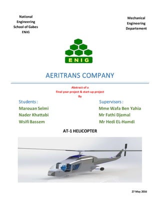
AT-1 HELICOPTER
27 May 2016
National
Engineering
School of Gabes
ENIG
Tunisia
Mechanical
Engineering
Departement
Subjects involved in thisprojectare:
Finite element methods, fluids mechanical, Computational fluid dynamic CFD, thermodynamics,
hydraulic systems, technical design, materials properties, project management,
SOLIDWORKS,ANSYS Workbench…
main parts :
Part1.CFD analysisof a rotor system fora helicopter:
Designof the rotor bladesbasedonNACA0012 airfoil
CFD simulationof a2 bladesrotorusingAnsysWorkbench
Part2.Studyanddesignof a transmission system for a helicopter:
Designof gearboxesandshaftsusingSolidWorks
Numerical analysisof gearboxes
Stressanalysisof gearboxesusingAnsysWorkbench
Part3.Design andanalysisof a helicopter fuselageandairframestructure:
Designof a helicopterfuselageandairframe structure usingSolidWorks
CFD analysisof a helicopterfuselage
Structural and modal analysisof a helicopterairframe
Current achievements in the project:
Part 1 . CFD analysis of a rotor systemfor a helicopter:
Design of the blades based on NACA0012 airfoils :
 Completed task
After carefulStudies the design of the helicopter blade was made based on the
NACA0012 airfoil, then using Momentum theory and Blade element theory the
blade shape was finally designed. The figure below shows thefinal CAD of the
blade.
CFD simulation of a teetering rotor using Ansys Workbench
 Completed task
Using Ansys Workbench softwaretheprevious design of blade was put under
severalsimulations to predict the interaction between the air flow and the blade
structureincluding : turbulence, velocity magnitude, pressure…
Some promising results was also withdrawn fromthe CFD simulations including:
Lift coefficient, drag coefficient, moment…
the figurebelow shows a sample of one of the simulations using Fluent tool in
Ansys Workbench.
Contours of pressure coefficient and history convergence of the CFD simulation
Part 2.Study and design of a transmissionsystem for a helicopter:
Design of gearboxes and shafts using SolidWorks:
 Completed task
After designing the fuselage, a design of the transmission systemwas the
second part of this project. The figures below shows theCAD model of
gearboxes and shafts using SolidWorks.
Numerical analysis of gearboxes:
 Completed task
The gearboxes and shafts was then numerically analyzed to make surethey resist
the torques and loads applied during several cases (hover, forward flight…). The
figures below shows thenumerical analysis process using MicrosoftExcel and
hand calculations.
Numerical analysis using Microsoft Excel
Stress analysis of gearboxes using Ansys Workbench:
 Completed task
Adding to the numerical analysis, the transmission components wentthrough
stress analysis to predict the possibledeformations. The stress analysis was made
using transient structuraltool in Ansys Workbench.Thefigurebelow shows the
results of the simulation.
Deformation of a bevel gear using transient structural tool in Ansys Workbench
Deformation of a gearboxes using transient structural tool in Ansys Workbench
Part3.Design andanalysisof a helicopter fuselageandairframestructure:
Design of a helicopter fuselage and airframe structure using
SolidWorks:
 Completed task
The idea was to design a robustand aerodynamic fuselage that can resist the
applied loads. The NASA ROBINfuselage was the basic startas it gives a great
reference in order to be able to comparethe results of the CFD simulations of
the desired fuselage with the ROBINfuselage results. You can see in the figure
below the preliminary shapeof the AT1 helicopter in compareto the ROBIN
fuselage.
ROBIN fuselage
AT1 fuselage
CFD analysis of a helicopter fuselage:
 Completed task
After designing the AT1 fuselage severalCFD simulations took place in order to
predict the air flow around the fuselagetherefore improving the aerodynamic
shapeif needed. The figure below shows oneof the CFD simulations process
frommeshing to results using Ansys Workbench.
Contours of turbulence using 𝐾 − 𝜀 model
in Fluent (Ansys Workbench)
After running the CFD simulations the shapeof the fuselage needed to be
improved in order to reduce turbulence and drag load. The figure below shows
the final shapewhich was validated later with further simulations.
Structural and modal analysis of a helicopter airframe:
 Completed task
After designing the fuselage, the airframeof the AT1 was designed based on the
shapeand dimensions of the fuselage. The airframe was then under several
simulations to predict it’s behaviors under static loads. Finally the airframewent
through modal analysis to withdraw the firstmodes that could cause resonance
under specific loads. The figures below shows the different states of both static
and modal analysis fromCAD to mesh to simulations.
Airframe design using SolidWorks
Static deformation of the airframe under loads using static structural tool in Ansys
Workbench
Modal analysis of the airframe using modal tool in Ansys Workbench
Current work in the project: (27 May 2016)
Currently it is the final step in the project which is the documentation and the
essay preparation of the project.

Contenu connexe

Tendances

Me2305 APPLIED HYDRAULICS AND PNEUMATICS
Me2305 APPLIED HYDRAULICS AND PNEUMATICSMe2305 APPLIED HYDRAULICS AND PNEUMATICS
Me2305 APPLIED HYDRAULICS AND PNEUMATICSBIBIN CHIDAMBARANATHAN
 
Drag Reduction of Front Wing of an F1 Car using Adjoint Optimisation
Drag Reduction of Front Wing of an F1 Car using Adjoint OptimisationDrag Reduction of Front Wing of an F1 Car using Adjoint Optimisation
Drag Reduction of Front Wing of an F1 Car using Adjoint Optimisationyasirmaliq
 
Fluid-Structure Interaction Over an Aircraft Wing
Fluid-Structure Interaction Over an Aircraft WingFluid-Structure Interaction Over an Aircraft Wing
Fluid-Structure Interaction Over an Aircraft WingIJERDJOURNAL
 
Design and Analysis of Solar Powered RC Aircraft
Design and Analysis of Solar Powered RC AircraftDesign and Analysis of Solar Powered RC Aircraft
Design and Analysis of Solar Powered RC Aircrafttheijes
 
Final fighter aircraft design adp 2
Final fighter aircraft design adp 2Final fighter aircraft design adp 2
Final fighter aircraft design adp 2Dudekula Jamal
 
Cfd in locomotive industory
Cfd in locomotive industoryCfd in locomotive industory
Cfd in locomotive industoryFarhat Asim
 
AC-G - Retaining Wall Plan and Section
AC-G - Retaining Wall Plan and SectionAC-G - Retaining Wall Plan and Section
AC-G - Retaining Wall Plan and SectionFidel Karim
 
SAE 2015 Final Report
SAE 2015 Final ReportSAE 2015 Final Report
SAE 2015 Final ReportAbhiram Doddi
 
A Study on how Spot Welds Affect the Stiffness of a Car Body T-joint
A Study on how Spot Welds Affect the Stiffness of a Car Body T-jointA Study on how Spot Welds Affect the Stiffness of a Car Body T-joint
A Study on how Spot Welds Affect the Stiffness of a Car Body T-jointsaeid ghaffari
 
Assessing the Aerodynamic Performance of a Formula SAE Model by means of CFD ...
Assessing the Aerodynamic Performance of a Formula SAE Model by means of CFD ...Assessing the Aerodynamic Performance of a Formula SAE Model by means of CFD ...
Assessing the Aerodynamic Performance of a Formula SAE Model by means of CFD ...saeid ghaffari
 
Double lane change maneuver (rigid vehicle model and non predictive driver mo...
Double lane change maneuver (rigid vehicle model and non predictive driver mo...Double lane change maneuver (rigid vehicle model and non predictive driver mo...
Double lane change maneuver (rigid vehicle model and non predictive driver mo...saeid ghaffari
 
Senior Design Presentation
Senior Design PresentationSenior Design Presentation
Senior Design PresentationMichael Davis
 

Tendances (20)

Me2305 APPLIED HYDRAULICS AND PNEUMATICS
Me2305 APPLIED HYDRAULICS AND PNEUMATICSMe2305 APPLIED HYDRAULICS AND PNEUMATICS
Me2305 APPLIED HYDRAULICS AND PNEUMATICS
 
Drag Reduction of Front Wing of an F1 Car using Adjoint Optimisation
Drag Reduction of Front Wing of an F1 Car using Adjoint OptimisationDrag Reduction of Front Wing of an F1 Car using Adjoint Optimisation
Drag Reduction of Front Wing of an F1 Car using Adjoint Optimisation
 
Fluid-Structure Interaction Over an Aircraft Wing
Fluid-Structure Interaction Over an Aircraft WingFluid-Structure Interaction Over an Aircraft Wing
Fluid-Structure Interaction Over an Aircraft Wing
 
TL project
TL projectTL project
TL project
 
Excerpts From JETT Revise
Excerpts From JETT ReviseExcerpts From JETT Revise
Excerpts From JETT Revise
 
Design and Analysis of Solar Powered RC Aircraft
Design and Analysis of Solar Powered RC AircraftDesign and Analysis of Solar Powered RC Aircraft
Design and Analysis of Solar Powered RC Aircraft
 
Final fighter aircraft design adp 2
Final fighter aircraft design adp 2Final fighter aircraft design adp 2
Final fighter aircraft design adp 2
 
Cfd in locomotive industory
Cfd in locomotive industoryCfd in locomotive industory
Cfd in locomotive industory
 
Index adp 2
Index adp 2Index adp 2
Index adp 2
 
Aero474 Design Example
Aero474 Design ExampleAero474 Design Example
Aero474 Design Example
 
AC-G - Retaining Wall Plan and Section
AC-G - Retaining Wall Plan and SectionAC-G - Retaining Wall Plan and Section
AC-G - Retaining Wall Plan and Section
 
Tutorial #5 - SACS Basic
Tutorial #5 - SACS BasicTutorial #5 - SACS Basic
Tutorial #5 - SACS Basic
 
SAE 2015 Final Report
SAE 2015 Final ReportSAE 2015 Final Report
SAE 2015 Final Report
 
A Study on how Spot Welds Affect the Stiffness of a Car Body T-joint
A Study on how Spot Welds Affect the Stiffness of a Car Body T-jointA Study on how Spot Welds Affect the Stiffness of a Car Body T-joint
A Study on how Spot Welds Affect the Stiffness of a Car Body T-joint
 
Assessing the Aerodynamic Performance of a Formula SAE Model by means of CFD ...
Assessing the Aerodynamic Performance of a Formula SAE Model by means of CFD ...Assessing the Aerodynamic Performance of a Formula SAE Model by means of CFD ...
Assessing the Aerodynamic Performance of a Formula SAE Model by means of CFD ...
 
SchlumbergerProjects
SchlumbergerProjectsSchlumbergerProjects
SchlumbergerProjects
 
Exam
ExamExam
Exam
 
Double lane change maneuver (rigid vehicle model and non predictive driver mo...
Double lane change maneuver (rigid vehicle model and non predictive driver mo...Double lane change maneuver (rigid vehicle model and non predictive driver mo...
Double lane change maneuver (rigid vehicle model and non predictive driver mo...
 
Senior Design Presentation
Senior Design PresentationSenior Design Presentation
Senior Design Presentation
 
Report-10th Dec,2015
Report-10th Dec,2015Report-10th Dec,2015
Report-10th Dec,2015
 

Similaire à abstract graduation project

KW_SOON_CAD_DESIGN_PORTFOLIO
KW_SOON_CAD_DESIGN_PORTFOLIOKW_SOON_CAD_DESIGN_PORTFOLIO
KW_SOON_CAD_DESIGN_PORTFOLIOKOK WEE SOON
 
CFD Analysis of conceptual Aircraft body
CFD Analysis of conceptual Aircraft bodyCFD Analysis of conceptual Aircraft body
CFD Analysis of conceptual Aircraft bodyIRJET Journal
 
IRJET-CFD Analysis of conceptual Aircraft body
IRJET-CFD Analysis of conceptual Aircraft bodyIRJET-CFD Analysis of conceptual Aircraft body
IRJET-CFD Analysis of conceptual Aircraft bodyIRJET Journal
 
CFD Simulation for Flow over Passenger Car Using Tail Plates for Aerodynamic ...
CFD Simulation for Flow over Passenger Car Using Tail Plates for Aerodynamic ...CFD Simulation for Flow over Passenger Car Using Tail Plates for Aerodynamic ...
CFD Simulation for Flow over Passenger Car Using Tail Plates for Aerodynamic ...IOSR Journals
 
A Review on Drag Reduction Methods of Ahmed Body at Different Rear Slant Angl...
A Review on Drag Reduction Methods of Ahmed Body at Different Rear Slant Angl...A Review on Drag Reduction Methods of Ahmed Body at Different Rear Slant Angl...
A Review on Drag Reduction Methods of Ahmed Body at Different Rear Slant Angl...IRJET Journal
 
Centrifugal Pump Analysis CFD case Study
Centrifugal Pump Analysis CFD case Study Centrifugal Pump Analysis CFD case Study
Centrifugal Pump Analysis CFD case Study CPDLR
 
COMPUTATIONAL FLUID DYNAMIC ANALYSIS OF NACA 0006 AEROFOIL AT DIFFERENT PARAM...
COMPUTATIONAL FLUID DYNAMIC ANALYSIS OF NACA 0006 AEROFOIL AT DIFFERENT PARAM...COMPUTATIONAL FLUID DYNAMIC ANALYSIS OF NACA 0006 AEROFOIL AT DIFFERENT PARAM...
COMPUTATIONAL FLUID DYNAMIC ANALYSIS OF NACA 0006 AEROFOIL AT DIFFERENT PARAM...IRJET Journal
 
SvenBlaserPortfolio
SvenBlaserPortfolioSvenBlaserPortfolio
SvenBlaserPortfolioSven Blaser
 
IRJET- Flow Simulation for Aircraft using Computational Fluid Dynamics
IRJET- Flow Simulation for Aircraft using Computational Fluid DynamicsIRJET- Flow Simulation for Aircraft using Computational Fluid Dynamics
IRJET- Flow Simulation for Aircraft using Computational Fluid DynamicsIRJET Journal
 
CFD Cornell Energy Workshop - M.F. Campuzano Ochoa
CFD Cornell Energy Workshop - M.F. Campuzano OchoaCFD Cornell Energy Workshop - M.F. Campuzano Ochoa
CFD Cornell Energy Workshop - M.F. Campuzano OchoaMario Felipe Campuzano Ochoa
 
CFD modelling calculation and simulation of bus
CFD modelling calculation and simulation of busCFD modelling calculation and simulation of bus
CFD modelling calculation and simulation of busIRJET Journal
 
AIRCRAFT PITCH EECE 682 Computer Control Of Dynamic.docx
AIRCRAFT PITCH EECE 682  Computer Control Of Dynamic.docxAIRCRAFT PITCH EECE 682  Computer Control Of Dynamic.docx
AIRCRAFT PITCH EECE 682 Computer Control Of Dynamic.docxgalerussel59292
 
DESIGN AND ANALYSIS OF HELICOPTER MAIN ROTOR HEAD
DESIGN AND ANALYSIS OF HELICOPTER MAIN ROTOR HEADDESIGN AND ANALYSIS OF HELICOPTER MAIN ROTOR HEAD
DESIGN AND ANALYSIS OF HELICOPTER MAIN ROTOR HEADIRJET Journal
 
Flow Anlaysis on Hal Tejas Aircraft using Computational Fluid Dynamics with D...
Flow Anlaysis on Hal Tejas Aircraft using Computational Fluid Dynamics with D...Flow Anlaysis on Hal Tejas Aircraft using Computational Fluid Dynamics with D...
Flow Anlaysis on Hal Tejas Aircraft using Computational Fluid Dynamics with D...IJAEMSJORNAL
 

Similaire à abstract graduation project (20)

KW_SOON_CAD_DESIGN_PORTFOLIO
KW_SOON_CAD_DESIGN_PORTFOLIOKW_SOON_CAD_DESIGN_PORTFOLIO
KW_SOON_CAD_DESIGN_PORTFOLIO
 
CFD Analysis of conceptual Aircraft body
CFD Analysis of conceptual Aircraft bodyCFD Analysis of conceptual Aircraft body
CFD Analysis of conceptual Aircraft body
 
IRJET-CFD Analysis of conceptual Aircraft body
IRJET-CFD Analysis of conceptual Aircraft bodyIRJET-CFD Analysis of conceptual Aircraft body
IRJET-CFD Analysis of conceptual Aircraft body
 
CFD Simulation for Flow over Passenger Car Using Tail Plates for Aerodynamic ...
CFD Simulation for Flow over Passenger Car Using Tail Plates for Aerodynamic ...CFD Simulation for Flow over Passenger Car Using Tail Plates for Aerodynamic ...
CFD Simulation for Flow over Passenger Car Using Tail Plates for Aerodynamic ...
 
Krishankant Sharma Portfolio
Krishankant Sharma PortfolioKrishankant Sharma Portfolio
Krishankant Sharma Portfolio
 
A Review on Drag Reduction Methods of Ahmed Body at Different Rear Slant Angl...
A Review on Drag Reduction Methods of Ahmed Body at Different Rear Slant Angl...A Review on Drag Reduction Methods of Ahmed Body at Different Rear Slant Angl...
A Review on Drag Reduction Methods of Ahmed Body at Different Rear Slant Angl...
 
Cad Port 2
Cad Port 2Cad Port 2
Cad Port 2
 
Centrifugal Pump Analysis CFD case Study
Centrifugal Pump Analysis CFD case Study Centrifugal Pump Analysis CFD case Study
Centrifugal Pump Analysis CFD case Study
 
COMPUTATIONAL FLUID DYNAMIC ANALYSIS OF NACA 0006 AEROFOIL AT DIFFERENT PARAM...
COMPUTATIONAL FLUID DYNAMIC ANALYSIS OF NACA 0006 AEROFOIL AT DIFFERENT PARAM...COMPUTATIONAL FLUID DYNAMIC ANALYSIS OF NACA 0006 AEROFOIL AT DIFFERENT PARAM...
COMPUTATIONAL FLUID DYNAMIC ANALYSIS OF NACA 0006 AEROFOIL AT DIFFERENT PARAM...
 
SvenBlaserPortfolio
SvenBlaserPortfolioSvenBlaserPortfolio
SvenBlaserPortfolio
 
IRJET- Flow Simulation for Aircraft using Computational Fluid Dynamics
IRJET- Flow Simulation for Aircraft using Computational Fluid DynamicsIRJET- Flow Simulation for Aircraft using Computational Fluid Dynamics
IRJET- Flow Simulation for Aircraft using Computational Fluid Dynamics
 
Aircraft Design
Aircraft DesignAircraft Design
Aircraft Design
 
CFD Cornell Energy Workshop - M.F. Campuzano Ochoa
CFD Cornell Energy Workshop - M.F. Campuzano OchoaCFD Cornell Energy Workshop - M.F. Campuzano Ochoa
CFD Cornell Energy Workshop - M.F. Campuzano Ochoa
 
Flow analysis
Flow analysisFlow analysis
Flow analysis
 
CFD modelling calculation and simulation of bus
CFD modelling calculation and simulation of busCFD modelling calculation and simulation of bus
CFD modelling calculation and simulation of bus
 
full report
full reportfull report
full report
 
AIRCRAFT PITCH EECE 682 Computer Control Of Dynamic.docx
AIRCRAFT PITCH EECE 682  Computer Control Of Dynamic.docxAIRCRAFT PITCH EECE 682  Computer Control Of Dynamic.docx
AIRCRAFT PITCH EECE 682 Computer Control Of Dynamic.docx
 
DESIGN AND ANALYSIS OF HELICOPTER MAIN ROTOR HEAD
DESIGN AND ANALYSIS OF HELICOPTER MAIN ROTOR HEADDESIGN AND ANALYSIS OF HELICOPTER MAIN ROTOR HEAD
DESIGN AND ANALYSIS OF HELICOPTER MAIN ROTOR HEAD
 
Flow Anlaysis on Hal Tejas Aircraft using Computational Fluid Dynamics with D...
Flow Anlaysis on Hal Tejas Aircraft using Computational Fluid Dynamics with D...Flow Anlaysis on Hal Tejas Aircraft using Computational Fluid Dynamics with D...
Flow Anlaysis on Hal Tejas Aircraft using Computational Fluid Dynamics with D...
 
Projects Portfolio
Projects PortfolioProjects Portfolio
Projects Portfolio
 

abstract graduation project

  • 1. AERITRANS COMPANY Abstract of a Final year project & start-up project By Students : Supervisors : Marouan Selmi Mme Wafa Ben Yahia Nader Khattabi Mr Fathi Djemal Wsifi Bassem Mr Hedi EL-Hamdi AT-1 HELICOPTER 27 May 2016 National Engineering School of Gabes ENIG Tunisia Mechanical Engineering Departement
  • 2. Subjects involved in thisprojectare: Finite element methods, fluids mechanical, Computational fluid dynamic CFD, thermodynamics, hydraulic systems, technical design, materials properties, project management, SOLIDWORKS,ANSYS Workbench… main parts : Part1.CFD analysisof a rotor system fora helicopter: Designof the rotor bladesbasedonNACA0012 airfoil CFD simulationof a2 bladesrotorusingAnsysWorkbench Part2.Studyanddesignof a transmission system for a helicopter: Designof gearboxesandshaftsusingSolidWorks Numerical analysisof gearboxes Stressanalysisof gearboxesusingAnsysWorkbench Part3.Design andanalysisof a helicopter fuselageandairframestructure: Designof a helicopterfuselageandairframe structure usingSolidWorks CFD analysisof a helicopterfuselage Structural and modal analysisof a helicopterairframe
  • 3. Current achievements in the project: Part 1 . CFD analysis of a rotor systemfor a helicopter: Design of the blades based on NACA0012 airfoils :  Completed task After carefulStudies the design of the helicopter blade was made based on the NACA0012 airfoil, then using Momentum theory and Blade element theory the blade shape was finally designed. The figure below shows thefinal CAD of the blade. CFD simulation of a teetering rotor using Ansys Workbench  Completed task Using Ansys Workbench softwaretheprevious design of blade was put under severalsimulations to predict the interaction between the air flow and the blade structureincluding : turbulence, velocity magnitude, pressure… Some promising results was also withdrawn fromthe CFD simulations including: Lift coefficient, drag coefficient, moment… the figurebelow shows a sample of one of the simulations using Fluent tool in Ansys Workbench.
  • 4. Contours of pressure coefficient and history convergence of the CFD simulation
  • 5. Part 2.Study and design of a transmissionsystem for a helicopter: Design of gearboxes and shafts using SolidWorks:  Completed task After designing the fuselage, a design of the transmission systemwas the second part of this project. The figures below shows theCAD model of gearboxes and shafts using SolidWorks. Numerical analysis of gearboxes:  Completed task The gearboxes and shafts was then numerically analyzed to make surethey resist the torques and loads applied during several cases (hover, forward flight…). The figures below shows thenumerical analysis process using MicrosoftExcel and hand calculations.
  • 6. Numerical analysis using Microsoft Excel Stress analysis of gearboxes using Ansys Workbench:  Completed task Adding to the numerical analysis, the transmission components wentthrough stress analysis to predict the possibledeformations. The stress analysis was made using transient structuraltool in Ansys Workbench.Thefigurebelow shows the results of the simulation. Deformation of a bevel gear using transient structural tool in Ansys Workbench
  • 7. Deformation of a gearboxes using transient structural tool in Ansys Workbench Part3.Design andanalysisof a helicopter fuselageandairframestructure: Design of a helicopter fuselage and airframe structure using SolidWorks:  Completed task The idea was to design a robustand aerodynamic fuselage that can resist the applied loads. The NASA ROBINfuselage was the basic startas it gives a great reference in order to be able to comparethe results of the CFD simulations of the desired fuselage with the ROBINfuselage results. You can see in the figure below the preliminary shapeof the AT1 helicopter in compareto the ROBIN fuselage. ROBIN fuselage AT1 fuselage
  • 8. CFD analysis of a helicopter fuselage:  Completed task After designing the AT1 fuselage severalCFD simulations took place in order to predict the air flow around the fuselagetherefore improving the aerodynamic shapeif needed. The figure below shows oneof the CFD simulations process frommeshing to results using Ansys Workbench.
  • 9. Contours of turbulence using 𝐾 − 𝜀 model in Fluent (Ansys Workbench) After running the CFD simulations the shapeof the fuselage needed to be improved in order to reduce turbulence and drag load. The figure below shows the final shapewhich was validated later with further simulations. Structural and modal analysis of a helicopter airframe:  Completed task After designing the fuselage, the airframeof the AT1 was designed based on the shapeand dimensions of the fuselage. The airframe was then under several simulations to predict it’s behaviors under static loads. Finally the airframewent through modal analysis to withdraw the firstmodes that could cause resonance
  • 10. under specific loads. The figures below shows the different states of both static and modal analysis fromCAD to mesh to simulations. Airframe design using SolidWorks Static deformation of the airframe under loads using static structural tool in Ansys Workbench
  • 11. Modal analysis of the airframe using modal tool in Ansys Workbench Current work in the project: (27 May 2016) Currently it is the final step in the project which is the documentation and the essay preparation of the project.