IEEE BASED ELECTRICAL PROJECTS 2012 ABSTRACT:SPEED CONTROL OF DC MOTOR USING RF&MOSFET
•Télécharger en tant que DOC, PDF•
3 j'aime•5,045 vues

PROJECTS DETAILS, thanks R.ASHOK KUMAR MAASTECH 89. RANGARAJAPURAM MAIN ROAD(NEAR SBI BANK) KODAMBAKKAM CHENNAI-600024 PH:044-24844676 ASHOK KUMAR-098402 34766 PL VISIT http://www.maastechindia.com

Recommandé
Contenu connexe
Plus de ASHOKKUMAR RAMAR
Plus de ASHOKKUMAR RAMAR (20)
Dernier
Dernier (20)
IEEE BASED ELECTRICAL PROJECTS 2012 ABSTRACT:SPEED CONTROL OF DC MOTOR USING RF&MOSFET
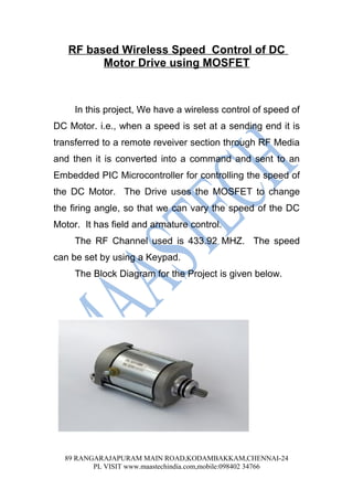
- 1. RF based Wireless Speed Control of DC Motor Drive using MOSFET In this project, We have a wireless control of speed of DC Motor. i.e., when a speed is set at a sending end it is transferred to a remote reveiver section through RF Media and then it is converted into a command and sent to an Embedded PIC Microcontroller for controlling the speed of the DC Motor. The Drive uses the MOSFET to change the firing angle, so that we can vary the speed of the DC Motor. It has field and armature control. The RF Channel used is 433.92 MHZ. The speed can be set by using a Keypad. The Block Diagram for the Project is given below. 89 RANGARAJAPURAM MAIN ROAD,KODAMBAKKAM,CHENNAI-24 PL VISIT www.maastechindia.com,mobile:098402 34766
- 2. Block Diagram (Transmitter section) Power PIC Microcontroller RF Supply Transmitter Rectifier and Filters KEYPAD LCD Display Line Voltage (230 VAC) 89 RANGARAJAPURAM MAIN ROAD,KODAMBAKKAM,CHENNAI-24 PL VISIT www.maastechindia.com,mobile:098402 34766
- 3. Block Diagram (Receiver Section) Line Voltgage Zero Bridge Crossing Ramp Rectifier Detector Generator DAC Err Comparator Buffer Ramp Volatage Feedback Comparator PIC Microcontroller Pulse Multiplier RF Recceiver Current Amlifier Line Volt 230 VAC Pulse Transformer MOSFE MOSFE T1 T2 Rectifier Using Diode Rectifier Using MOSFET Field DC Motor Armature 89 RANGARAJAPURAM MAIN ROAD,KODAMBAKKAM,CHENNAI-24 PL VISIT www.maastechindia.com,mobile:098402 34766
- 4. Drive Operation: The input Voltage is rectified and fed as a input to a ZCD for Ramp generator. Speed of the motor can be set through a remote RF Transmitter, which is acquired by a RF Receiver and then processed by the PIC Microcontroller, which further sends an output voltage using a DAC to the feedback comparator section. Both this ramp and the feedback voltage are compared and a pulse is generated for firing the MOSFET. Sometimes MOSFETs cannot be triggered by a single pulse. So we have a multiple pulse generator section using 555 timer IC. The output of the IC is fed for current amplification and given to a pulse transformer to isolate and produce simultaneous signals for firing two MOSFETS at a time. By controlling the firing angle of the MOSFET we can control the speed of the DC Motor. 89 RANGARAJAPURAM MAIN ROAD,KODAMBAKKAM,CHENNAI-24 PL VISIT www.maastechindia.com,mobile:098402 34766