SlideShare une entreprise Scribd logo
1  sur  106
Télécharger pour lire hors ligne
INDUSTRIAL MACHINES
Transformer
2
INTRODUCTION
• The transformer is one of the most useful electrical devices ever
invented.
• It can change the magnitude of alternating voltage or current from
one value to another.
• Transformers have no moving parts, rugged and durable in
construction.
• They also have a very high efficiency — about 99%.
• It essentially consists of two windings, the primary and secondary,
wound on a common laminated magnetic core.
• The winding connected to the a.c. source is called primary winding
and the one connected to load is called secondary winding.
Lecture Notes by Dr.R.M.Larik
3
INTRODUCTION (Contd.)
The alternating voltage V1 is applied to the primary.
The induced e.m.f. E2 in the secondary causes a secondary current I2.
Consequently, terminal voltage V2 will appear across the load.
Lecture Notes by Dr.R.M.Larik
4
WORKING PRINCIPLE
• When an alternating voltage V1 is applied to the primary, an
alternating flux Φ is set up in the core.
• The flux links both the windings and induces e.m.f.s E1 and E2 in them
according to Faraday’s laws of electromagnetic induction.
E1= − N1
dϕ
dt
and E2= − N2
dϕ
dt
E2
E1
=
N2
N1
• Number of turns of primary is N1 and that of secondary is N2.
• Magnitudes of E2 and E1 depend upon the number of turns on the
secondary and primary respectively.
Lecture Notes by Dr.R.M.Larik
5
WORKING PRINCIPLE (Contd.)
Points to note:
i) The transformer action is based on the laws of electromagnetic
induction.
ii) There is no electrical connection between the primary and
secondary.
iii) The a.c. power is transferred from primary to secondary through
magnetic flux.
iv) There is no change in frequency i.e., output power has the same
frequency as the input power.
v) The losses that occur in a transformer are:
a) core losses — eddy current and hysteresis losses
b) copper losses — due to resistance of windings
Lecture Notes by Dr.R.M.Larik
6
CONSTRUCTION OF A TRANSFORMER
i) The core is made of silicon steel having low hysteresis loss and
high permeability.
ii) Core is laminated and electrically separated by a thin coating of
insulating material in order to reduce eddy current loss and the no-
load current.
iii) Instead of placing primary on one limb and secondary on the other
one-half of each winding is wound on one limb to ensure tight
coupling between the two windings and reduce flux leakage.
iv) The winding resistances R1 and R2 are minimized to reduce I2R
loss, reduce winding temperature and to ensure high efficiency.
Types of Transformers
The manner in which the primary and secondary are wound on the
core, transformers are of two types (i) core-type and (ii) shell-type
Lecture Notes by Dr.R.M.Larik
7
CONSTRUCTION OF A TRANSFORMER (Contd.)
Core-type transformer
• In a core-type transformer, there is a
single path for the magnetic circuit.
• Half of the primary winding and half of
the secondary winding are placed
round each limb to reduce flux leakage.
Shell-type transformer
• Both the windings are placed round the
central limb to make double path for
magnetic circuit
• The other two limbs provide a low-
reluctance flux path.
Lecture Notes by Dr.R.M.Larik
8
CONSTRUCTION OF A TRANSFORMER (Contd.)
Windings
• The windings consist of the current-carrying insulated copper
conductors wound around the sections of the core.
• The windings are usually arranged concentrically around the core leg.
• Concentric coils are typically wound over cylinders with spacers
attached so as to form a duct between the conductors and the
cylinder.
• The flow of liquid through the windings is based on natural
convection, and is controlled by using the barriers placed within the
winding.
Lecture Notes by Dr.R.M.Larik
9
CONSTRUCTION OF A TRANSFORMER (Contd.)
Accessory Equipment
Liquid-Level Indicator
A liquid-level indicator is a standard feature on liquid-filled transformer
tanks, since the liquid medium is critical for cooling and insulation.
Pressure-Relief Devices
Pressure-relief devices are mounted on transformer tanks to relieve
excess internal pressures that might build up during operating conditions.
Liquid-Temperature Indicator
Liquid-temperature indicators measure the temperature of the internal
liquid.
Winding-Temperature Indicator
A winding-temperature simulation method is used to approximate the
hottest spot in the winding.
Lecture Notes by Dr.R.M.Larik
10
CONSTRUCTION OF A TRANSFORMER (Contd.)
Accessory Equipment (Contd.)
Sudden-Pressure Relay
A sudden- (or rapid-) pressure relay is intended to indicate a quick
increase in internal pressure that can occur when there is an internal fault
Desiccant (Dehydrating) Breathers
Desiccant breathers use a material such as silica gel to allow air to
enter and exit the tank, removing moisture as the air passes through.
Liquid-Preservation Systems
Liquid-temperature indicators measure the temperature of the internal
liquid
Lecture Notes by Dr.R.M.Larik
11
CONSTRUCTION OF A TRANSFORMER (Contd.)
Liquid-Preservation Systems
• Preservation systems isolates the
transformer’s internal environment
from the external environment.
• Conservator system involve the use
of a separate auxiliary tank.
• The auxiliary tank is allowed to
“breathe,” usually through a
dehydrating breather
Buchholz Relay
Its purpose is to detect faults that may occur in the transformer resulting
in generation of gases.
Lecture Notes by Dr.R.M.Larik
12
CONSTRUCTION OF A TRANSFORMER (Contd.)
Cooling of Transformers
Heat is produced in a transformer by the iron losses in the core and I2R
loss in the windings.
To prevent undue temperature rise, this heat is removed by cooling.
• In small transformers (< 50 kVA), natural air cooling is sufficient
• Medium size power or distribution transformers are cooled by
housing them in tanks filled with oil.
• For large transformers, external radiators are added to increase the
cooling surface of the oil filled tank.
• The oil circulates around the transformer and moves through the
radiators where the heat is released to surrounding air.
• Sometimes cooling fans blow air over the radiators to accelerate the
cooling process.
Lecture Notes by Dr.R.M.Larik
13
CONSTRUCTION OF A TRANSFORMER (Contd.)
Lecture Notes by Dr.R.M.Larik
14
IDEAL TRANSFORMER
• No winding resistance, no leakage flux and no iron losses in the cor
• When an alternating voltage V1 is applied to the primary, it draws a small
magnetizing current Im which lags behind the applied voltage by 90°.
• Im produces an alternating flux Φ which is proportional to and in phase with it
• The alternating flux Φ induces e.m.f. E1 in the primary and e.m.f. E2 in the
secondary.
• E1 is equal to and in opposition to V1 (Lenz’s law) and both E1 and E2 lag
behind flux Φ by 90°
Lecture Notes by Dr.R.M.Larik
15
E.M.F. EQUATION OF A TRANSFORMER
An alternating voltage V1 of frequency f is applied to the primary
The sinusoidal flux f produced by the primary can be represented as:
f= fm sin wt
The instantaneous e.m.f. e1 induced in the primary is:
e1 = – N1
dϕ
dt
= – N1
d
dt
(fm sin ωt)
= – ω N1fmcosωt = – 2p f N1fmcosωt
= 2p f N1fm sin (ωt – 90o) (i)
= Em1 sin(ωt - 90o)Em1 = 2 πfN1ϕm
It is clear from above equation that e.m.f. e1 induced in the primary
lags behind the flux f by 90°.
Lecture Notes by Dr.R.M.Larik
16
E.M.F. EQUATION OF A TRANSFORMER (Contd.)
Maximum value of induced e.m.f. in the primary is:
Em1= 2p f N1ϕm
The r.m.s. value E1 of the primary e.m.f. is
E1 =
Em1
2
=
2π f N1ϕm
2
or E1 = 4.44 f N1 ϕm = 4.44 f N1BmA
Similarly E2 = 4.44 f N2ϕm = 4.44 f N2BmA
where ϕm= Bm (flux density) x A (cross-sectional area of core)
In an ideal transformer, E1 = V1 and E2 =V2.
Lecture Notes by Dr.R.M.Larik
17
VOLTAGE TRANSFORMATION RATIO
From the induced e.m.f equations:
E2
E1
=
N2
N1
= K
The constant K is called voltage
transformation ratio.
For an Ideal Transformer
E1 = V1 and E2 = V2 as there is no voltage drop in the windings
E2
E1
=
V2
V1
=
N2
N1
= K
As there are no losses the volt-amperes input to the primary are equal
to the output volt-amperes
i.e. V1I1= V2I2 or
I2
I1
=
V1
V2
=
1
KLecture Notes by Dr.R.M.Larik
18
NUMERICAL PROBLEMS
Problem 1(a)
An ideal 25 kVA transformer has 500 turns on the primary and 40 turns on
the secondary winding. The primary is connected to 3000 V, 50 Hz
supply. Calculate (i) full-load primary and secondary currents (ii) the
secondary e.m.f. and (iii) the maximum core flux.
Solution:
Rating = 25 kVA, N1 = 500, N2 = 40, V1 = 3000 V, f = 50 Hz
I1 ?, I2 ?, E2?, Φm ?
Transformation ratio K =
N2
N1
=
40
500
= 0.08
i) Primary current I1 =
VA
V1
=
25 𝑥 103
3000
= 8.33 A
Lecture Notes by Dr.R.M.Larik
19
NUMERICAL PROBLEMS (Contd.)
Problem 1(a)
Solution(Contd.)
Secondary current I2 =
I1
K
=
8.33
0.08
= 104.2 A
ii)
E2
E1
= K
E2 = K x E1 = 0.08 x 3000 = 240 V
iii) E1 = 4.44 x f x N1 x Φm
3000 = 4.44 x 50 x 500 x Φm
Φm =
3000
4.44 x 50 x 500
= 27 x 10 -3Wb = 27 mWb
Lecture Notes by Dr.R.M.Larik
20
NUMERICAL PROBLEMS (Contd.)
Problem 1(b)
A single-phase transformer has 400 primary and 1000 secondary turns.
The net cross-sectional area of the core is 60 cm2. If the primary winding
be connected to a 50-Hz supply at 520 V, calculate (i) the peak value of
flux density in the core (ii) the voltage induced in the secondary winding.
Problem 1(c)
A single phase transformer has 500 turns in the primary and 1200 turns in
the secondary. The cross-sectional area of the core is 80 sq. cm. If the
primary winding is connected to a 50 Hz supply at 500 V, calculate (i)
Peak flux-density, and (ii) Voltage induced in the secondary.
Solution
N1 = 500, N2 = 1200, A = 80 cm2, V1 = 500 V, f = 50 Hz
Bm ?, V2 ?
Lecture Notes by Dr.R.M.Larik
21
NUMERICAL PROBLEMS (Contd.)
Problem 1(c)
Solution(Contd.)
E1= 4.44 x f x N1 x Φm
500 = 4.44 x 50 x 500 x Φm
Φm = 4.5x10⁻³Wb
i) Peak flux density Bm = Φm/A
=
4.5 x 10⁻³
80 x 10−4 = 0.5625 Wb/m2
ii)
V2
V1
=
N2
N1
V2 = V1 x
N2
N1
= 500 x
1200
500
= 1200 V
Lecture Notes by Dr.R.M.Larik
22
NUMERICAL PROBLEMS (Contd.)
Problem 1(d)
A 25 kVA, single-phase transformer has 250 turns on the primary and 40
turns on the secondary winding. The primary is connected to 1500 Volt,
50 Hz supply. Calculate (i) Primary and Secondary currents on full-load,
(ii) Secondary e.m.f., and (iii) maximum flux in the core.
Problem 2(a)
A single-phase 2200/250, 50 Hz transformer has a net core area of 36
cm2 and a maximum flux density of 6 Wb/m2. Calculate the number of
turns of primary and secondary.
Solution:
E1 = 2200 V, E2 = 250 V, f = 50 Hz, A = 36 cm2, Bm = 6 Wb/m2
N1 ?, N2 ?
Lecture Notes by Dr.R.M.Larik
23
NUMERICAL PROBLEMS (Contd.)
Problem 2(a)
Solution (Contd.):
Peak flux Φm = Bm (Wb/m2) x A (m2) = 6 x 36 x 10-4 = 0.0216 Wb
RMS primary induced e.m.f. E1 = 4.44 x f x N1 x Φm
N1 =
E1
4.44 x f x ∅m
=
2200
4.44 x 50 x 0.0216
= 459
N2 =
E2
4.44 x f x ∅m
=
250
4.44 x 50 x 0.0216
= 52
Problem 2(b)
A sinusoidal flux 0.02 Wb (max.) links with 55 turns of a transformer
secondary. Calculate the r.m.s. value of the induced e.m.f. in the
secondary. The supply frequency is 50 Hz.
Lecture Notes by Dr.R.M.Larik
24
WINDING POLARITY
Dot Convention
• It is not possible to tell the secondary
polarity of ideal transformer unless its
windings are physically examined.
• To overcome the problem dot convention
of transformer winding is used
• The dot appearing on end of the winding tells the polarity of voltage
and currents of secondary side.
• If the primary voltage is positive at the dotted end of the winding, then
the secondary voltage will be positive at the dotted end also.
• If the primary current of the transformer flows into the dotted end of the
primary, the secondary current will flow out of the dotted end of
secondary
• •
Lecture Notes by Dr.R.M.Larik
25
POWER IN IDEAL TRANSFORMER
The power supplied to the transformer by the primary circuit is given as:
Pin = V1 I1 cos Φ1
Φ1 is the angle between the primary voltage and primary current.
The power supplied by the transformer secondary circuit to its load is as:
Pout = V2 I2 cos Φ2
Φ2 is the angle between the secondary voltage and secondary current.
Since voltage and current angles are unaffected by an ideal transformer
Φ1 - Φ2 = 0
Primary and secondary windings of an ideal transformer have the same
power factor
Lecture Notes by Dr.R.M.Larik
26
POWER IN IDEAL TRANSFORMER (Contd.)
Comparison of Input and Output Power
The output power of a transformer is:
Pout = V2 I2 cos Φ
Applying the transformation ratio: V2 = V1 x K and I2 = I1 / K
Pout = (V1 x K) (I1 / K ) cos Φ
Pout = V1 I1 cos Φ = Pin
Thus, output power of an ideal transformer is equal to its input power.
The same relationship applies to reactive power and apparent power.
Lecture Notes by Dr.R.M.Larik
27
PRACTICAL TRANSFORMER
Iron Losses
• The iron losses depend upon the supply frequency, core volume
and maximum flux density in the core
• Magnitude of iron losses is quite small in a practical transformer.
Winding Resistances
When current flows through the windings, there will be power loss and
a loss in voltage due to IR drop, hence, E1 will be less than V1
whereas V2 will be less than E2.Lecture Notes by Dr.R.M.Larik
28
PRACTICAL TRANSFORMER (Contd.)
Leakage Reactances
• Primary current produces some flux Φ1 not linked with the secondary
winding
• Secondary current produces some flux Φ2 not linked with the primary
winding.
• The primary and secondary leakage flux Φ1 , Φ2 introduce inductive
reactances X1 and X2 in series with the primary and secondary windings
Lecture Notes by Dr.R.M.Larik
29
PRACTICAL TRANSFORMER (Contd.)
Transformer on No Load
• The primary will draw a small current I0 to supply the iron losses and
small amount of copper loss.
• Hence, primary no load current I0 is not 90° behind the applied
voltage V1 but lags it by an angle Φ0 < 90°
• The component IW, in phase with the applied voltage V1, is known as
active (working) or iron loss component and supplies the iron loss
and a small primary copper loss. IW = I0 cos Ф0Lecture Notes by Dr.R.M.Larik
30
PRACTICAL TRANSFORMER (Contd.)
Transformer on No Load (Contd.)
• The component Im lagging behind V1 by 90°, known as magnetizing
component, produces the mutual flux Φ in the core.
Im= I0 sin ϕ0
Clearly, I0 is phasor sum of Im and IW,
hence, Io = Im
2
+ IW
2
No load p,f, cosϕo =
IW
Io
• No load primary copper loss (i.e. I0
2 R1 ), being very small, may be
neglected, hence:
No load input power, W0 = Iron loss = V1 I0cosΦ0
• At no load, there is no secondary current so V2 = E2 and on the
primary side, the drops in R1 and X1are very small, hence V1 = E1.
Lecture Notes by Dr.R.M.Larik
31
PRACTICAL TRANSFORMER (Contd.)
Problem 3(a)
A 2200/200 V transformer draws a no-load primary current of 0.6 A,
and absorbs 400 watts. Find the magnetizing and iron loss currents.
Solution:
E1 = 2200, E2 = 200, Io = 0.6 A, No load input = 400 W
Iw ?, Im ?
Iron loss current Iw =
No load input (W)
Primary voltage
=
400
2200
= 0.182 A
Io
2 = Iw
2 + Im
2
Im = Io
2
− Iw
2
= (0.6)2 − (0.182)2 = 0.572 A
Lecture Notes by Dr.R.M.Larik
32
PRACTICAL TRANSFORMER (Contd.)
Problem 3(b)
A 2200/250 V transformer takes 0.5 A at a p.f. of 0.3 on open circuit.
Find magnetizing and working components of no-load primary current.
Problem 3(c)
A transformer takes a current of 0.6 A, and absorbs 64 W when
primary is connected to its normal supply of 200 V, 50 Hz; the
secondary being an open circuit. Find the magnetizing and iron loss
currents.
Solution:
Io = 0.6 A, Wo = 64 W, E1 = 200 V, f = 50 Hz
Iw ?, Im ?
No load primary power Wo = V1 Io Cos Φo
Iron loss current Iw = Io Cos Φo =
Wo
V1
Lecture Notes by Dr.R.M.Larik
33
PRACTICAL TRANSFORMER (Contd.)
Problem 3(c)
Solution (Contd.):
Iron loss current Iw =
64
200
= 0.32 A
Io
2 = Iw
2 + Im
2
Magnetizing current Im = Io
2
− Iw
2
= (0.6)2 − 0.32 2 = 0.507 A
Problem 3(d): A 230/2300 V transformer takes a no-load current of
6.5 A and absorbs 187 W. If the resistance of primary is 0.06  find (i)
the core loss (ii) no-load power factor (iii) active component of current
and (iv) magnetizing current.
Lecture Notes by Dr.R.M.Larik
34
LOADING OF TRANSFORMER
Ideal Transformer on Load
• The secondary e.m.f. E2 will
cause a current I2 to flow through
the load.
I2=
E2
ZL
=
V2
ZL
• In the case of inductive load the
current I2 lags behind V2 (or E2) by Φ2.
Lecture Notes by Dr.R.M.Larik
35
LOADING OF TRANSFORMER (Contd.)
Ideal Transformer on Load (Contd.)
• I2 sets up an m.m.f. N2 I2which produces a flux Φ2, in the opposite direction
to the main flux Φ (set up in the primary by the magnetizing current),
changing the main flux in the core and back e.m.f E1 tends to be reduced
• Momentarily the V1 gains upper hand over E1 and causes more current to
flow in the primary and the primary develops an m.m.f. which exactly
counterbalances the secondary m.m.f. N2 I2.
• The primary current I1 flows such that:
N1 I1 = N2 I2
I1 =
N2
N1
I2 = K I2
• Thus as the secondary current increases, the primary current I1(= K I2 ) also
increases to keep the mutual flux Φ constant.
• The power input automatically increases with increase in output.
Lecture Notes by Dr.R.M.Larik
36
LOADING OF TRANSFORMER (Contd.)
Ideal Transformer on Load (Contd.)
Phasor diagram:
• The value of K has been assumed unity so
that primary phasors are equal to secondary
phasors.
• Secondary current I2 lags behind V2 (or E2)
by Φ2 causing a primary current
I1 = K I2 = 1x I2 which is in anti-phase with it.
i) ϕ1 = ϕ2
or cos ϕ1 = cos ϕ2
ii) Since there are no losses in an ideal transformer, input primary
power is equal to the secondary output power i.e.,
V1I1 cosϕ1 = V2I2 cosϕ2
Lecture Notes by Dr.R.M.Larik
37
LOADING OF TRANSFORMER (Contd.)
Problem 4(a)
An ideal transformer having 90 turns on the primary and 2250 turns on
the secondary is connected to 200 V, 50 Hz supply. The load across the
secondary draws a current of 2 A at a p.f. of 0.8 lagging. Calculate
(i) the value of primary current and (ii) the peak value of flux linked with
the secondary. Draw the phasor diagram.
Solution:
N1 = 90, N2 = 2250, V2 = 200 V, f = 50 Hz,
I2= 2 A, Cos Φ2 = 0.8 lagging
I1 ?, Φm?
Transformation ratio K =
N2
N1
=
2250
90
= 25
i) Primary current I1 = K I2 = 25 x 2 = 50 A
Lecture Notes by Dr.R.M.Larik
38
LOADING OF TRANSFORMER (Contd.)
Problem 4(a)
Solution (Contd.):
ii) Primary induced voltage E1= 4.44 x f x N1 x Φm
Φm=
E1
4.44 x f x N1
=
200
4.44 x 50 x 90
= 0.01 Wb
Secondary induced voltage E2 = K x E1 = 25 x 200 = 5000 V
Secondary current phase angle Φ2 = Cos -1 0.8 = 36.9o
Lecture Notes by Dr.R.M.Larik
39
LOADING OF TRANSFORMER (Contd.)
Problem 4(b)
An ideal transformer has 1000 turns on its primary and 500 turns
on its secondary. The driving voltage on the primary side in 100 V
and the load resistance is 5 . Calculate V2, I1 and I2.
Lecture Notes by Dr.R.M.Larik
40
LOADING OF TRANSFORMER (Contd.)
Practical Transformer on Load
It is assumed that (i) transformer has no winding resistance and
leakage flux (ii) transformer has winding resistance and leakage flux.
No winding resistance and leakage flux
• With this assumption, V2 = E2 and V1 = E1,
• Take the case of inductive load causing the secondary current I2 to
lag the secondary voltage V2 by Φ2.
Lecture Notes by Dr.R.M.Larik
41
LOADING OF TRANSFORMER (Contd.)
Practical Transformer on Load (Contd.)
No winding resistance and leakage flux (Contd.)
The total primary current I1 must supply:
a) The no-load current I0 tomeet the iron losses in the transformer and
provides flux in the core.
b) A current I'2 to counteract the demagnetizing effect of secondary
current I2 andmagnitude of I'2 will be such that:
N1 I'2 = N2 I2
or I2
′
=
N2
N1
I2 = K I2
The total primary current I1 is the phasor sum of I'2 and I0 i.e.,
I1= I'2 +I0
where I'2 = - K I2
Current I'2 is 180° out of phase with I2.Lecture Notes by Dr.R.M.Larik
42
LOADING OF TRANSFORMER (Contd.)
Practical Transformer on Load (Contd.)
Phasor diagram
• Both E1 and E2 lag behind the mutual flux Φ
by 90°.
• The primary current I'2 neutralizes the
demagnetizing effect of secondary current I2.
• I'2 = K I2 and is anti-phase with I2.
• The phasor sum of I'2 and no load current I0
gives the total primary current I1.
• The value of K is assumed to be unity
Primary p.f. = cos Φ1
Secondary p.f. = cos Φ2
Primary input power = V1 I1 cos Φ1
Secondary output power = V2 I2 cos Φ2
Lecture Notes by Dr.R.M.Larik
43
LOADING OF TRANSFORMER (Contd.)
Practical Transformer on Load (Contd.)
Transformer with resistance and leakage reactance
• Due to voltage drop in R1 and X1 the primary e.m.f. E1 is less than V1.
• Due to voltage drop in R2 and X2 the secondary terminal voltage V2 is
less than the secondary e.m.f. E2.
Lecture Notes by Dr.R.M.Larik
44
LOADING OF TRANSFORMER (Contd.)
Practical Transformer on Load (Contd.)
Practical Transformer with resistance and leakage reactance (Contd.)
• The inductive load causes the secondary current I2 to lag behind the
secondary voltage V2 by ϕ2.
• The total primary current I1 must meet two requirements:
a) Supply the no-load current I0 to meet the iron losses in the
transformer and to provide flux in the core.
b) Supply a current I'2 to counteract the demagnetizing effect of
secondary current I2.
• The magnitude of I'2 will be such that:
N1 I'2 = N2 I2
I2
′
=
N2
N1
I2 = K I2
Lecture Notes by Dr.R.M.Larik
45
LOADING OF TRANSFORMER (Contd.)
Practical Transformer with resistance and leakage reactance (Contd.)
The total primary current I1 will be the phasor sum of I'2 and I0
I1 = I'2 + I0 where I'2 = - K I2
V1 = - E1 + I1 (R1 + jX1) where I1 = I0 + (- K I2)
= - E1 + I1 Z1
V2 = E2 - I2 (R2 + jX2)
= E2 - I2 Z2
Phasor diagram.
• Both E1 and E2 lag the mutual flux ϕ by 90°.
• The primary current I'2 neutralizes the demagnetizing effect of secondary
current I2.
• I'2 = K I2 and is opposite to I2.
• The phasor sum of I'2 and no load current I0 is the total primary current I1
Lecture Notes by Dr.R.M.Larik
46
LOADING OF TRANSFORMER (Contd.)
Practical Transformer on Load (Contd.)
Phasor diagram (Contd.)
• Back e.m.f. E1 opposes the applied voltage V1
• If I1 R1 (in phase with I1) and I1 X1 (90° ahead of
I1) is added to - E1, we get the applied primary
voltage V1.
• The phasor E2 represents the induced e.m.f. in
the secondary by the mutual flux Φ.
• The secondary terminal voltage V2 is shown after
subtracting I2 R2 and I2 X2 from E2.
Load power factor = cos ϕ2
Primary power factor = cos ϕ1
Input power to transformer, P1 = V1 I1 cos ϕ1
Output power of transformer, P2 = V2 I2 cos ϕ2
Lecture Notes by Dr.R.M.Larik
47
LOADING OF TRANSFORMER (Contd.)
Problem 5(a)
A single-phase transformer with a ratio of 440/110 V takes a no-load
current of 5A at 0.2 power factor lagging. If the secondary supplies a
current of 120 A at a p.f. of 0.8 lagging, estimate the current taken by the
primary.
Solution:
V1= 440 V, V2 = 110 V, Io = 5 A, Cos Φo = 0.2, I2 = 120 A, Cos Φ2 = 0.8 lag
I1 ?,
Transformation ratio K =
V2
V1
=
110
440
= 0.25
I2
′
=K x I2 = 0.25 x 120 = 30 A
Φ2 = Cos-1 0.8 = 36.87o
Φo = Cos-1 0.2 = 78.46o
Angle between I2
′
and Io = 78.46o − 36.87o = 41.59o
Lecture Notes by Dr.R.M.Larik
48
LOADING OF TRANSFORMER (Contd.)
Problem 5(a)
Solution(Contd.): I1 = Io
2
+ I2
′ 2 + 2 Io I2
′
Cos 41.59o
= 5 2 + 30 2 + 2 x 5 x 30 x Cos 41.59o = 33.9 A
Lecture Notes by Dr.R.M.Larik
49
LOADING OF TRANSFORMER (Contd.)
Problem 5(b)
A single-phase transformer has 1000 turns on the primary and 200 turns
on the secondary. The no load current is 3 amp. at a p.f. of 0.2 lagging.
Calculate the primary current and power-factor when the secondary
current is 280 amp. at a p.f. of 0.80 lagging.
Lecture Notes by Dr.R.M.Larik
50
IMPEDANCE RATIO OF TRANSFORMER
Z2=
V2
I2
Z1 =
V1
I1
Z2
Z1
=
V2
V1
x
I1
I2
Z2
Z1
= K2
Impedance ratio (Z2/Z1) is equal to the square of voltage
transformation ratio.
Similarly,
R2
R1
= K2 and
X2
X1
= K2
Consider a transformer having impedance Z2 in the secondary.
Lecture Notes by Dr.R.M.Larik
51
SHIFTING IMPEDANCES IN A TRANSFORMER
The resistance and reactance of one winding can be transferred to
the other to make the analysis of the transformer simple.
When secondary resistance / reactance is transferred to primary,
called equivalent secondary resistance / reactance referred to primary
and is denoted by R'2 or X'2, it is divided by K2.
Referred to primary
Lecture Notes by Dr.R.M.Larik
52
SHIFTING IMPEDANCES IN A TRANSFORMER (Contd.)
Referred to secondary
When primary resistance / reactance is transferred to secondary,
called equivalent primary resistance / reactance referred to the
secondary and is denoted by R'1 or X'1, it is multiplied by K2.
Lecture Notes by Dr.R.M.Larik
53
SHIFTING IMPEDANCES IN A TRANSFORMER (Contd.)
Problem 6(a)
A 30 kVA, 2400/120 V, 50 Hz transformer has a high voltage winding
resistance of 0.1  and a leakage reactance of 0.22 . The low voltage
winding resistance is 0.035  and the leakage reactance is 0.012 .
Find the equivalent winding resistance, reactance and impedance
referred to the (i)high voltage side and (ii)the low-voltage side.
Solution:
Trafo rating = 30 kVA, V1 = 2400 V, V2 = 120 V, R1 = 0.1 , X1 = 0.22 ,
R2= 0.035 , X2 = 0.01 
R01 ?, X01 ?, Z01 ?, R02 ?, X02 ?, Z02 ?
Transformation ratio K =
V2
V1
=
120
2400
= 0.05
R01 = R1 + R2
′
= R1 +
R2
K2 = 0.1 +
0.035
0.052 = 14.1 Ω
Lecture Notes by Dr.R.M.Larik
54
SHIFTING IMPEDANCES IN A TRANSFORMER (Contd.)
Problem 6(a)
Solution (Contd.):
X01 = X1 + X2
′
= X1 +
X2
K2 = 0.22 +
0.012
0.052 = 5.02 Ω
Z01= R01
2 + X01
2 = 14.1 2 + 5.02 2 = 15 Ω
R02= R2 + R1
′
= R2 + K2 x R1 = 0.035 + (0.05)2 x 0.1 = 0.03525 Ω
X02 = X2 + X1
′
= X2 + K2 x X1 = 0.012 + (0.05)2 x 0.22 = 0.01255 Ω
Z02 = R02
2 + X02
2 = 0.03525 2 + 0.01255 2 = 0.0374 Ω
Problem 6(b)
A 10 kVA, 2000/400 v single-phase transformer has R1 = 5 ; X1 = 12
; R2= 0.2  and X2 = 0.48 . Determine the equivalent impedance of
the transformer referred to (i) primary side (ii) secondary side.
Lecture Notes by Dr.R.M.Larik
55
SHIFTING IMPEDANCES IN A TRANSFORMER (Contd.)
Problem 6(c)
A 100 kVA, 1100/220 V, 50 Hz, single-phase transformer has a
leakage impedance of (0.1 +J 0.40) ohm for the H.V. winding and
(0.006 +J 0.015) ohm for the L.V. winding. Find the equivalent winding
resistance, reactance and impedance referred to the H.V. and L.V.
sides.
Problem 7(a)
A 50 kVA, 4,400/220 V transformer has R1 = 3.45 , R2 = 0.009 .
The values of reactances are X1 = 5.2  and X2 = 0.015 . Calculate
for the transformer (i) equivalent resistance as referred to primary (ii)
equivalent resistance as referred to secondary (iii) equivalent
reactance as referred to both primary and secondary (iv) equivalent
impedance as referred to both primary and secondary (v) total Cu
loss, first using individual resistances of the two windings and
secondly, using equivalent resistances as referred to each side.
Lecture Notes by Dr.R.M.Larik
56
SHIFTING IMPEDANCES IN A TRANSFORMER (Contd.)
Problem 7(a)
Solution (Contd.):
Trafo rating = 50 kVA, V1 = 4400 V, V2 = 220 V, R1 = 3.45 ,
X1= 5.21 , R2= 0.009 , X2 = 0.015 
R01 ?, X01 ?, Z01 ?, R02 ?, X02 ?, Z02 ? Copper loss using i) individual
resistances of primary and secondary and using ii) equivalent
resistances ?
Transformation ratio K =
V2
V1
=
220
4400
= 0.05
I1 =
VA
V1
=
50000
4400
= 11.36 A
I2=
VA
V2
=
50000
220
= 227 A
R01 = R1 + R2
′
= R1 +
R2
K2 = 3.45 +
0.009
(0.05)2 = 7.05 Ω
Lecture Notes by Dr.R.M.Larik
57
SHIFTING IMPEDANCES IN A TRANSFORMER (Contd.)
Problem 7(a)
Solution (Contd.):
X01= X1 + X2
′
= X1 +
X2
K2 = 5.2 +
0.015
(0.05)2 = 11.2 Ω
Z01 = 𝑅01
2 + 𝑋01
2 = 7.05 2 + 11.2 2 = 13.23 Ω
R02 = R2 + R1
′
= R2 + K2 x R1 = 0.009 + (0.05)2 x 3.45 = 0.0176 Ω
X02 = X2 + X1
′
= X2 + K2 x X1 = 0.015 + (0.05)2 x 5.2 = 0.028 Ω
Z02 = 𝑅02
2 + 𝑋02
2 = 0.0176 2 + 0.028 2 = 0.033 Ω
Total copper loss = I1
2
x R1+ I2
2
x R2 = (11.36)2 x 3.45
= (227)2 x 0.009 = 910 W
Also Cu loss = I1
2
x R01 = (11.36)2 x 7.05 = 910 W
= I2
2
x R02 = (227)2 x 0.0176 = 910 W
Lecture Notes by Dr.R.M.Larik
58
SHIFTING IMPEDANCES IN A TRANSFORMER (Contd.)
Problem 7(b)
A 100 kVA , 2200/440 V transformer has R1 = 0.3 ; X1 = 1.1  ;
R2 = 0.01  and X2 = 0.035 . Calculate (i) the equivalent impedance
of the transformer referred to primary and (ii) total copper losses.
Lecture Notes by Dr.R.M.Larik
59
EQUIVALENT CIRCUIT OF TRANSFORMER
• The parallel circuit R0 - X0 is no-load equivalent circuit.
• The resistance R0 represents the core losses supplied by the current IW.
• The inductive reactance X0 represents a loss-free coil which passes the
magnetizing current Im.
• The phasor sum of IW and Im is the no-load current I0 of the transformer.
Lecture Notes by Dr.R.M.Larik
60
EQUIVALENT CIRCUIT OF TRANSFORMER (Contd.)
• Equivalent circuit has created two circuits separated by an ideal
transformer whose function is to change values according to the
equation:
E2
E1
=
N2
N1
=
I2
′
I2
• When the transformer is on no-load, there is no current in the secondary
winding, however, the primary draws a small no-load current I0.
• When load ZL is connected to the secondary circuit the voltage E2 induced
in the secondary by mutual flux will produce a secondary current I2.
V2 = E2 - I2 (R2 + j X2 ) = E2 - I2 Z2
Lecture Notes by Dr.R.M.Larik
61
EQUIVALENT CIRCUIT OF TRANSFORMER (Contd.)
• When the transformer is loaded to carry the secondary current I2, the
primary current consists of no-load current I0 to provide
• Since the transformer is ideal, the primary induced voltage E1 can be
calculated from the relation:
E1
E2
=
N1
N2
• If we add I1R1 and I1X1 drops to E1, we get the primary input voltage V1
V1 = - E1 + I1 (R1 + j X1) = - E1 + I1 Z1
– magnetizing current,
– the current required to supply the core losses
– primary current I'2 (= K I2) required to supply the load on the
secondary.
Lecture Notes by Dr.R.M.Larik
62
SIMPLIFIED EQUIVALENT CIRCUIT OF A LOADED TRANSFORMER
• The no-load current I0 is small as compared to the rated primary
current, hence, voltage drops in R1 and X1 due to I0 can be neglected.
• The equivalent circuit can be simplified by transferring the shunt circuit
R0 - X0 to the input terminals.
Lecture Notes by Dr.R.M.Larik
63
SIMPLIFIED EQUIVALENT CIRCUIT OF A LOADED TRANSFORMER
Equivalent circuit referred to primary
If all the secondary quantities are referred to the primary, we get the
equivalent circuit of the transformer referred to the primary
Lecture Notes by Dr.R.M.Larik
64
SIMPLIFIED EQUIVALENT CIRCUIT OF A LOADED TRANSFORMER
Equivalent circuit referred to primary (Contd.)
When secondary quantities are referred to primary, impedances are
divided by K2, voltages are divided by K and currents are multiplied by K.
R2
′
=
R2
K2 ; X2
′
=
X2
K2 ; ZL
′
=
ZL
K2 ; V2
′
=
V2
K
; I2
′
= K I2 ; Z01= R01 + j X01
where R01 = R1 + R'2 ; X01 = X1 + X'2
The equivalent circuit of the transformer can be further reduced
Lecture Notes by Dr.R.M.Larik
65
SIMPLIFIED EQUIVALENT CIRCUIT OF A LOADED TRANSFORMER
Equivalent circuit referred to primary (Contd.)
Phasor diagram
• The referred value of load voltage
V'2 is chosen as the reference.
• The referred value of load current
I'2 is shown lagging V'2 by angle Φ2.
• For a given value of V'2 both I'2 and
Φ2 are determined by the load.
• The voltage drop I'2 R01 is in phase with I'2 and the voltage drop I'2 X01,
leads I'2 by 90°.
Lecture Notes by Dr.R.M.Larik
66
SIMPLIFIED EQUIVALENT CIRCUIT OF A LOADED TRANSFORMER
Equivalent circuit referred to secondary
If all the primary quantities are referred to secondary, we get the
equivalent circuit of the transformer referred to secondary
Lecture Notes by Dr.R.M.Larik
67
SIMPLIFIED EQUIVALENT CIRCUIT OF A LOADED TRANSFORMER
Equivalent circuit referred to secondary (Contd.)
When primary quantities are referred to secondary impedances are
multiplied by K2, voltages are multiplied by K and currents are divided by K
R'1 = K2 R1 ; X'1 = K2 X1 ; V'2 = K V1 ; I'1 = I1/K
Z02 = R02 + j X02
where R02 = R2 + R'1 ; X02 = X2 + X'1
The equivalent circuit of the transformer can be further reduced
Lecture Notes by Dr.R.M.Larik
68
SIMPLIFIED EQUIVALENT CIRCUIT OF A LOADED TRANSFORMER
Equivalent circuit referred to secondary (Contd.)
Phasor diagram
• The load voltage V2 is chosen
as reference.
• The load current I2 is shown
lagging the load voltage V2 by
angle ϕ2.
• The voltage drop I2 R02 is in
phase with I2 and the voltage
drop I2 X02 leads I2 by 90°.
• Current I'W is in phase with V'1 & the current I'm lags behind V'1 by 90°
• The sum of I'W and I'm gives the referred value of no-load current I'0.
• The sum of I'0 and I2 gives the referred primary current I'1 (= I1/K).
Lecture Notes by Dr.R.M.Larik
69
SIMPLIFIED EQUIVALENT CIRCUIT OF A LOADED TRANSFORMER
Problem 8(a):
A 10 kVA, 2000/400 V single-phase transformer has the following data:
R1 = 5 ; X1 = 12 ; R2 = 0.2 ; X2 = 0.48 
Determine the secondary terminal voltage at full load, 0.8 p.f. lagging
when the primary supply voltage is 2000 V.
Solution:
Trafo rating = 10 kVA, V1 = 2000 V, V2 = 400 V, R1 = 5 , X1 = 12 ,
R2= 0.2 , X2 = 0.48 , P.f. = 0.8
Secondary terminal voltage at full load V2 ?
Transformation ratio K =
V2
V1
=
400
2000
= 0.2
R02 = R2 + R1
′
= R2 + K2 x R1 = 0.2 + (0.2)2 x 5 = 0.4 Ω
X02 = X2 + X1
′
= X2 + K2 x X1 = 0.48 + (0.2)2 x 12 = 0.96 Ω
Lecture Notes by Dr.R.M.Larik
70
SIMPLIFIED EQUIVALENT CIRCUIT OF A LOADED TRANSFORMER
Problem 8(a):
Solution (Contd.):
Full load secondary current I2 =
VA
V2
=
10000
400
= 25 A
Φ2 = Cos -1 0.8 = 36.9o, Sin Φ2 = Sin 36.9o = 0.6
Approximate voltage drop = I2 (R02 Cos Φ2 + X02 Sin Φ2)
= 25 (0.4 x 0.8 + 0.96 x 0.6) = 22.4 V
Secondary terminal voltage at full load
V2 = 400 – 22.4 = 377.6 V
Problem 8(b):
A 230/460 V transformer has a primary resistance of 0.2  and
reactance of 0.5  and the corresponding values for the secondary are
0.75  and 1.8  respectively. Find the secondary terminal voltage
when supplying 10 A at 0.8 p.f. lagging.Lecture Notes by Dr.R.M.Larik
71
VOLTAGE REGULATION
The voltage regulation of a transformer is the arithmetic difference
between the no-load secondary voltage (0V2) and the secondary
voltage V2 on load expressed as percentage of no-load voltage i.e.
%age voltage regulation =
0V2 − V2
0V2
x 100
0V2- V2= I2 R02cosϕ2± I2 X02sin ϕ2
The +ve sign is for lagging p.f. and -ve sign for leading p.f.
Percentage voltage regulation of the transformer will be the same
whether primary or secondary side is considered.
Lecture Notes by Dr.R.M.Larik
72
VOLTAGE REGULATION
Problem 8(c):
The primary and secondary windings of a 40 kVA, 6600/250 V single-
phase transformer has resistance of 10  and 0.02  respectively. The
leakage reactance of the transformer referred to primary side is 35 .
Calculate percentage voltage regulation of the transformer when
applying full-load current at p.f. 0.8 lagging.
Solution:
Trafo rating = 40 kVA, V1 = 6600 V, V2 = 230 V, R1 = 10 , X01 = 35 ,
R2 = 0.02 , Cos Φ2 = 0.8
Percentage voltage regulation at full load and 0.8 p.f. ?
Transformation ratio K =
V2
V1
=
230
6600
= 0.03788
R01 = R1 + R2
′
= R1 +
R2
K2 = 10 +
0.02
(0.03788)2 = 23.932 Ω
Lecture Notes by Dr.R.M.Larik
73
VOLTAGE REGULATION
Problem 8(c):
Solution (Contd.):
X01= 35 
Full load primary current
I1 =
40000
6600
= 6.06 A
Φ2 = Cos -1 0.8 = 36.9o, Sin Φ2 = Sin 36.9o = 0.6
Approximate voltage drop = I1 (R01 Cos Φ2 + X01 Sin Φ2)
= 6.06 (23.93 x 0.8 + 3.5 x 0.6) = 243 V
Percentage voltage regulation
=
243 x 100
6600
= 3.7 %
Lecture Notes by Dr.R.M.Larik
74
TRANSFORMER TESTS
Open-Circuit or No-Load Test
• The rated voltage is applied to the low-voltage (primary) winding while
the high voltage side is left open-circuited.
• The applied primary voltage V1 is measured by the voltmeter, the no
load current I0 by ammeter and no-load input power W0 by wattmeter.
• As the normal rated voltage is applied to the primary, the normal iron
losses will occur in the transformer core.
• Wattmeter will record the iron losses and small copper loss in the
primary.
• Since no-load current I0 is very small the Cu losses in the primary
under no-load condition are negligible as compared with iron losses.
• Wattmeter reading practically gives the iron losses in the transformer.
Lecture Notes by Dr.R.M.Larik
75
TRANSFORMER TESTS (Contd.)
Open-Circuit or No-Load Test
Iron losses, Pi = Wattmeter reading = W0
No load current = Ammeter reading = I0
Applied voltage = Voltmeter reading = V1
Input power, W0 = V1 I0 cos Φ0
Equivalent circuit
Lecture Notes by Dr.R.M.Larik
76
TRANSFORMER TESTS (Contd.)
Open-Circuit or No-Load Test (Contd.)
Input power, W0 = V1 I0cosϕ0
No load p.f., cosϕo =
Wo
V1
Io
IW = Iocosϕo; Im = Io sin ϕo
Ro =
V1
IW
and Xo =
V1
Im
Thus open-circuit test enables us to determine iron losses and parameters
R0 and X0 of the transformer
Lecture Notes by Dr.R.M.Larik
77
TRANSFORMER TESTS (Contd.)
Short-Circuit or Impedance Test
• The test is conducted to determine R01 (or R02), X01 (or X02) and full-
load copper losses of the transformer.
• In the test, the secondary (usually low-voltage winding) is short-
circuited by a thick conductor and variable low voltage is applied to
the primary
Equivalent circuit
Lecture Notes by Dr.R.M.Larik
78
TRANSFORMER TESTS (Contd.)
Short-Circuit or Impedance Test (Contd.)
• The input voltage is gradually raised till full-load current I1 flows in the
primary then I2 in the secondary also has full-load value since I1/I2 =
N2/N1
• Under this condition, the copper loss in the windings is the same as
that on full load.
• There is no output from the transformer under short-circuit conditions,
hence, input power is all loss and this loss is almost entirely copper
loss as iron loss in the core is negligibly small since the voltage VSC is
very small.
• The wattmeter will practically register the full-load copper losses in the
transformer windings.
• The equivalent circuit of a transformer on short circuit has been
referred to primary; the no-load current negligibly small.Lecture Notes by Dr.R.M.Larik
79
TRANSFORMER TESTS (Contd.)
Short-Circuit or Impedance Test (Contd.)
Full load Cu loss PC (Wattmeter reading) = WS
Applied voltage (Voltmeter reading) = VSC
F.L. primary current (Ammeter reading) = I1
PC= I1
2
R1 + I1
2
R2
′
= I1
2
R01
R01=
PC
I1
2
where R01 is the total resistance of transformer referred to primary.
Total impedance referred to primary, Z01 =
VSC
I1
Total leakage reactance referred to primary, X01= Z01
2
− R01
2
Short-circuit p.f, cos ϕ2 =
PC
VSC I1
Thus short-circuit test gives full-load Cu loss, R01 and X01.
Lecture Notes by Dr.R.M.Larik
80
TRANSFORMER LOSSES
Core or Iron losses
• The core or iron losses consist of hysteresis and eddy current losses
and occur in the transformer core due to the alternating flux.
• These can be determined by open-circuit test.
• Iron or Core losses, Pi = Hysteresis loss + Eddy current loss =
Constant losses
• The hysteresis loss can be minimized by using steel of high silicon
content
• The eddy current loss can be reduced by using core of thin
laminations.
Lecture Notes by Dr.R.M.Larik
81
TRANSFORMER LOSSES (Contd.)
Copper Losses
• These losses occur in both the primary and secondary windings
due to their resistance.
• The losses can be determined by short-circuit test.
Total Cu losses, PC = I1
2 R1 + I2
2 R2
= I1
2 R01 or I2
2 R02
• Copper losses vary as the square of load current, thus, if copper
losses are 400 W at a load current of 10 A, they will be (1/2)2 x
400 = 100 W at a load current of 5A.
• Total losses in a transformer = Pi + PC = Constant losses +
Variable losses
• In a transformer, copper losses are about 90% of the total losses.
Lecture Notes by Dr.R.M.Larik
82
EFFECIENCY OF TRANSFORMER
• Efficiency of a transformer is defined as:
Efficiency =
Output power
Input power
=
Output power
Output power +Losses
• Efficiency can be determined by directly loading the transformer and
measuring the input power and output power, however, such method has the
following drawbacks:
– Since the efficiency of a transformer is very high, even 1% error in each
wattmeter (output and input) may give ridiculous results and the test may
give efficiency even higher than 100%.
– While performing test of transformer on load, considerable amount of
power is wasted.
– It is generally difficult to have a device that can absorb all the output power.
– The test gives no information about the proportion of various losses.
• In practice, open-circuit and short-circuit tests are carried out to find the
efficiency.
Lecture Notes by Dr.R.M.Larik
83
EFFECIENCY OF TRANSFORMER (Contd.)
Efficiency from Transformer Tests
F.L. Iron loss = Pi... from open-circuit test
F.L. Cu loss = PC... from short-circuit test
Total F.L. losses = Pi + PC
We can now find the full-load efficiency of the transformer at any p.f.
without actually loading the transformer.
F.L. efficiency, ηF.L. =
Full−load VA x p.f.
Full−load VA x p.f. + Pi+ PC
Also for any load equal to x x full-load,
Corresponding total losses = Pi + x2 PC
Corresponding ηx. =
xx Full−load VA x p.f.
xx Full−load VA x p.f. + Pi+ 𝑥2PC
This slide needs correction
Lecture Notes by Dr.R.M.Larik
84
EFFECIENCY OF TRANSFORMER (Contd.)
Problem 9(a):
In no-load test of single-phase transformer, the following test data were
obtained:
Primary voltage : 220 V ; Secondary voltage : 110 V;
Primary current : 0.5 A ; Power input : 30 W.
Find (i) the magnetising component of no-load current (ii) its working (or
loss) component (iii) the iron loss. Resistance of the primary winding =
0.6 ohm.
Solution:
V1 = 220 V, V2 = 110 V, Io = 0.5 A, Wo = 30 W, R1 = 0.6 
Im ?, IW ?, Copper loss PC ?, Iron loss Pi ?
Transformation ratio K =
V2
V1
=
110
220
= 0.5
Wo = V1 Io Cos Φo Lecture Notes by Dr.R.M.Larik
85
EFFECIENCY OF TRANSFORMER (Contd.)
Problem 9(a):
Solution (Contd.):
Cos Φo =
Wo
V1Io
=
30
220 x 0.5
= 0.273
Φo = Cos-1 0.273 = 74.16o, Sin Φo = Sin 74.16o = 0.962
Iw = Io Cos Φo = 0.5 x 0.273 = 0.1365 A
Im = Io Sin Φo = 0.5 x 0.962 = 0.48 A
Copper loss PC = Io
2
R1 = (0.5)2 x 0.6 = 0.15 W
Iron loss Pi = 30 – 0.15 = 29.85 W
Problem 9(b): Obtain the equivalent circuit of a 200/400 V, 50 Hz, 1-
phase transformer from the following test data :
O.C test : 200 V, 0.7 A, 70 W – on L.V. side
S.C. test : 15 V, 10 A, 85 W – on H.V. side
Calculate the secondary voltage when delivering 5 kW at 0.8 p.f.
lagging, the primary voltage being 200V.Lecture Notes by Dr.R.M.Larik
86
AUTOTRANSFORMER
• Autotransformer has a single winding and a part of winding is common
to both the primary and secondary.
• Primary and secondary are connected electrically and magnetically,
• The voltage transformation ratio K of an ideal autotransformer is
K =
V2
V1
=
N2
N1
=
I1
I2
Lecture Notes by Dr.R.M.Larik
87
AUTOTRANSFORMER (Contd.)
• I1 is the input current and I2 is the output or load current.
• Regardless of autotransformer connection (step-up or step-down),
the current in the common portion of the winding is the difference
between I1 and I2.
• The relative direction of the current through the common portion of
the winding depends upon the connections of the autotransformer.
• In an ideal autotransformer, exciting current and losses are
neglected.
• In such autotransformer, as K approaches 1, the value of current in
the common portion (I2 - I1 or I1 - I2) of the winding approaches zero.
• For value of K near unity, the common portion of the winding can be
wound with wire of smaller cross-sectional area requiring less
copper.
Lecture Notes by Dr.R.M.Larik
88
AUTOTRANSFORMER (Contd.)
Advantages
• Requires less Cu than a two-winding transformer of similar rating.
• Operates at a higher efficiency than a two-winding transformer of
similar rating.
• It has better voltage regulation than a two-winding transformer of
the same rating.
• Smaller size than a two-winding transformer of the same rating.
• Requires smaller exciting current than a two-winding transformer
of the same rating.
Disadvantages
It is not safe for stepping down HV to LV as in the event of an open
circuit in the common portion of the winding full-primary voltage
will appear across the load.
Lecture Notes by Dr.R.M.Larik
89
AUTOTRANSFORMER (Contd.)
Problem 10(a):
An auto transformer is used to transform from 500 V to 440 V. The
load is 20 kW at unity p.f. Neglecting losses and magnetizing
current, find the currents in the various parts of the winding.
Solution:
V1 = 500 V, V2 = 440 V, load = 20 kW, p.f. = 1
I1 ?, I2 ?, (I1 – I2) ?
Load current I2 =
20000
440
= 45.45 A
V1 I1 = V2 I2
500 x I1 = 440 x 45.45
I1 = 40 A
Current in common portion of winding
I1 – I2 = 45.45 – 40 = 5.45 ALecture Notes by Dr.R.M.Larik
90
AUTOTRANSFORMER (Contd.)
Example 10(b):
The primary and secondary voltages of an autotransformer are 230
V and 75 V respectively. Calculate the currents in the different parts
of the winding when load current is 200 A. Also calculate the saving
of copper.
Lecture Notes by Dr.R.M.Larik
91
PARALLEL OPERATION OF SINGLE-PHASE TRANSFORMERS
• Two transformers are said to
be connected in parallel if the
primary windings are
connected to supply busbars
and secondary windings are
connected to load busbars.
• While connecting two or more
transformers in parallel, it is
essential that their terminals of
similar polarities are joined to
the same busbars
• The wrong connections may result in a dead short-circuit and
transformers may be damaged unless protected by fuses or circuit
breakers.
Lecture Notes by Dr.R.M.Larik
92
PARALLEL OPERATION OF SINGLE-PHASE TRANSFORMERS (Contd.)
The main reasons for connecting transformers in parallel are:
• If one transformer fails, the continuity of supply can be maintained
through other transformers.
• When the load on the substation becomes more than the capacity of the
existing transformers, another transformer can be added in parallel.
• Any transformer can be taken out of the circuit for repair/ routine
maintenance without interrupting supply to the consumers.
Conditions for Parallel Operation
• Transformers should be properly connected with regard to their polarities.
• The voltage ratings and voltage ratios of the transformers should be the
same.
• Per unit or percentage impedances of the transformers should be equal.
• The reactance/ resistance ratios of the transformers should be the same.
Lecture Notes by Dr.R.M.Larik
93
THREE-PHASE TRANSFORMER
• A three-phase system is used to generate and transmit electric
power.
• Three phase voltages are raised or lowered by means of three-
phase transformers.
• A three-phase transformer can be built in two ways:
i) By suitably connecting a bank of three single-phase
transformers
ii) By constructing a three-phase transformer on a common
magnetic structure.
• In either case, the windings may be connected in Y - Y,  - , Y - 
or  - Y
Lecture Notes by Dr.R.M.Larik
94
THREE-PHASE TRANSFORMER (Contd.)
Bank of three single-phase transformers (Contd.)
• Three similar single-phase transformers can be connected to form a
three-phase transformer.
• The primary and secondary windings may be connected in star (Y) or
delta () arrangement.
Lecture Notes by Dr.R.M.Larik
95
THREE-PHASE TRANSFORMER (Contd.)
Three-Phase Transformer Connections
• Three-phase transformer can be constructed by having three primary
and three secondary windings on a common magnetic circuit.
• The three single-phase core type transformers, each with windings
(primary and secondary) on only one leg have their unwound legs
combined to provide a path for the returning flux.
Lecture Notes by Dr.R.M.Larik
96
THREE-PHASE TRANSFORMER (Contd.)
Three-Phase Transformer Connection (Contd.)
• The primaries as well as secondaries may be connected in star or delta
• Since the phasor sum of three primary currents is zero, the sum of
three fluxes passing through the central limb must be zero, hence, no
flux exists in the central limb and it may be eliminated.
• For the same capacity, a 3-phase transformer weighs less, occupies
less space and costs about 20% less than a bank of three single-phase
transformers.
• In the case of three-phase transformer if one phase becomes defective,
the entire three-phase unit must be removed from service.
• When one transformer in a bank of three single-phase transformers
becomes defective, it may be removed from service and the other two
may be reconnected to supply service on an emergency basis.
Lecture Notes by Dr.R.M.Larik
97
THREE-PHASE TRANSFORMER (Contd.)
Three-Phase Transformer Connections (Contd.)
In Y - Y connection
57.7% (or 1/ 3 ) of the
line voltage is impressed
upon each winding but
full line current flows.
In - connection if one
transformer gets
damaged or is removed
from service, the
remaining two can be
operated in the open-
delta or V-V connection Lecture Notes by Dr.R.M.Larik
98
THREE-PHASE TRANSFORMER (Contd.)
Three-Phase Transformer Connections
The Y - 
connection is
suitable for
stepping down a
high voltage.
The  - Y
connection is
commonly used for
stepping up to a
high voltage
Lecture Notes by Dr.R.M.Larik
99
THREE-PHASE TRANSFORMER (Contd.)
Problem 11(a):
A 3-ph, delta/star connected 11,000/440 V, 50 Hz transformer takes a
line current of 5 amp, when secondary Load of 0.8 lagging p.f. is
connected. Determine each coil current and output of transformer.
Solution:
V1 = 11000 V, V2 = 440 V, ΔY connection, Primary line current = 5 A,
p.f. = 0.8 lagging
Primary coil current ?, Output power ?
Primary coil voltage rating = 11000 V
Secondary coil voltage rating =
440
3
= 254 V
Primary coil current =
5
3
= 2.887 A
Single phase VA = 11000 x 2.887 = 31755Lecture Notes by Dr.R.M.Larik
100
THREE-PHASE TRANSFORMER (Contd.)
Problem 11(a):
Solution (Contd.):
Secondary load current I2 =
31755
254
= 125 A
Power output per phase = 31755 x 0.8 = 25.4 kW
Total power output = 3 x 25.4 = 76.2 kW
Problem 11(b):
A 3-phase, 50 Hz transformer has a delta connected primary and
star connected secondary, the line voltage being 22000 V and 400 V
respectively. The secondary has star connected balanced load at 0.8
p.f. lagging. The line current on the primary side is 5 A. Determine
the current in each coil of the primary and in each secondary line.
What is the output of the transformer in kW?
Lecture Notes by Dr.R.M.Larik
101
THREE-PHASE TRANSFORMER (Contd.)
Problem 11(b):
Solution:
V1 = 22000 V, V2 = 400 V, ΔY connection, Primary line current I1 = 5 A,
balanced load at p.f. = 0.8 lagging
Primary coil current ?, Secondary coil current ?, Output power ?
Transformation ratio K =
V2 coil
V1 coil
=
ൗ400
3
22000
= 0.01051
Primary phase current =
5
3
= 2.89 A
Secondary phase current =
Primary current
K
=
2.89
0.01051
= 275 A
Secondary line current = 275 A
Output power W = 3 V I Cos Φ
= 3 x 400 x 275 x 0.8 = 152400 W = 152.4 kW
Lecture Notes by Dr.R.M.Larik
102
PARALLEL OPERATION OF 3-PHASE TRANSFORMERS
All the conditions which apply to the parallel operation of single-phase
transformers also apply to the parallel operation of 3-phase transformers
but with the following additions:
• The voltage ratio must refer to the terminal voltage of primary and
secondary. It is obvious that this ratio may not be equal to the ratio of
the number of turns per phase. For example For example, if V1, V2
are the primary and secondary terminal voltages, then for Y/
connection, the turn ratio is V2/ (V1 / 3) = 3V2 /V1.
• The phase displacement between primary and secondary voltages
must be the same for all transformers which are to be connected for
parallel operation.
• The phase sequence must be the same.
Conditions for parallel operation
Lecture Notes by Dr.R.M.Larik
103
PARALLEL OPERATION OF 3-PHASE TRANSFORMERS (Contd.)
• All three transformers in the 3-phase transformer bank will be of the
same construction either core or shell type.
• In dealing with 3-phase transformers, calculations are made for one
phase only.
• The value of equivalent impedance used is the equivalent impedance
per phase referred to secondary.
• In case the impedances of primary and secondary windings are given
separately, then primary impedance must be referred to secondary by
multiplying it with (transformation ratio)2.
• For Y/ or /Y transformers, it should be remembered that the
voltage ratios as given in the questions, refer to terminal voltages and
are quite different from turn ratio.
Lecture Notes by Dr.R.M.Larik
104
APPLICATIONS OFTHREE-PHASE TRANSFORMER
Power Transformers.
• These have only one winding and is used in cases where the ratio of
transformation differs little from 1.
• For the same output and voltage ratio, an autotransformer requires
less copper than an ordinary 2-winding transformer.
• These are used for starting induction motors
Autotransformers.
• These have variable load which is usually less than the full-load rating.
• Designed to have their maximum efficiency at between 1/2 - 3/4 of full
load
Distribution Transformers..
• Designed to operate with an almost constant load equal to their rating
• The maximum efficiency is designed to be at full-load.
Lecture Notes by Dr.R.M.Larik
105
INSTRUMENT TRANSFORMER
Current Transformer
• A device used to measure high alternating
current.
• The conductor carrying large current passes
through a circular laminated iron core.
• The conductor constitutes a one-turn
primary winding.
• The secondary winding consists of a large
number of turns of fine wire.
• Due to transformer action, the secondary
current is transformed to a low value which
can be measured by ordinary meters.
Secondary current, IS = IP x
NP
NS
Lecture Notes by Dr.R.M.Larik
106
INSTRUMENT TRANSFORMER (Contd.)
Potential Transformer
• It is a device used to measure high
alternating voltage.
• It is essentially a step-down
transformer having small number
of secondary turns
• The high voltage is connected
directly across the primary
whereas the low voltage winding is
connected to the voltmeter.
VP = VS x
NP
NS
Lecture Notes by Dr.R.M.Larik

Contenu connexe

Tendances

Ac fundamentals
Ac fundamentalsAc fundamentals
Ac fundamentalsAnu71
 
Chapter 4 synchronous machine
Chapter 4 synchronous machineChapter 4 synchronous machine
Chapter 4 synchronous machinemkazree
 
Synchronous generators
Synchronous generatorsSynchronous generators
Synchronous generatorstes4
 
Introduction to reactive power control in electrical power
Introduction to reactive power control in electrical powerIntroduction to reactive power control in electrical power
Introduction to reactive power control in electrical powerDr.Raja R
 
Harmonic Analysis of 6-Pulse and 12-Pulse Converter Models
Harmonic Analysis of 6-Pulse and 12-Pulse Converter ModelsHarmonic Analysis of 6-Pulse and 12-Pulse Converter Models
Harmonic Analysis of 6-Pulse and 12-Pulse Converter ModelsIJMER
 
Electric machine
Electric machineElectric machine
Electric machineashok261084
 
Single phase AC circuit.ppt
Single phase AC circuit.pptSingle phase AC circuit.ppt
Single phase AC circuit.pptShalabhMishra10
 
GENERATING OF HIGH ALTERNATING VOLTAGE
GENERATING OF HIGH ALTERNATING VOLTAGEGENERATING OF HIGH ALTERNATING VOLTAGE
GENERATING OF HIGH ALTERNATING VOLTAGEJamil Abdullah
 
Electrical Machine II -lecture#1_introduction
Electrical Machine II -lecture#1_introductionElectrical Machine II -lecture#1_introduction
Electrical Machine II -lecture#1_introductionmsdevildead
 
AC Machines
AC MachinesAC Machines
AC Machinesthokalpv
 
three phase inverter
three phase inverterthree phase inverter
three phase inverterMalik Zaid
 
Single phase transformers
Single phase transformersSingle phase transformers
Single phase transformersEkeeda
 
synchronos machines
synchronos machinessynchronos machines
synchronos machinesAjay Balar
 
Instrument Transformer Presentation
Instrument Transformer PresentationInstrument Transformer Presentation
Instrument Transformer PresentationRishi Raj
 
FRACTIONAL HORSE POWER MOTORS
FRACTIONAL HORSE POWER MOTORSFRACTIONAL HORSE POWER MOTORS
FRACTIONAL HORSE POWER MOTORSsavaliya753
 
Unit I design of electrical machines
Unit I   design of electrical machinesUnit I   design of electrical machines
Unit I design of electrical machinesnganesh90
 

Tendances (20)

Ac fundamentals
Ac fundamentalsAc fundamentals
Ac fundamentals
 
Chapter 4 synchronous machine
Chapter 4 synchronous machineChapter 4 synchronous machine
Chapter 4 synchronous machine
 
Synchronous generators
Synchronous generatorsSynchronous generators
Synchronous generators
 
Introduction to reactive power control in electrical power
Introduction to reactive power control in electrical powerIntroduction to reactive power control in electrical power
Introduction to reactive power control in electrical power
 
Harmonic Analysis of 6-Pulse and 12-Pulse Converter Models
Harmonic Analysis of 6-Pulse and 12-Pulse Converter ModelsHarmonic Analysis of 6-Pulse and 12-Pulse Converter Models
Harmonic Analysis of 6-Pulse and 12-Pulse Converter Models
 
Transformer
TransformerTransformer
Transformer
 
Electric machine
Electric machineElectric machine
Electric machine
 
Single phase AC circuit.ppt
Single phase AC circuit.pptSingle phase AC circuit.ppt
Single phase AC circuit.ppt
 
dc Generator Ppt
dc Generator Pptdc Generator Ppt
dc Generator Ppt
 
GENERATING OF HIGH ALTERNATING VOLTAGE
GENERATING OF HIGH ALTERNATING VOLTAGEGENERATING OF HIGH ALTERNATING VOLTAGE
GENERATING OF HIGH ALTERNATING VOLTAGE
 
Electrical Machine II -lecture#1_introduction
Electrical Machine II -lecture#1_introductionElectrical Machine II -lecture#1_introduction
Electrical Machine II -lecture#1_introduction
 
AC Machines
AC MachinesAC Machines
AC Machines
 
three phase inverter
three phase inverterthree phase inverter
three phase inverter
 
Single phase transformers
Single phase transformersSingle phase transformers
Single phase transformers
 
synchronos machines
synchronos machinessynchronos machines
synchronos machines
 
Synchronous generator
Synchronous generatorSynchronous generator
Synchronous generator
 
Instrument Transformer Presentation
Instrument Transformer PresentationInstrument Transformer Presentation
Instrument Transformer Presentation
 
FRACTIONAL HORSE POWER MOTORS
FRACTIONAL HORSE POWER MOTORSFRACTIONAL HORSE POWER MOTORS
FRACTIONAL HORSE POWER MOTORS
 
Single phase im-lecture_10_1
Single phase im-lecture_10_1Single phase im-lecture_10_1
Single phase im-lecture_10_1
 
Unit I design of electrical machines
Unit I   design of electrical machinesUnit I   design of electrical machines
Unit I design of electrical machines
 

Similaire à Transformer single phase and three phase

B tech ee ii_ eee_ u-4_ transformer & electrical wiring_dipen patel
B tech ee  ii_ eee_ u-4_ transformer & electrical wiring_dipen patelB tech ee  ii_ eee_ u-4_ transformer & electrical wiring_dipen patel
B tech ee ii_ eee_ u-4_ transformer & electrical wiring_dipen patelRai University
 
transformer-and-dc-motor control designs
transformer-and-dc-motor control designstransformer-and-dc-motor control designs
transformer-and-dc-motor control designsShivamChaturvedi67
 
5_Basics of Electrical Machines.pptx
5_Basics of Electrical Machines.pptx5_Basics of Electrical Machines.pptx
5_Basics of Electrical Machines.pptxSungaleliYuen
 
Single phase transformer
Single phase transformerSingle phase transformer
Single phase transformerRitu Rajan
 
Basics of Electrical Machines
Basics of Electrical MachinesBasics of Electrical Machines
Basics of Electrical Machinesmaneesh001
 
The transformer
The transformerThe transformer
The transformerSrajan Raj
 
UNIT - II Transformers.pptx
UNIT - II Transformers.pptxUNIT - II Transformers.pptx
UNIT - II Transformers.pptxkarthik prabhu
 
UNIT - II Transformers.pptx
UNIT - II Transformers.pptxUNIT - II Transformers.pptx
UNIT - II Transformers.pptxkarthik prabhu
 
Transformers 31.03.2020.pptx
Transformers 31.03.2020.pptxTransformers 31.03.2020.pptx
Transformers 31.03.2020.pptxPraveenKumarB30
 
Transformers 25.02.2020.pptx
Transformers 25.02.2020.pptxTransformers 25.02.2020.pptx
Transformers 25.02.2020.pptxPraveenKumarB30
 
lec 8 and 9 single phase transformer.pptx
lec 8 and 9 single phase transformer.pptxlec 8 and 9 single phase transformer.pptx
lec 8 and 9 single phase transformer.pptxssuser76a9bc
 
Presentation Design of Computer aided design of power transformer
Presentation Design of Computer aided design of power transformerPresentation Design of Computer aided design of power transformer
Presentation Design of Computer aided design of power transformerSMDDTech
 
5. single phase transformers
5. single phase transformers5. single phase transformers
5. single phase transformersEkeeda
 
Electrical Transfomers
Electrical TransfomersElectrical Transfomers
Electrical TransfomersA.S. Krishna
 
Electrical drives and control unit 2
Electrical drives and control unit 2Electrical drives and control unit 2
Electrical drives and control unit 2dondougles
 

Similaire à Transformer single phase and three phase (20)

B tech ee ii_ eee_ u-4_ transformer & electrical wiring_dipen patel
B tech ee  ii_ eee_ u-4_ transformer & electrical wiring_dipen patelB tech ee  ii_ eee_ u-4_ transformer & electrical wiring_dipen patel
B tech ee ii_ eee_ u-4_ transformer & electrical wiring_dipen patel
 
transformer-and-dc-motor control designs
transformer-and-dc-motor control designstransformer-and-dc-motor control designs
transformer-and-dc-motor control designs
 
5_Basics of Electrical Machines.pptx
5_Basics of Electrical Machines.pptx5_Basics of Electrical Machines.pptx
5_Basics of Electrical Machines.pptx
 
Transformer
Transformer Transformer
Transformer
 
Single phase transformer
Single phase transformerSingle phase transformer
Single phase transformer
 
Basics of Electrical Machines
Basics of Electrical MachinesBasics of Electrical Machines
Basics of Electrical Machines
 
The transformer
The transformerThe transformer
The transformer
 
TRANSFORMER PPT
TRANSFORMER PPT TRANSFORMER PPT
TRANSFORMER PPT
 
UNIT - II Transformers.pptx
UNIT - II Transformers.pptxUNIT - II Transformers.pptx
UNIT - II Transformers.pptx
 
UNIT - II Transformers.pptx
UNIT - II Transformers.pptxUNIT - II Transformers.pptx
UNIT - II Transformers.pptx
 
Transformers.pptx
Transformers.pptxTransformers.pptx
Transformers.pptx
 
Transformers 31.03.2020.pptx
Transformers 31.03.2020.pptxTransformers 31.03.2020.pptx
Transformers 31.03.2020.pptx
 
Transformers 25.02.2020.pptx
Transformers 25.02.2020.pptxTransformers 25.02.2020.pptx
Transformers 25.02.2020.pptx
 
lec 8 and 9 single phase transformer.pptx
lec 8 and 9 single phase transformer.pptxlec 8 and 9 single phase transformer.pptx
lec 8 and 9 single phase transformer.pptx
 
Presentation Design of Computer aided design of power transformer
Presentation Design of Computer aided design of power transformerPresentation Design of Computer aided design of power transformer
Presentation Design of Computer aided design of power transformer
 
5. single phase transformers
5. single phase transformers5. single phase transformers
5. single phase transformers
 
Electrical Transfomers
Electrical TransfomersElectrical Transfomers
Electrical Transfomers
 
0 Presentation1
0 Presentation10 Presentation1
0 Presentation1
 
Transformer
TransformerTransformer
Transformer
 
Electrical drives and control unit 2
Electrical drives and control unit 2Electrical drives and control unit 2
Electrical drives and control unit 2
 

Plus de Dr.Raja Masood Larik (20)

Characterstics of a good Literature REview
Characterstics of a good Literature REviewCharacterstics of a good Literature REview
Characterstics of a good Literature REview
 
What is a buchholz relay
What is a buchholz relayWhat is a buchholz relay
What is a buchholz relay
 
Types of stranding
Types of strandingTypes of stranding
Types of stranding
 
Tariff electricity
Tariff electricityTariff electricity
Tariff electricity
 
Single core and multi core cables
Single core and multi core cablesSingle core and multi core cables
Single core and multi core cables
 
Power factor improvement
Power factor improvementPower factor improvement
Power factor improvement
 
Pf improvement
Pf improvementPf improvement
Pf improvement
 
Power cables
Power cablesPower cables
Power cables
 
Cables
CablesCables
Cables
 
Cable selection
Cable selectionCable selection
Cable selection
 
Trnasformer working
Trnasformer working Trnasformer working
Trnasformer working
 
Right hand and left hand rules rotating magnetic field
Right hand and left hand rules rotating magnetic fieldRight hand and left hand rules rotating magnetic field
Right hand and left hand rules rotating magnetic field
 
Phasor concept lecture 2
Phasor concept lecture 2Phasor concept lecture 2
Phasor concept lecture 2
 
Circuit Analysis
Circuit AnalysisCircuit Analysis
Circuit Analysis
 
Delta connected generator lecture 1(b)
Delta connected generator lecture 1(b)Delta connected generator lecture 1(b)
Delta connected generator lecture 1(b)
 
Tappings of transformer
Tappings of transformerTappings of transformer
Tappings of transformer
 
Dc generator
Dc generator Dc generator
Dc generator
 
Dc motors
Dc motorsDc motors
Dc motors
 
Speed control of dc motors
Speed control of dc motors Speed control of dc motors
Speed control of dc motors
 
Inrush current
Inrush currentInrush current
Inrush current
 

Dernier

Call for Papers - African Journal of Biological Sciences, E-ISSN: 2663-2187, ...
Call for Papers - African Journal of Biological Sciences, E-ISSN: 2663-2187, ...Call for Papers - African Journal of Biological Sciences, E-ISSN: 2663-2187, ...
Call for Papers - African Journal of Biological Sciences, E-ISSN: 2663-2187, ...Christo Ananth
 
Top Rated Pune Call Girls Budhwar Peth ⟟ 6297143586 ⟟ Call Me For Genuine Se...
Top Rated  Pune Call Girls Budhwar Peth ⟟ 6297143586 ⟟ Call Me For Genuine Se...Top Rated  Pune Call Girls Budhwar Peth ⟟ 6297143586 ⟟ Call Me For Genuine Se...
Top Rated Pune Call Girls Budhwar Peth ⟟ 6297143586 ⟟ Call Me For Genuine Se...Call Girls in Nagpur High Profile
 
High Profile Call Girls Nagpur Isha Call 7001035870 Meet With Nagpur Escorts
High Profile Call Girls Nagpur Isha Call 7001035870 Meet With Nagpur EscortsHigh Profile Call Girls Nagpur Isha Call 7001035870 Meet With Nagpur Escorts
High Profile Call Girls Nagpur Isha Call 7001035870 Meet With Nagpur Escortsranjana rawat
 
Russian Call Girls in Nagpur Grishma Call 7001035870 Meet With Nagpur Escorts
Russian Call Girls in Nagpur Grishma Call 7001035870 Meet With Nagpur EscortsRussian Call Girls in Nagpur Grishma Call 7001035870 Meet With Nagpur Escorts
Russian Call Girls in Nagpur Grishma Call 7001035870 Meet With Nagpur EscortsCall Girls in Nagpur High Profile
 
Call Girls in Nagpur Suman Call 7001035870 Meet With Nagpur Escorts
Call Girls in Nagpur Suman Call 7001035870 Meet With Nagpur EscortsCall Girls in Nagpur Suman Call 7001035870 Meet With Nagpur Escorts
Call Girls in Nagpur Suman Call 7001035870 Meet With Nagpur EscortsCall Girls in Nagpur High Profile
 
MANUFACTURING PROCESS-II UNIT-5 NC MACHINE TOOLS
MANUFACTURING PROCESS-II UNIT-5 NC MACHINE TOOLSMANUFACTURING PROCESS-II UNIT-5 NC MACHINE TOOLS
MANUFACTURING PROCESS-II UNIT-5 NC MACHINE TOOLSSIVASHANKAR N
 
High Profile Call Girls Nagpur Meera Call 7001035870 Meet With Nagpur Escorts
High Profile Call Girls Nagpur Meera Call 7001035870 Meet With Nagpur EscortsHigh Profile Call Girls Nagpur Meera Call 7001035870 Meet With Nagpur Escorts
High Profile Call Girls Nagpur Meera Call 7001035870 Meet With Nagpur EscortsCall Girls in Nagpur High Profile
 
MANUFACTURING PROCESS-II UNIT-2 LATHE MACHINE
MANUFACTURING PROCESS-II UNIT-2 LATHE MACHINEMANUFACTURING PROCESS-II UNIT-2 LATHE MACHINE
MANUFACTURING PROCESS-II UNIT-2 LATHE MACHINESIVASHANKAR N
 
(ANVI) Koregaon Park Call Girls Just Call 7001035870 [ Cash on Delivery ] Pun...
(ANVI) Koregaon Park Call Girls Just Call 7001035870 [ Cash on Delivery ] Pun...(ANVI) Koregaon Park Call Girls Just Call 7001035870 [ Cash on Delivery ] Pun...
(ANVI) Koregaon Park Call Girls Just Call 7001035870 [ Cash on Delivery ] Pun...ranjana rawat
 
UNIT-II FMM-Flow Through Circular Conduits
UNIT-II FMM-Flow Through Circular ConduitsUNIT-II FMM-Flow Through Circular Conduits
UNIT-II FMM-Flow Through Circular Conduitsrknatarajan
 
Call Girls Service Nashik Vaishnavi 7001305949 Independent Escort Service Nashik
Call Girls Service Nashik Vaishnavi 7001305949 Independent Escort Service NashikCall Girls Service Nashik Vaishnavi 7001305949 Independent Escort Service Nashik
Call Girls Service Nashik Vaishnavi 7001305949 Independent Escort Service NashikCall Girls in Nagpur High Profile
 
The Most Attractive Pune Call Girls Manchar 8250192130 Will You Miss This Cha...
The Most Attractive Pune Call Girls Manchar 8250192130 Will You Miss This Cha...The Most Attractive Pune Call Girls Manchar 8250192130 Will You Miss This Cha...
The Most Attractive Pune Call Girls Manchar 8250192130 Will You Miss This Cha...ranjana rawat
 
Call for Papers - Educational Administration: Theory and Practice, E-ISSN: 21...
Call for Papers - Educational Administration: Theory and Practice, E-ISSN: 21...Call for Papers - Educational Administration: Theory and Practice, E-ISSN: 21...
Call for Papers - Educational Administration: Theory and Practice, E-ISSN: 21...Christo Ananth
 
Introduction and different types of Ethernet.pptx
Introduction and different types of Ethernet.pptxIntroduction and different types of Ethernet.pptx
Introduction and different types of Ethernet.pptxupamatechverse
 
Structural Analysis and Design of Foundations: A Comprehensive Handbook for S...
Structural Analysis and Design of Foundations: A Comprehensive Handbook for S...Structural Analysis and Design of Foundations: A Comprehensive Handbook for S...
Structural Analysis and Design of Foundations: A Comprehensive Handbook for S...Dr.Costas Sachpazis
 
Call Girls Pimpri Chinchwad Call Me 7737669865 Budget Friendly No Advance Boo...
Call Girls Pimpri Chinchwad Call Me 7737669865 Budget Friendly No Advance Boo...Call Girls Pimpri Chinchwad Call Me 7737669865 Budget Friendly No Advance Boo...
Call Girls Pimpri Chinchwad Call Me 7737669865 Budget Friendly No Advance Boo...roncy bisnoi
 
BSides Seattle 2024 - Stopping Ethan Hunt From Taking Your Data.pptx
BSides Seattle 2024 - Stopping Ethan Hunt From Taking Your Data.pptxBSides Seattle 2024 - Stopping Ethan Hunt From Taking Your Data.pptx
BSides Seattle 2024 - Stopping Ethan Hunt From Taking Your Data.pptxfenichawla
 
Introduction to IEEE STANDARDS and its different types.pptx
Introduction to IEEE STANDARDS and its different types.pptxIntroduction to IEEE STANDARDS and its different types.pptx
Introduction to IEEE STANDARDS and its different types.pptxupamatechverse
 
VIP Call Girls Ankleshwar 7001035870 Whatsapp Number, 24/07 Booking
VIP Call Girls Ankleshwar 7001035870 Whatsapp Number, 24/07 BookingVIP Call Girls Ankleshwar 7001035870 Whatsapp Number, 24/07 Booking
VIP Call Girls Ankleshwar 7001035870 Whatsapp Number, 24/07 Bookingdharasingh5698
 

Dernier (20)

Call for Papers - African Journal of Biological Sciences, E-ISSN: 2663-2187, ...
Call for Papers - African Journal of Biological Sciences, E-ISSN: 2663-2187, ...Call for Papers - African Journal of Biological Sciences, E-ISSN: 2663-2187, ...
Call for Papers - African Journal of Biological Sciences, E-ISSN: 2663-2187, ...
 
Top Rated Pune Call Girls Budhwar Peth ⟟ 6297143586 ⟟ Call Me For Genuine Se...
Top Rated  Pune Call Girls Budhwar Peth ⟟ 6297143586 ⟟ Call Me For Genuine Se...Top Rated  Pune Call Girls Budhwar Peth ⟟ 6297143586 ⟟ Call Me For Genuine Se...
Top Rated Pune Call Girls Budhwar Peth ⟟ 6297143586 ⟟ Call Me For Genuine Se...
 
High Profile Call Girls Nagpur Isha Call 7001035870 Meet With Nagpur Escorts
High Profile Call Girls Nagpur Isha Call 7001035870 Meet With Nagpur EscortsHigh Profile Call Girls Nagpur Isha Call 7001035870 Meet With Nagpur Escorts
High Profile Call Girls Nagpur Isha Call 7001035870 Meet With Nagpur Escorts
 
Russian Call Girls in Nagpur Grishma Call 7001035870 Meet With Nagpur Escorts
Russian Call Girls in Nagpur Grishma Call 7001035870 Meet With Nagpur EscortsRussian Call Girls in Nagpur Grishma Call 7001035870 Meet With Nagpur Escorts
Russian Call Girls in Nagpur Grishma Call 7001035870 Meet With Nagpur Escorts
 
Call Girls in Nagpur Suman Call 7001035870 Meet With Nagpur Escorts
Call Girls in Nagpur Suman Call 7001035870 Meet With Nagpur EscortsCall Girls in Nagpur Suman Call 7001035870 Meet With Nagpur Escorts
Call Girls in Nagpur Suman Call 7001035870 Meet With Nagpur Escorts
 
MANUFACTURING PROCESS-II UNIT-5 NC MACHINE TOOLS
MANUFACTURING PROCESS-II UNIT-5 NC MACHINE TOOLSMANUFACTURING PROCESS-II UNIT-5 NC MACHINE TOOLS
MANUFACTURING PROCESS-II UNIT-5 NC MACHINE TOOLS
 
High Profile Call Girls Nagpur Meera Call 7001035870 Meet With Nagpur Escorts
High Profile Call Girls Nagpur Meera Call 7001035870 Meet With Nagpur EscortsHigh Profile Call Girls Nagpur Meera Call 7001035870 Meet With Nagpur Escorts
High Profile Call Girls Nagpur Meera Call 7001035870 Meet With Nagpur Escorts
 
MANUFACTURING PROCESS-II UNIT-2 LATHE MACHINE
MANUFACTURING PROCESS-II UNIT-2 LATHE MACHINEMANUFACTURING PROCESS-II UNIT-2 LATHE MACHINE
MANUFACTURING PROCESS-II UNIT-2 LATHE MACHINE
 
(ANVI) Koregaon Park Call Girls Just Call 7001035870 [ Cash on Delivery ] Pun...
(ANVI) Koregaon Park Call Girls Just Call 7001035870 [ Cash on Delivery ] Pun...(ANVI) Koregaon Park Call Girls Just Call 7001035870 [ Cash on Delivery ] Pun...
(ANVI) Koregaon Park Call Girls Just Call 7001035870 [ Cash on Delivery ] Pun...
 
UNIT-II FMM-Flow Through Circular Conduits
UNIT-II FMM-Flow Through Circular ConduitsUNIT-II FMM-Flow Through Circular Conduits
UNIT-II FMM-Flow Through Circular Conduits
 
Call Girls Service Nashik Vaishnavi 7001305949 Independent Escort Service Nashik
Call Girls Service Nashik Vaishnavi 7001305949 Independent Escort Service NashikCall Girls Service Nashik Vaishnavi 7001305949 Independent Escort Service Nashik
Call Girls Service Nashik Vaishnavi 7001305949 Independent Escort Service Nashik
 
The Most Attractive Pune Call Girls Manchar 8250192130 Will You Miss This Cha...
The Most Attractive Pune Call Girls Manchar 8250192130 Will You Miss This Cha...The Most Attractive Pune Call Girls Manchar 8250192130 Will You Miss This Cha...
The Most Attractive Pune Call Girls Manchar 8250192130 Will You Miss This Cha...
 
Call for Papers - Educational Administration: Theory and Practice, E-ISSN: 21...
Call for Papers - Educational Administration: Theory and Practice, E-ISSN: 21...Call for Papers - Educational Administration: Theory and Practice, E-ISSN: 21...
Call for Papers - Educational Administration: Theory and Practice, E-ISSN: 21...
 
Roadmap to Membership of RICS - Pathways and Routes
Roadmap to Membership of RICS - Pathways and RoutesRoadmap to Membership of RICS - Pathways and Routes
Roadmap to Membership of RICS - Pathways and Routes
 
Introduction and different types of Ethernet.pptx
Introduction and different types of Ethernet.pptxIntroduction and different types of Ethernet.pptx
Introduction and different types of Ethernet.pptx
 
Structural Analysis and Design of Foundations: A Comprehensive Handbook for S...
Structural Analysis and Design of Foundations: A Comprehensive Handbook for S...Structural Analysis and Design of Foundations: A Comprehensive Handbook for S...
Structural Analysis and Design of Foundations: A Comprehensive Handbook for S...
 
Call Girls Pimpri Chinchwad Call Me 7737669865 Budget Friendly No Advance Boo...
Call Girls Pimpri Chinchwad Call Me 7737669865 Budget Friendly No Advance Boo...Call Girls Pimpri Chinchwad Call Me 7737669865 Budget Friendly No Advance Boo...
Call Girls Pimpri Chinchwad Call Me 7737669865 Budget Friendly No Advance Boo...
 
BSides Seattle 2024 - Stopping Ethan Hunt From Taking Your Data.pptx
BSides Seattle 2024 - Stopping Ethan Hunt From Taking Your Data.pptxBSides Seattle 2024 - Stopping Ethan Hunt From Taking Your Data.pptx
BSides Seattle 2024 - Stopping Ethan Hunt From Taking Your Data.pptx
 
Introduction to IEEE STANDARDS and its different types.pptx
Introduction to IEEE STANDARDS and its different types.pptxIntroduction to IEEE STANDARDS and its different types.pptx
Introduction to IEEE STANDARDS and its different types.pptx
 
VIP Call Girls Ankleshwar 7001035870 Whatsapp Number, 24/07 Booking
VIP Call Girls Ankleshwar 7001035870 Whatsapp Number, 24/07 BookingVIP Call Girls Ankleshwar 7001035870 Whatsapp Number, 24/07 Booking
VIP Call Girls Ankleshwar 7001035870 Whatsapp Number, 24/07 Booking
 

Transformer single phase and three phase

  • 2. 2 INTRODUCTION • The transformer is one of the most useful electrical devices ever invented. • It can change the magnitude of alternating voltage or current from one value to another. • Transformers have no moving parts, rugged and durable in construction. • They also have a very high efficiency — about 99%. • It essentially consists of two windings, the primary and secondary, wound on a common laminated magnetic core. • The winding connected to the a.c. source is called primary winding and the one connected to load is called secondary winding. Lecture Notes by Dr.R.M.Larik
  • 3. 3 INTRODUCTION (Contd.) The alternating voltage V1 is applied to the primary. The induced e.m.f. E2 in the secondary causes a secondary current I2. Consequently, terminal voltage V2 will appear across the load. Lecture Notes by Dr.R.M.Larik
  • 4. 4 WORKING PRINCIPLE • When an alternating voltage V1 is applied to the primary, an alternating flux Φ is set up in the core. • The flux links both the windings and induces e.m.f.s E1 and E2 in them according to Faraday’s laws of electromagnetic induction. E1= − N1 dϕ dt and E2= − N2 dϕ dt E2 E1 = N2 N1 • Number of turns of primary is N1 and that of secondary is N2. • Magnitudes of E2 and E1 depend upon the number of turns on the secondary and primary respectively. Lecture Notes by Dr.R.M.Larik
  • 5. 5 WORKING PRINCIPLE (Contd.) Points to note: i) The transformer action is based on the laws of electromagnetic induction. ii) There is no electrical connection between the primary and secondary. iii) The a.c. power is transferred from primary to secondary through magnetic flux. iv) There is no change in frequency i.e., output power has the same frequency as the input power. v) The losses that occur in a transformer are: a) core losses — eddy current and hysteresis losses b) copper losses — due to resistance of windings Lecture Notes by Dr.R.M.Larik
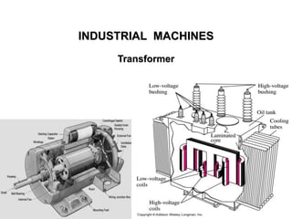
  • 6. 6 CONSTRUCTION OF A TRANSFORMER i) The core is made of silicon steel having low hysteresis loss and high permeability. ii) Core is laminated and electrically separated by a thin coating of insulating material in order to reduce eddy current loss and the no- load current. iii) Instead of placing primary on one limb and secondary on the other one-half of each winding is wound on one limb to ensure tight coupling between the two windings and reduce flux leakage. iv) The winding resistances R1 and R2 are minimized to reduce I2R loss, reduce winding temperature and to ensure high efficiency. Types of Transformers The manner in which the primary and secondary are wound on the core, transformers are of two types (i) core-type and (ii) shell-type Lecture Notes by Dr.R.M.Larik
  • 7. 7 CONSTRUCTION OF A TRANSFORMER (Contd.) Core-type transformer • In a core-type transformer, there is a single path for the magnetic circuit. • Half of the primary winding and half of the secondary winding are placed round each limb to reduce flux leakage. Shell-type transformer • Both the windings are placed round the central limb to make double path for magnetic circuit • The other two limbs provide a low- reluctance flux path. Lecture Notes by Dr.R.M.Larik
  • 8. 8 CONSTRUCTION OF A TRANSFORMER (Contd.) Windings • The windings consist of the current-carrying insulated copper conductors wound around the sections of the core. • The windings are usually arranged concentrically around the core leg. • Concentric coils are typically wound over cylinders with spacers attached so as to form a duct between the conductors and the cylinder. • The flow of liquid through the windings is based on natural convection, and is controlled by using the barriers placed within the winding. Lecture Notes by Dr.R.M.Larik
  • 9. 9 CONSTRUCTION OF A TRANSFORMER (Contd.) Accessory Equipment Liquid-Level Indicator A liquid-level indicator is a standard feature on liquid-filled transformer tanks, since the liquid medium is critical for cooling and insulation. Pressure-Relief Devices Pressure-relief devices are mounted on transformer tanks to relieve excess internal pressures that might build up during operating conditions. Liquid-Temperature Indicator Liquid-temperature indicators measure the temperature of the internal liquid. Winding-Temperature Indicator A winding-temperature simulation method is used to approximate the hottest spot in the winding. Lecture Notes by Dr.R.M.Larik
  • 10. 10 CONSTRUCTION OF A TRANSFORMER (Contd.) Accessory Equipment (Contd.) Sudden-Pressure Relay A sudden- (or rapid-) pressure relay is intended to indicate a quick increase in internal pressure that can occur when there is an internal fault Desiccant (Dehydrating) Breathers Desiccant breathers use a material such as silica gel to allow air to enter and exit the tank, removing moisture as the air passes through. Liquid-Preservation Systems Liquid-temperature indicators measure the temperature of the internal liquid Lecture Notes by Dr.R.M.Larik
  • 11. 11 CONSTRUCTION OF A TRANSFORMER (Contd.) Liquid-Preservation Systems • Preservation systems isolates the transformer’s internal environment from the external environment. • Conservator system involve the use of a separate auxiliary tank. • The auxiliary tank is allowed to “breathe,” usually through a dehydrating breather Buchholz Relay Its purpose is to detect faults that may occur in the transformer resulting in generation of gases. Lecture Notes by Dr.R.M.Larik
  • 12. 12 CONSTRUCTION OF A TRANSFORMER (Contd.) Cooling of Transformers Heat is produced in a transformer by the iron losses in the core and I2R loss in the windings. To prevent undue temperature rise, this heat is removed by cooling. • In small transformers (< 50 kVA), natural air cooling is sufficient • Medium size power or distribution transformers are cooled by housing them in tanks filled with oil. • For large transformers, external radiators are added to increase the cooling surface of the oil filled tank. • The oil circulates around the transformer and moves through the radiators where the heat is released to surrounding air. • Sometimes cooling fans blow air over the radiators to accelerate the cooling process. Lecture Notes by Dr.R.M.Larik
  • 13. 13 CONSTRUCTION OF A TRANSFORMER (Contd.) Lecture Notes by Dr.R.M.Larik
  • 14. 14 IDEAL TRANSFORMER • No winding resistance, no leakage flux and no iron losses in the cor • When an alternating voltage V1 is applied to the primary, it draws a small magnetizing current Im which lags behind the applied voltage by 90°. • Im produces an alternating flux Φ which is proportional to and in phase with it • The alternating flux Φ induces e.m.f. E1 in the primary and e.m.f. E2 in the secondary. • E1 is equal to and in opposition to V1 (Lenz’s law) and both E1 and E2 lag behind flux Φ by 90° Lecture Notes by Dr.R.M.Larik
  • 15. 15 E.M.F. EQUATION OF A TRANSFORMER An alternating voltage V1 of frequency f is applied to the primary The sinusoidal flux f produced by the primary can be represented as: f= fm sin wt The instantaneous e.m.f. e1 induced in the primary is: e1 = – N1 dϕ dt = – N1 d dt (fm sin ωt) = – ω N1fmcosωt = – 2p f N1fmcosωt = 2p f N1fm sin (ωt – 90o) (i) = Em1 sin(ωt - 90o)Em1 = 2 πfN1ϕm It is clear from above equation that e.m.f. e1 induced in the primary lags behind the flux f by 90°. Lecture Notes by Dr.R.M.Larik
  • 16. 16 E.M.F. EQUATION OF A TRANSFORMER (Contd.) Maximum value of induced e.m.f. in the primary is: Em1= 2p f N1ϕm The r.m.s. value E1 of the primary e.m.f. is E1 = Em1 2 = 2π f N1ϕm 2 or E1 = 4.44 f N1 ϕm = 4.44 f N1BmA Similarly E2 = 4.44 f N2ϕm = 4.44 f N2BmA where ϕm= Bm (flux density) x A (cross-sectional area of core) In an ideal transformer, E1 = V1 and E2 =V2. Lecture Notes by Dr.R.M.Larik
  • 17. 17 VOLTAGE TRANSFORMATION RATIO From the induced e.m.f equations: E2 E1 = N2 N1 = K The constant K is called voltage transformation ratio. For an Ideal Transformer E1 = V1 and E2 = V2 as there is no voltage drop in the windings E2 E1 = V2 V1 = N2 N1 = K As there are no losses the volt-amperes input to the primary are equal to the output volt-amperes i.e. V1I1= V2I2 or I2 I1 = V1 V2 = 1 KLecture Notes by Dr.R.M.Larik
  • 18. 18 NUMERICAL PROBLEMS Problem 1(a) An ideal 25 kVA transformer has 500 turns on the primary and 40 turns on the secondary winding. The primary is connected to 3000 V, 50 Hz supply. Calculate (i) full-load primary and secondary currents (ii) the secondary e.m.f. and (iii) the maximum core flux. Solution: Rating = 25 kVA, N1 = 500, N2 = 40, V1 = 3000 V, f = 50 Hz I1 ?, I2 ?, E2?, Φm ? Transformation ratio K = N2 N1 = 40 500 = 0.08 i) Primary current I1 = VA V1 = 25 𝑥 103 3000 = 8.33 A Lecture Notes by Dr.R.M.Larik
  • 19. 19 NUMERICAL PROBLEMS (Contd.) Problem 1(a) Solution(Contd.) Secondary current I2 = I1 K = 8.33 0.08 = 104.2 A ii) E2 E1 = K E2 = K x E1 = 0.08 x 3000 = 240 V iii) E1 = 4.44 x f x N1 x Φm 3000 = 4.44 x 50 x 500 x Φm Φm = 3000 4.44 x 50 x 500 = 27 x 10 -3Wb = 27 mWb Lecture Notes by Dr.R.M.Larik
  • 20. 20 NUMERICAL PROBLEMS (Contd.) Problem 1(b) A single-phase transformer has 400 primary and 1000 secondary turns. The net cross-sectional area of the core is 60 cm2. If the primary winding be connected to a 50-Hz supply at 520 V, calculate (i) the peak value of flux density in the core (ii) the voltage induced in the secondary winding. Problem 1(c) A single phase transformer has 500 turns in the primary and 1200 turns in the secondary. The cross-sectional area of the core is 80 sq. cm. If the primary winding is connected to a 50 Hz supply at 500 V, calculate (i) Peak flux-density, and (ii) Voltage induced in the secondary. Solution N1 = 500, N2 = 1200, A = 80 cm2, V1 = 500 V, f = 50 Hz Bm ?, V2 ? Lecture Notes by Dr.R.M.Larik
  • 21. 21 NUMERICAL PROBLEMS (Contd.) Problem 1(c) Solution(Contd.) E1= 4.44 x f x N1 x Φm 500 = 4.44 x 50 x 500 x Φm Φm = 4.5x10⁻³Wb i) Peak flux density Bm = Φm/A = 4.5 x 10⁻³ 80 x 10−4 = 0.5625 Wb/m2 ii) V2 V1 = N2 N1 V2 = V1 x N2 N1 = 500 x 1200 500 = 1200 V Lecture Notes by Dr.R.M.Larik
  • 22. 22 NUMERICAL PROBLEMS (Contd.) Problem 1(d) A 25 kVA, single-phase transformer has 250 turns on the primary and 40 turns on the secondary winding. The primary is connected to 1500 Volt, 50 Hz supply. Calculate (i) Primary and Secondary currents on full-load, (ii) Secondary e.m.f., and (iii) maximum flux in the core. Problem 2(a) A single-phase 2200/250, 50 Hz transformer has a net core area of 36 cm2 and a maximum flux density of 6 Wb/m2. Calculate the number of turns of primary and secondary. Solution: E1 = 2200 V, E2 = 250 V, f = 50 Hz, A = 36 cm2, Bm = 6 Wb/m2 N1 ?, N2 ? Lecture Notes by Dr.R.M.Larik
  • 23. 23 NUMERICAL PROBLEMS (Contd.) Problem 2(a) Solution (Contd.): Peak flux Φm = Bm (Wb/m2) x A (m2) = 6 x 36 x 10-4 = 0.0216 Wb RMS primary induced e.m.f. E1 = 4.44 x f x N1 x Φm N1 = E1 4.44 x f x ∅m = 2200 4.44 x 50 x 0.0216 = 459 N2 = E2 4.44 x f x ∅m = 250 4.44 x 50 x 0.0216 = 52 Problem 2(b) A sinusoidal flux 0.02 Wb (max.) links with 55 turns of a transformer secondary. Calculate the r.m.s. value of the induced e.m.f. in the secondary. The supply frequency is 50 Hz. Lecture Notes by Dr.R.M.Larik
  • 24. 24 WINDING POLARITY Dot Convention • It is not possible to tell the secondary polarity of ideal transformer unless its windings are physically examined. • To overcome the problem dot convention of transformer winding is used • The dot appearing on end of the winding tells the polarity of voltage and currents of secondary side. • If the primary voltage is positive at the dotted end of the winding, then the secondary voltage will be positive at the dotted end also. • If the primary current of the transformer flows into the dotted end of the primary, the secondary current will flow out of the dotted end of secondary • • Lecture Notes by Dr.R.M.Larik
  • 25. 25 POWER IN IDEAL TRANSFORMER The power supplied to the transformer by the primary circuit is given as: Pin = V1 I1 cos Φ1 Φ1 is the angle between the primary voltage and primary current. The power supplied by the transformer secondary circuit to its load is as: Pout = V2 I2 cos Φ2 Φ2 is the angle between the secondary voltage and secondary current. Since voltage and current angles are unaffected by an ideal transformer Φ1 - Φ2 = 0 Primary and secondary windings of an ideal transformer have the same power factor Lecture Notes by Dr.R.M.Larik
  • 26. 26 POWER IN IDEAL TRANSFORMER (Contd.) Comparison of Input and Output Power The output power of a transformer is: Pout = V2 I2 cos Φ Applying the transformation ratio: V2 = V1 x K and I2 = I1 / K Pout = (V1 x K) (I1 / K ) cos Φ Pout = V1 I1 cos Φ = Pin Thus, output power of an ideal transformer is equal to its input power. The same relationship applies to reactive power and apparent power. Lecture Notes by Dr.R.M.Larik
  • 27. 27 PRACTICAL TRANSFORMER Iron Losses • The iron losses depend upon the supply frequency, core volume and maximum flux density in the core • Magnitude of iron losses is quite small in a practical transformer. Winding Resistances When current flows through the windings, there will be power loss and a loss in voltage due to IR drop, hence, E1 will be less than V1 whereas V2 will be less than E2.Lecture Notes by Dr.R.M.Larik
  • 28. 28 PRACTICAL TRANSFORMER (Contd.) Leakage Reactances • Primary current produces some flux Φ1 not linked with the secondary winding • Secondary current produces some flux Φ2 not linked with the primary winding. • The primary and secondary leakage flux Φ1 , Φ2 introduce inductive reactances X1 and X2 in series with the primary and secondary windings Lecture Notes by Dr.R.M.Larik
  • 29. 29 PRACTICAL TRANSFORMER (Contd.) Transformer on No Load • The primary will draw a small current I0 to supply the iron losses and small amount of copper loss. • Hence, primary no load current I0 is not 90° behind the applied voltage V1 but lags it by an angle Φ0 < 90° • The component IW, in phase with the applied voltage V1, is known as active (working) or iron loss component and supplies the iron loss and a small primary copper loss. IW = I0 cos Ф0Lecture Notes by Dr.R.M.Larik
  • 30. 30 PRACTICAL TRANSFORMER (Contd.) Transformer on No Load (Contd.) • The component Im lagging behind V1 by 90°, known as magnetizing component, produces the mutual flux Φ in the core. Im= I0 sin ϕ0 Clearly, I0 is phasor sum of Im and IW, hence, Io = Im 2 + IW 2 No load p,f, cosϕo = IW Io • No load primary copper loss (i.e. I0 2 R1 ), being very small, may be neglected, hence: No load input power, W0 = Iron loss = V1 I0cosΦ0 • At no load, there is no secondary current so V2 = E2 and on the primary side, the drops in R1 and X1are very small, hence V1 = E1. Lecture Notes by Dr.R.M.Larik
  • 31. 31 PRACTICAL TRANSFORMER (Contd.) Problem 3(a) A 2200/200 V transformer draws a no-load primary current of 0.6 A, and absorbs 400 watts. Find the magnetizing and iron loss currents. Solution: E1 = 2200, E2 = 200, Io = 0.6 A, No load input = 400 W Iw ?, Im ? Iron loss current Iw = No load input (W) Primary voltage = 400 2200 = 0.182 A Io 2 = Iw 2 + Im 2 Im = Io 2 − Iw 2 = (0.6)2 − (0.182)2 = 0.572 A Lecture Notes by Dr.R.M.Larik
  • 32. 32 PRACTICAL TRANSFORMER (Contd.) Problem 3(b) A 2200/250 V transformer takes 0.5 A at a p.f. of 0.3 on open circuit. Find magnetizing and working components of no-load primary current. Problem 3(c) A transformer takes a current of 0.6 A, and absorbs 64 W when primary is connected to its normal supply of 200 V, 50 Hz; the secondary being an open circuit. Find the magnetizing and iron loss currents. Solution: Io = 0.6 A, Wo = 64 W, E1 = 200 V, f = 50 Hz Iw ?, Im ? No load primary power Wo = V1 Io Cos Φo Iron loss current Iw = Io Cos Φo = Wo V1 Lecture Notes by Dr.R.M.Larik
  • 33. 33 PRACTICAL TRANSFORMER (Contd.) Problem 3(c) Solution (Contd.): Iron loss current Iw = 64 200 = 0.32 A Io 2 = Iw 2 + Im 2 Magnetizing current Im = Io 2 − Iw 2 = (0.6)2 − 0.32 2 = 0.507 A Problem 3(d): A 230/2300 V transformer takes a no-load current of 6.5 A and absorbs 187 W. If the resistance of primary is 0.06  find (i) the core loss (ii) no-load power factor (iii) active component of current and (iv) magnetizing current. Lecture Notes by Dr.R.M.Larik
  • 34. 34 LOADING OF TRANSFORMER Ideal Transformer on Load • The secondary e.m.f. E2 will cause a current I2 to flow through the load. I2= E2 ZL = V2 ZL • In the case of inductive load the current I2 lags behind V2 (or E2) by Φ2. Lecture Notes by Dr.R.M.Larik
  • 35. 35 LOADING OF TRANSFORMER (Contd.) Ideal Transformer on Load (Contd.) • I2 sets up an m.m.f. N2 I2which produces a flux Φ2, in the opposite direction to the main flux Φ (set up in the primary by the magnetizing current), changing the main flux in the core and back e.m.f E1 tends to be reduced • Momentarily the V1 gains upper hand over E1 and causes more current to flow in the primary and the primary develops an m.m.f. which exactly counterbalances the secondary m.m.f. N2 I2. • The primary current I1 flows such that: N1 I1 = N2 I2 I1 = N2 N1 I2 = K I2 • Thus as the secondary current increases, the primary current I1(= K I2 ) also increases to keep the mutual flux Φ constant. • The power input automatically increases with increase in output. Lecture Notes by Dr.R.M.Larik
  • 36. 36 LOADING OF TRANSFORMER (Contd.) Ideal Transformer on Load (Contd.) Phasor diagram: • The value of K has been assumed unity so that primary phasors are equal to secondary phasors. • Secondary current I2 lags behind V2 (or E2) by Φ2 causing a primary current I1 = K I2 = 1x I2 which is in anti-phase with it. i) ϕ1 = ϕ2 or cos ϕ1 = cos ϕ2 ii) Since there are no losses in an ideal transformer, input primary power is equal to the secondary output power i.e., V1I1 cosϕ1 = V2I2 cosϕ2 Lecture Notes by Dr.R.M.Larik
  • 37. 37 LOADING OF TRANSFORMER (Contd.) Problem 4(a) An ideal transformer having 90 turns on the primary and 2250 turns on the secondary is connected to 200 V, 50 Hz supply. The load across the secondary draws a current of 2 A at a p.f. of 0.8 lagging. Calculate (i) the value of primary current and (ii) the peak value of flux linked with the secondary. Draw the phasor diagram. Solution: N1 = 90, N2 = 2250, V2 = 200 V, f = 50 Hz, I2= 2 A, Cos Φ2 = 0.8 lagging I1 ?, Φm? Transformation ratio K = N2 N1 = 2250 90 = 25 i) Primary current I1 = K I2 = 25 x 2 = 50 A Lecture Notes by Dr.R.M.Larik
  • 38. 38 LOADING OF TRANSFORMER (Contd.) Problem 4(a) Solution (Contd.): ii) Primary induced voltage E1= 4.44 x f x N1 x Φm Φm= E1 4.44 x f x N1 = 200 4.44 x 50 x 90 = 0.01 Wb Secondary induced voltage E2 = K x E1 = 25 x 200 = 5000 V Secondary current phase angle Φ2 = Cos -1 0.8 = 36.9o Lecture Notes by Dr.R.M.Larik
  • 39. 39 LOADING OF TRANSFORMER (Contd.) Problem 4(b) An ideal transformer has 1000 turns on its primary and 500 turns on its secondary. The driving voltage on the primary side in 100 V and the load resistance is 5 . Calculate V2, I1 and I2. Lecture Notes by Dr.R.M.Larik
  • 40. 40 LOADING OF TRANSFORMER (Contd.) Practical Transformer on Load It is assumed that (i) transformer has no winding resistance and leakage flux (ii) transformer has winding resistance and leakage flux. No winding resistance and leakage flux • With this assumption, V2 = E2 and V1 = E1, • Take the case of inductive load causing the secondary current I2 to lag the secondary voltage V2 by Φ2. Lecture Notes by Dr.R.M.Larik
  • 41. 41 LOADING OF TRANSFORMER (Contd.) Practical Transformer on Load (Contd.) No winding resistance and leakage flux (Contd.) The total primary current I1 must supply: a) The no-load current I0 tomeet the iron losses in the transformer and provides flux in the core. b) A current I'2 to counteract the demagnetizing effect of secondary current I2 andmagnitude of I'2 will be such that: N1 I'2 = N2 I2 or I2 ′ = N2 N1 I2 = K I2 The total primary current I1 is the phasor sum of I'2 and I0 i.e., I1= I'2 +I0 where I'2 = - K I2 Current I'2 is 180° out of phase with I2.Lecture Notes by Dr.R.M.Larik
  • 42. 42 LOADING OF TRANSFORMER (Contd.) Practical Transformer on Load (Contd.) Phasor diagram • Both E1 and E2 lag behind the mutual flux Φ by 90°. • The primary current I'2 neutralizes the demagnetizing effect of secondary current I2. • I'2 = K I2 and is anti-phase with I2. • The phasor sum of I'2 and no load current I0 gives the total primary current I1. • The value of K is assumed to be unity Primary p.f. = cos Φ1 Secondary p.f. = cos Φ2 Primary input power = V1 I1 cos Φ1 Secondary output power = V2 I2 cos Φ2 Lecture Notes by Dr.R.M.Larik
  • 43. 43 LOADING OF TRANSFORMER (Contd.) Practical Transformer on Load (Contd.) Transformer with resistance and leakage reactance • Due to voltage drop in R1 and X1 the primary e.m.f. E1 is less than V1. • Due to voltage drop in R2 and X2 the secondary terminal voltage V2 is less than the secondary e.m.f. E2. Lecture Notes by Dr.R.M.Larik
  • 44. 44 LOADING OF TRANSFORMER (Contd.) Practical Transformer on Load (Contd.) Practical Transformer with resistance and leakage reactance (Contd.) • The inductive load causes the secondary current I2 to lag behind the secondary voltage V2 by ϕ2. • The total primary current I1 must meet two requirements: a) Supply the no-load current I0 to meet the iron losses in the transformer and to provide flux in the core. b) Supply a current I'2 to counteract the demagnetizing effect of secondary current I2. • The magnitude of I'2 will be such that: N1 I'2 = N2 I2 I2 ′ = N2 N1 I2 = K I2 Lecture Notes by Dr.R.M.Larik
  • 45. 45 LOADING OF TRANSFORMER (Contd.) Practical Transformer with resistance and leakage reactance (Contd.) The total primary current I1 will be the phasor sum of I'2 and I0 I1 = I'2 + I0 where I'2 = - K I2 V1 = - E1 + I1 (R1 + jX1) where I1 = I0 + (- K I2) = - E1 + I1 Z1 V2 = E2 - I2 (R2 + jX2) = E2 - I2 Z2 Phasor diagram. • Both E1 and E2 lag the mutual flux ϕ by 90°. • The primary current I'2 neutralizes the demagnetizing effect of secondary current I2. • I'2 = K I2 and is opposite to I2. • The phasor sum of I'2 and no load current I0 is the total primary current I1 Lecture Notes by Dr.R.M.Larik
  • 46. 46 LOADING OF TRANSFORMER (Contd.) Practical Transformer on Load (Contd.) Phasor diagram (Contd.) • Back e.m.f. E1 opposes the applied voltage V1 • If I1 R1 (in phase with I1) and I1 X1 (90° ahead of I1) is added to - E1, we get the applied primary voltage V1. • The phasor E2 represents the induced e.m.f. in the secondary by the mutual flux Φ. • The secondary terminal voltage V2 is shown after subtracting I2 R2 and I2 X2 from E2. Load power factor = cos ϕ2 Primary power factor = cos ϕ1 Input power to transformer, P1 = V1 I1 cos ϕ1 Output power of transformer, P2 = V2 I2 cos ϕ2 Lecture Notes by Dr.R.M.Larik
  • 47. 47 LOADING OF TRANSFORMER (Contd.) Problem 5(a) A single-phase transformer with a ratio of 440/110 V takes a no-load current of 5A at 0.2 power factor lagging. If the secondary supplies a current of 120 A at a p.f. of 0.8 lagging, estimate the current taken by the primary. Solution: V1= 440 V, V2 = 110 V, Io = 5 A, Cos Φo = 0.2, I2 = 120 A, Cos Φ2 = 0.8 lag I1 ?, Transformation ratio K = V2 V1 = 110 440 = 0.25 I2 ′ =K x I2 = 0.25 x 120 = 30 A Φ2 = Cos-1 0.8 = 36.87o Φo = Cos-1 0.2 = 78.46o Angle between I2 ′ and Io = 78.46o − 36.87o = 41.59o Lecture Notes by Dr.R.M.Larik
  • 48. 48 LOADING OF TRANSFORMER (Contd.) Problem 5(a) Solution(Contd.): I1 = Io 2 + I2 ′ 2 + 2 Io I2 ′ Cos 41.59o = 5 2 + 30 2 + 2 x 5 x 30 x Cos 41.59o = 33.9 A Lecture Notes by Dr.R.M.Larik
  • 49. 49 LOADING OF TRANSFORMER (Contd.) Problem 5(b) A single-phase transformer has 1000 turns on the primary and 200 turns on the secondary. The no load current is 3 amp. at a p.f. of 0.2 lagging. Calculate the primary current and power-factor when the secondary current is 280 amp. at a p.f. of 0.80 lagging. Lecture Notes by Dr.R.M.Larik
  • 50. 50 IMPEDANCE RATIO OF TRANSFORMER Z2= V2 I2 Z1 = V1 I1 Z2 Z1 = V2 V1 x I1 I2 Z2 Z1 = K2 Impedance ratio (Z2/Z1) is equal to the square of voltage transformation ratio. Similarly, R2 R1 = K2 and X2 X1 = K2 Consider a transformer having impedance Z2 in the secondary. Lecture Notes by Dr.R.M.Larik
  • 51. 51 SHIFTING IMPEDANCES IN A TRANSFORMER The resistance and reactance of one winding can be transferred to the other to make the analysis of the transformer simple. When secondary resistance / reactance is transferred to primary, called equivalent secondary resistance / reactance referred to primary and is denoted by R'2 or X'2, it is divided by K2. Referred to primary Lecture Notes by Dr.R.M.Larik
  • 52. 52 SHIFTING IMPEDANCES IN A TRANSFORMER (Contd.) Referred to secondary When primary resistance / reactance is transferred to secondary, called equivalent primary resistance / reactance referred to the secondary and is denoted by R'1 or X'1, it is multiplied by K2. Lecture Notes by Dr.R.M.Larik
  • 53. 53 SHIFTING IMPEDANCES IN A TRANSFORMER (Contd.) Problem 6(a) A 30 kVA, 2400/120 V, 50 Hz transformer has a high voltage winding resistance of 0.1  and a leakage reactance of 0.22 . The low voltage winding resistance is 0.035  and the leakage reactance is 0.012 . Find the equivalent winding resistance, reactance and impedance referred to the (i)high voltage side and (ii)the low-voltage side. Solution: Trafo rating = 30 kVA, V1 = 2400 V, V2 = 120 V, R1 = 0.1 , X1 = 0.22 , R2= 0.035 , X2 = 0.01  R01 ?, X01 ?, Z01 ?, R02 ?, X02 ?, Z02 ? Transformation ratio K = V2 V1 = 120 2400 = 0.05 R01 = R1 + R2 ′ = R1 + R2 K2 = 0.1 + 0.035 0.052 = 14.1 Ω Lecture Notes by Dr.R.M.Larik
  • 54. 54 SHIFTING IMPEDANCES IN A TRANSFORMER (Contd.) Problem 6(a) Solution (Contd.): X01 = X1 + X2 ′ = X1 + X2 K2 = 0.22 + 0.012 0.052 = 5.02 Ω Z01= R01 2 + X01 2 = 14.1 2 + 5.02 2 = 15 Ω R02= R2 + R1 ′ = R2 + K2 x R1 = 0.035 + (0.05)2 x 0.1 = 0.03525 Ω X02 = X2 + X1 ′ = X2 + K2 x X1 = 0.012 + (0.05)2 x 0.22 = 0.01255 Ω Z02 = R02 2 + X02 2 = 0.03525 2 + 0.01255 2 = 0.0374 Ω Problem 6(b) A 10 kVA, 2000/400 v single-phase transformer has R1 = 5 ; X1 = 12 ; R2= 0.2  and X2 = 0.48 . Determine the equivalent impedance of the transformer referred to (i) primary side (ii) secondary side. Lecture Notes by Dr.R.M.Larik
  • 55. 55 SHIFTING IMPEDANCES IN A TRANSFORMER (Contd.) Problem 6(c) A 100 kVA, 1100/220 V, 50 Hz, single-phase transformer has a leakage impedance of (0.1 +J 0.40) ohm for the H.V. winding and (0.006 +J 0.015) ohm for the L.V. winding. Find the equivalent winding resistance, reactance and impedance referred to the H.V. and L.V. sides. Problem 7(a) A 50 kVA, 4,400/220 V transformer has R1 = 3.45 , R2 = 0.009 . The values of reactances are X1 = 5.2  and X2 = 0.015 . Calculate for the transformer (i) equivalent resistance as referred to primary (ii) equivalent resistance as referred to secondary (iii) equivalent reactance as referred to both primary and secondary (iv) equivalent impedance as referred to both primary and secondary (v) total Cu loss, first using individual resistances of the two windings and secondly, using equivalent resistances as referred to each side. Lecture Notes by Dr.R.M.Larik
  • 56. 56 SHIFTING IMPEDANCES IN A TRANSFORMER (Contd.) Problem 7(a) Solution (Contd.): Trafo rating = 50 kVA, V1 = 4400 V, V2 = 220 V, R1 = 3.45 , X1= 5.21 , R2= 0.009 , X2 = 0.015  R01 ?, X01 ?, Z01 ?, R02 ?, X02 ?, Z02 ? Copper loss using i) individual resistances of primary and secondary and using ii) equivalent resistances ? Transformation ratio K = V2 V1 = 220 4400 = 0.05 I1 = VA V1 = 50000 4400 = 11.36 A I2= VA V2 = 50000 220 = 227 A R01 = R1 + R2 ′ = R1 + R2 K2 = 3.45 + 0.009 (0.05)2 = 7.05 Ω Lecture Notes by Dr.R.M.Larik
  • 57. 57 SHIFTING IMPEDANCES IN A TRANSFORMER (Contd.) Problem 7(a) Solution (Contd.): X01= X1 + X2 ′ = X1 + X2 K2 = 5.2 + 0.015 (0.05)2 = 11.2 Ω Z01 = 𝑅01 2 + 𝑋01 2 = 7.05 2 + 11.2 2 = 13.23 Ω R02 = R2 + R1 ′ = R2 + K2 x R1 = 0.009 + (0.05)2 x 3.45 = 0.0176 Ω X02 = X2 + X1 ′ = X2 + K2 x X1 = 0.015 + (0.05)2 x 5.2 = 0.028 Ω Z02 = 𝑅02 2 + 𝑋02 2 = 0.0176 2 + 0.028 2 = 0.033 Ω Total copper loss = I1 2 x R1+ I2 2 x R2 = (11.36)2 x 3.45 = (227)2 x 0.009 = 910 W Also Cu loss = I1 2 x R01 = (11.36)2 x 7.05 = 910 W = I2 2 x R02 = (227)2 x 0.0176 = 910 W Lecture Notes by Dr.R.M.Larik
  • 58. 58 SHIFTING IMPEDANCES IN A TRANSFORMER (Contd.) Problem 7(b) A 100 kVA , 2200/440 V transformer has R1 = 0.3 ; X1 = 1.1  ; R2 = 0.01  and X2 = 0.035 . Calculate (i) the equivalent impedance of the transformer referred to primary and (ii) total copper losses. Lecture Notes by Dr.R.M.Larik
  • 59. 59 EQUIVALENT CIRCUIT OF TRANSFORMER • The parallel circuit R0 - X0 is no-load equivalent circuit. • The resistance R0 represents the core losses supplied by the current IW. • The inductive reactance X0 represents a loss-free coil which passes the magnetizing current Im. • The phasor sum of IW and Im is the no-load current I0 of the transformer. Lecture Notes by Dr.R.M.Larik
  • 60. 60 EQUIVALENT CIRCUIT OF TRANSFORMER (Contd.) • Equivalent circuit has created two circuits separated by an ideal transformer whose function is to change values according to the equation: E2 E1 = N2 N1 = I2 ′ I2 • When the transformer is on no-load, there is no current in the secondary winding, however, the primary draws a small no-load current I0. • When load ZL is connected to the secondary circuit the voltage E2 induced in the secondary by mutual flux will produce a secondary current I2. V2 = E2 - I2 (R2 + j X2 ) = E2 - I2 Z2 Lecture Notes by Dr.R.M.Larik
  • 61. 61 EQUIVALENT CIRCUIT OF TRANSFORMER (Contd.) • When the transformer is loaded to carry the secondary current I2, the primary current consists of no-load current I0 to provide • Since the transformer is ideal, the primary induced voltage E1 can be calculated from the relation: E1 E2 = N1 N2 • If we add I1R1 and I1X1 drops to E1, we get the primary input voltage V1 • If we add I1R1 and I1X1 drops to E1, we get the primary input voltage V1 V1 = - E1 + I1 (R1 + j X1) = - E1 + I1 Z1 – magnetizing current, – the current required to supply the core losses – primary current I'2 (= K I2) required to supply the load on the secondary. Lecture Notes by Dr.R.M.Larik
  • 62. 62 SIMPLIFIED EQUIVALENT CIRCUIT OF A LOADED TRANSFORMER • The no-load current I0 is small as compared to the rated primary current, hence, voltage drops in R1 and X1 due to I0 can be neglected. • The equivalent circuit can be simplified by transferring the shunt circuit R0 - X0 to the input terminals. Lecture Notes by Dr.R.M.Larik
  • 63. 63 SIMPLIFIED EQUIVALENT CIRCUIT OF A LOADED TRANSFORMER Equivalent circuit referred to primary If all the secondary quantities are referred to the primary, we get the equivalent circuit of the transformer referred to the primary Lecture Notes by Dr.R.M.Larik
  • 64. 64 SIMPLIFIED EQUIVALENT CIRCUIT OF A LOADED TRANSFORMER Equivalent circuit referred to primary (Contd.) When secondary quantities are referred to primary, impedances are divided by K2, voltages are divided by K and currents are multiplied by K. R2 ′ = R2 K2 ; X2 ′ = X2 K2 ; ZL ′ = ZL K2 ; V2 ′ = V2 K ; I2 ′ = K I2 ; Z01= R01 + j X01 where R01 = R1 + R'2 ; X01 = X1 + X'2 The equivalent circuit of the transformer can be further reduced Lecture Notes by Dr.R.M.Larik
  • 65. 65 SIMPLIFIED EQUIVALENT CIRCUIT OF A LOADED TRANSFORMER Equivalent circuit referred to primary (Contd.) Phasor diagram • The referred value of load voltage V'2 is chosen as the reference. • The referred value of load current I'2 is shown lagging V'2 by angle Φ2. • For a given value of V'2 both I'2 and Φ2 are determined by the load. • The voltage drop I'2 R01 is in phase with I'2 and the voltage drop I'2 X01, leads I'2 by 90°. Lecture Notes by Dr.R.M.Larik
  • 66. 66 SIMPLIFIED EQUIVALENT CIRCUIT OF A LOADED TRANSFORMER Equivalent circuit referred to secondary If all the primary quantities are referred to secondary, we get the equivalent circuit of the transformer referred to secondary Lecture Notes by Dr.R.M.Larik
  • 67. 67 SIMPLIFIED EQUIVALENT CIRCUIT OF A LOADED TRANSFORMER Equivalent circuit referred to secondary (Contd.) When primary quantities are referred to secondary impedances are multiplied by K2, voltages are multiplied by K and currents are divided by K R'1 = K2 R1 ; X'1 = K2 X1 ; V'2 = K V1 ; I'1 = I1/K Z02 = R02 + j X02 where R02 = R2 + R'1 ; X02 = X2 + X'1 The equivalent circuit of the transformer can be further reduced Lecture Notes by Dr.R.M.Larik
  • 68. 68 SIMPLIFIED EQUIVALENT CIRCUIT OF A LOADED TRANSFORMER Equivalent circuit referred to secondary (Contd.) Phasor diagram • The load voltage V2 is chosen as reference. • The load current I2 is shown lagging the load voltage V2 by angle ϕ2. • The voltage drop I2 R02 is in phase with I2 and the voltage drop I2 X02 leads I2 by 90°. • Current I'W is in phase with V'1 & the current I'm lags behind V'1 by 90° • The sum of I'W and I'm gives the referred value of no-load current I'0. • The sum of I'0 and I2 gives the referred primary current I'1 (= I1/K). Lecture Notes by Dr.R.M.Larik
  • 69. 69 SIMPLIFIED EQUIVALENT CIRCUIT OF A LOADED TRANSFORMER Problem 8(a): A 10 kVA, 2000/400 V single-phase transformer has the following data: R1 = 5 ; X1 = 12 ; R2 = 0.2 ; X2 = 0.48  Determine the secondary terminal voltage at full load, 0.8 p.f. lagging when the primary supply voltage is 2000 V. Solution: Trafo rating = 10 kVA, V1 = 2000 V, V2 = 400 V, R1 = 5 , X1 = 12 , R2= 0.2 , X2 = 0.48 , P.f. = 0.8 Secondary terminal voltage at full load V2 ? Transformation ratio K = V2 V1 = 400 2000 = 0.2 R02 = R2 + R1 ′ = R2 + K2 x R1 = 0.2 + (0.2)2 x 5 = 0.4 Ω X02 = X2 + X1 ′ = X2 + K2 x X1 = 0.48 + (0.2)2 x 12 = 0.96 Ω Lecture Notes by Dr.R.M.Larik
  • 70. 70 SIMPLIFIED EQUIVALENT CIRCUIT OF A LOADED TRANSFORMER Problem 8(a): Solution (Contd.): Full load secondary current I2 = VA V2 = 10000 400 = 25 A Φ2 = Cos -1 0.8 = 36.9o, Sin Φ2 = Sin 36.9o = 0.6 Approximate voltage drop = I2 (R02 Cos Φ2 + X02 Sin Φ2) = 25 (0.4 x 0.8 + 0.96 x 0.6) = 22.4 V Secondary terminal voltage at full load V2 = 400 – 22.4 = 377.6 V Problem 8(b): A 230/460 V transformer has a primary resistance of 0.2  and reactance of 0.5  and the corresponding values for the secondary are 0.75  and 1.8  respectively. Find the secondary terminal voltage when supplying 10 A at 0.8 p.f. lagging.Lecture Notes by Dr.R.M.Larik
  • 71. 71 VOLTAGE REGULATION The voltage regulation of a transformer is the arithmetic difference between the no-load secondary voltage (0V2) and the secondary voltage V2 on load expressed as percentage of no-load voltage i.e. %age voltage regulation = 0V2 − V2 0V2 x 100 0V2- V2= I2 R02cosϕ2± I2 X02sin ϕ2 The +ve sign is for lagging p.f. and -ve sign for leading p.f. Percentage voltage regulation of the transformer will be the same whether primary or secondary side is considered. Lecture Notes by Dr.R.M.Larik
  • 72. 72 VOLTAGE REGULATION Problem 8(c): The primary and secondary windings of a 40 kVA, 6600/250 V single- phase transformer has resistance of 10  and 0.02  respectively. The leakage reactance of the transformer referred to primary side is 35 . Calculate percentage voltage regulation of the transformer when applying full-load current at p.f. 0.8 lagging. Solution: Trafo rating = 40 kVA, V1 = 6600 V, V2 = 230 V, R1 = 10 , X01 = 35 , R2 = 0.02 , Cos Φ2 = 0.8 Percentage voltage regulation at full load and 0.8 p.f. ? Transformation ratio K = V2 V1 = 230 6600 = 0.03788 R01 = R1 + R2 ′ = R1 + R2 K2 = 10 + 0.02 (0.03788)2 = 23.932 Ω Lecture Notes by Dr.R.M.Larik
  • 73. 73 VOLTAGE REGULATION Problem 8(c): Solution (Contd.): X01= 35  Full load primary current I1 = 40000 6600 = 6.06 A Φ2 = Cos -1 0.8 = 36.9o, Sin Φ2 = Sin 36.9o = 0.6 Approximate voltage drop = I1 (R01 Cos Φ2 + X01 Sin Φ2) = 6.06 (23.93 x 0.8 + 3.5 x 0.6) = 243 V Percentage voltage regulation = 243 x 100 6600 = 3.7 % Lecture Notes by Dr.R.M.Larik
  • 74. 74 TRANSFORMER TESTS Open-Circuit or No-Load Test • The rated voltage is applied to the low-voltage (primary) winding while the high voltage side is left open-circuited. • The applied primary voltage V1 is measured by the voltmeter, the no load current I0 by ammeter and no-load input power W0 by wattmeter. • As the normal rated voltage is applied to the primary, the normal iron losses will occur in the transformer core. • Wattmeter will record the iron losses and small copper loss in the primary. • Since no-load current I0 is very small the Cu losses in the primary under no-load condition are negligible as compared with iron losses. • Wattmeter reading practically gives the iron losses in the transformer. Lecture Notes by Dr.R.M.Larik
  • 75. 75 TRANSFORMER TESTS (Contd.) Open-Circuit or No-Load Test Iron losses, Pi = Wattmeter reading = W0 No load current = Ammeter reading = I0 Applied voltage = Voltmeter reading = V1 Input power, W0 = V1 I0 cos Φ0 Equivalent circuit Lecture Notes by Dr.R.M.Larik
  • 76. 76 TRANSFORMER TESTS (Contd.) Open-Circuit or No-Load Test (Contd.) Input power, W0 = V1 I0cosϕ0 No load p.f., cosϕo = Wo V1 Io IW = Iocosϕo; Im = Io sin ϕo Ro = V1 IW and Xo = V1 Im Thus open-circuit test enables us to determine iron losses and parameters R0 and X0 of the transformer Lecture Notes by Dr.R.M.Larik
  • 77. 77 TRANSFORMER TESTS (Contd.) Short-Circuit or Impedance Test • The test is conducted to determine R01 (or R02), X01 (or X02) and full- load copper losses of the transformer. • In the test, the secondary (usually low-voltage winding) is short- circuited by a thick conductor and variable low voltage is applied to the primary Equivalent circuit Lecture Notes by Dr.R.M.Larik
  • 78. 78 TRANSFORMER TESTS (Contd.) Short-Circuit or Impedance Test (Contd.) • The input voltage is gradually raised till full-load current I1 flows in the primary then I2 in the secondary also has full-load value since I1/I2 = N2/N1 • Under this condition, the copper loss in the windings is the same as that on full load. • There is no output from the transformer under short-circuit conditions, hence, input power is all loss and this loss is almost entirely copper loss as iron loss in the core is negligibly small since the voltage VSC is very small. • The wattmeter will practically register the full-load copper losses in the transformer windings. • The equivalent circuit of a transformer on short circuit has been referred to primary; the no-load current negligibly small.Lecture Notes by Dr.R.M.Larik
  • 79. 79 TRANSFORMER TESTS (Contd.) Short-Circuit or Impedance Test (Contd.) Full load Cu loss PC (Wattmeter reading) = WS Applied voltage (Voltmeter reading) = VSC F.L. primary current (Ammeter reading) = I1 PC= I1 2 R1 + I1 2 R2 ′ = I1 2 R01 R01= PC I1 2 where R01 is the total resistance of transformer referred to primary. Total impedance referred to primary, Z01 = VSC I1 Total leakage reactance referred to primary, X01= Z01 2 − R01 2 Short-circuit p.f, cos ϕ2 = PC VSC I1 Thus short-circuit test gives full-load Cu loss, R01 and X01. Lecture Notes by Dr.R.M.Larik
  • 80. 80 TRANSFORMER LOSSES Core or Iron losses • The core or iron losses consist of hysteresis and eddy current losses and occur in the transformer core due to the alternating flux. • These can be determined by open-circuit test. • Iron or Core losses, Pi = Hysteresis loss + Eddy current loss = Constant losses • The hysteresis loss can be minimized by using steel of high silicon content • The eddy current loss can be reduced by using core of thin laminations. Lecture Notes by Dr.R.M.Larik
  • 81. 81 TRANSFORMER LOSSES (Contd.) Copper Losses • These losses occur in both the primary and secondary windings due to their resistance. • The losses can be determined by short-circuit test. Total Cu losses, PC = I1 2 R1 + I2 2 R2 = I1 2 R01 or I2 2 R02 • Copper losses vary as the square of load current, thus, if copper losses are 400 W at a load current of 10 A, they will be (1/2)2 x 400 = 100 W at a load current of 5A. • Total losses in a transformer = Pi + PC = Constant losses + Variable losses • In a transformer, copper losses are about 90% of the total losses. Lecture Notes by Dr.R.M.Larik
  • 82. 82 EFFECIENCY OF TRANSFORMER • Efficiency of a transformer is defined as: Efficiency = Output power Input power = Output power Output power +Losses • Efficiency can be determined by directly loading the transformer and measuring the input power and output power, however, such method has the following drawbacks: – Since the efficiency of a transformer is very high, even 1% error in each wattmeter (output and input) may give ridiculous results and the test may give efficiency even higher than 100%. – While performing test of transformer on load, considerable amount of power is wasted. – It is generally difficult to have a device that can absorb all the output power. – The test gives no information about the proportion of various losses. • In practice, open-circuit and short-circuit tests are carried out to find the efficiency. Lecture Notes by Dr.R.M.Larik
  • 83. 83 EFFECIENCY OF TRANSFORMER (Contd.) Efficiency from Transformer Tests F.L. Iron loss = Pi... from open-circuit test F.L. Cu loss = PC... from short-circuit test Total F.L. losses = Pi + PC We can now find the full-load efficiency of the transformer at any p.f. without actually loading the transformer. F.L. efficiency, ηF.L. = Full−load VA x p.f. Full−load VA x p.f. + Pi+ PC Also for any load equal to x x full-load, Corresponding total losses = Pi + x2 PC Corresponding ηx. = xx Full−load VA x p.f. xx Full−load VA x p.f. + Pi+ 𝑥2PC This slide needs correction Lecture Notes by Dr.R.M.Larik
  • 84. 84 EFFECIENCY OF TRANSFORMER (Contd.) Problem 9(a): In no-load test of single-phase transformer, the following test data were obtained: Primary voltage : 220 V ; Secondary voltage : 110 V; Primary current : 0.5 A ; Power input : 30 W. Find (i) the magnetising component of no-load current (ii) its working (or loss) component (iii) the iron loss. Resistance of the primary winding = 0.6 ohm. Solution: V1 = 220 V, V2 = 110 V, Io = 0.5 A, Wo = 30 W, R1 = 0.6  Im ?, IW ?, Copper loss PC ?, Iron loss Pi ? Transformation ratio K = V2 V1 = 110 220 = 0.5 Wo = V1 Io Cos Φo Lecture Notes by Dr.R.M.Larik
  • 85. 85 EFFECIENCY OF TRANSFORMER (Contd.) Problem 9(a): Solution (Contd.): Cos Φo = Wo V1Io = 30 220 x 0.5 = 0.273 Φo = Cos-1 0.273 = 74.16o, Sin Φo = Sin 74.16o = 0.962 Iw = Io Cos Φo = 0.5 x 0.273 = 0.1365 A Im = Io Sin Φo = 0.5 x 0.962 = 0.48 A Copper loss PC = Io 2 R1 = (0.5)2 x 0.6 = 0.15 W Iron loss Pi = 30 – 0.15 = 29.85 W Problem 9(b): Obtain the equivalent circuit of a 200/400 V, 50 Hz, 1- phase transformer from the following test data : O.C test : 200 V, 0.7 A, 70 W – on L.V. side S.C. test : 15 V, 10 A, 85 W – on H.V. side Calculate the secondary voltage when delivering 5 kW at 0.8 p.f. lagging, the primary voltage being 200V.Lecture Notes by Dr.R.M.Larik
  • 86. 86 AUTOTRANSFORMER • Autotransformer has a single winding and a part of winding is common to both the primary and secondary. • Primary and secondary are connected electrically and magnetically, • The voltage transformation ratio K of an ideal autotransformer is K = V2 V1 = N2 N1 = I1 I2 Lecture Notes by Dr.R.M.Larik
  • 87. 87 AUTOTRANSFORMER (Contd.) • I1 is the input current and I2 is the output or load current. • Regardless of autotransformer connection (step-up or step-down), the current in the common portion of the winding is the difference between I1 and I2. • The relative direction of the current through the common portion of the winding depends upon the connections of the autotransformer. • In an ideal autotransformer, exciting current and losses are neglected. • In such autotransformer, as K approaches 1, the value of current in the common portion (I2 - I1 or I1 - I2) of the winding approaches zero. • For value of K near unity, the common portion of the winding can be wound with wire of smaller cross-sectional area requiring less copper. Lecture Notes by Dr.R.M.Larik
  • 88. 88 AUTOTRANSFORMER (Contd.) Advantages • Requires less Cu than a two-winding transformer of similar rating. • Operates at a higher efficiency than a two-winding transformer of similar rating. • It has better voltage regulation than a two-winding transformer of the same rating. • Smaller size than a two-winding transformer of the same rating. • Requires smaller exciting current than a two-winding transformer of the same rating. Disadvantages It is not safe for stepping down HV to LV as in the event of an open circuit in the common portion of the winding full-primary voltage will appear across the load. Lecture Notes by Dr.R.M.Larik
  • 89. 89 AUTOTRANSFORMER (Contd.) Problem 10(a): An auto transformer is used to transform from 500 V to 440 V. The load is 20 kW at unity p.f. Neglecting losses and magnetizing current, find the currents in the various parts of the winding. Solution: V1 = 500 V, V2 = 440 V, load = 20 kW, p.f. = 1 I1 ?, I2 ?, (I1 – I2) ? Load current I2 = 20000 440 = 45.45 A V1 I1 = V2 I2 500 x I1 = 440 x 45.45 I1 = 40 A Current in common portion of winding I1 – I2 = 45.45 – 40 = 5.45 ALecture Notes by Dr.R.M.Larik
  • 90. 90 AUTOTRANSFORMER (Contd.) Example 10(b): The primary and secondary voltages of an autotransformer are 230 V and 75 V respectively. Calculate the currents in the different parts of the winding when load current is 200 A. Also calculate the saving of copper. Lecture Notes by Dr.R.M.Larik
  • 91. 91 PARALLEL OPERATION OF SINGLE-PHASE TRANSFORMERS • Two transformers are said to be connected in parallel if the primary windings are connected to supply busbars and secondary windings are connected to load busbars. • While connecting two or more transformers in parallel, it is essential that their terminals of similar polarities are joined to the same busbars • The wrong connections may result in a dead short-circuit and transformers may be damaged unless protected by fuses or circuit breakers. Lecture Notes by Dr.R.M.Larik
  • 92. 92 PARALLEL OPERATION OF SINGLE-PHASE TRANSFORMERS (Contd.) The main reasons for connecting transformers in parallel are: • If one transformer fails, the continuity of supply can be maintained through other transformers. • When the load on the substation becomes more than the capacity of the existing transformers, another transformer can be added in parallel. • Any transformer can be taken out of the circuit for repair/ routine maintenance without interrupting supply to the consumers. Conditions for Parallel Operation • Transformers should be properly connected with regard to their polarities. • The voltage ratings and voltage ratios of the transformers should be the same. • Per unit or percentage impedances of the transformers should be equal. • The reactance/ resistance ratios of the transformers should be the same. Lecture Notes by Dr.R.M.Larik
  • 93. 93 THREE-PHASE TRANSFORMER • A three-phase system is used to generate and transmit electric power. • Three phase voltages are raised or lowered by means of three- phase transformers. • A three-phase transformer can be built in two ways: i) By suitably connecting a bank of three single-phase transformers ii) By constructing a three-phase transformer on a common magnetic structure. • In either case, the windings may be connected in Y - Y,  - , Y -  or  - Y Lecture Notes by Dr.R.M.Larik
  • 94. 94 THREE-PHASE TRANSFORMER (Contd.) Bank of three single-phase transformers (Contd.) • Three similar single-phase transformers can be connected to form a three-phase transformer. • The primary and secondary windings may be connected in star (Y) or delta () arrangement. Lecture Notes by Dr.R.M.Larik
  • 95. 95 THREE-PHASE TRANSFORMER (Contd.) Three-Phase Transformer Connections • Three-phase transformer can be constructed by having three primary and three secondary windings on a common magnetic circuit. • The three single-phase core type transformers, each with windings (primary and secondary) on only one leg have their unwound legs combined to provide a path for the returning flux. Lecture Notes by Dr.R.M.Larik
  • 96. 96 THREE-PHASE TRANSFORMER (Contd.) Three-Phase Transformer Connection (Contd.) • The primaries as well as secondaries may be connected in star or delta • Since the phasor sum of three primary currents is zero, the sum of three fluxes passing through the central limb must be zero, hence, no flux exists in the central limb and it may be eliminated. • For the same capacity, a 3-phase transformer weighs less, occupies less space and costs about 20% less than a bank of three single-phase transformers. • In the case of three-phase transformer if one phase becomes defective, the entire three-phase unit must be removed from service. • When one transformer in a bank of three single-phase transformers becomes defective, it may be removed from service and the other two may be reconnected to supply service on an emergency basis. Lecture Notes by Dr.R.M.Larik
  • 97. 97 THREE-PHASE TRANSFORMER (Contd.) Three-Phase Transformer Connections (Contd.) In Y - Y connection 57.7% (or 1/ 3 ) of the line voltage is impressed upon each winding but full line current flows. In - connection if one transformer gets damaged or is removed from service, the remaining two can be operated in the open- delta or V-V connection Lecture Notes by Dr.R.M.Larik
  • 98. 98 THREE-PHASE TRANSFORMER (Contd.) Three-Phase Transformer Connections The Y -  connection is suitable for stepping down a high voltage. The  - Y connection is commonly used for stepping up to a high voltage Lecture Notes by Dr.R.M.Larik
  • 99. 99 THREE-PHASE TRANSFORMER (Contd.) Problem 11(a): A 3-ph, delta/star connected 11,000/440 V, 50 Hz transformer takes a line current of 5 amp, when secondary Load of 0.8 lagging p.f. is connected. Determine each coil current and output of transformer. Solution: V1 = 11000 V, V2 = 440 V, ΔY connection, Primary line current = 5 A, p.f. = 0.8 lagging Primary coil current ?, Output power ? Primary coil voltage rating = 11000 V Secondary coil voltage rating = 440 3 = 254 V Primary coil current = 5 3 = 2.887 A Single phase VA = 11000 x 2.887 = 31755Lecture Notes by Dr.R.M.Larik
  • 100. 100 THREE-PHASE TRANSFORMER (Contd.) Problem 11(a): Solution (Contd.): Secondary load current I2 = 31755 254 = 125 A Power output per phase = 31755 x 0.8 = 25.4 kW Total power output = 3 x 25.4 = 76.2 kW Problem 11(b): A 3-phase, 50 Hz transformer has a delta connected primary and star connected secondary, the line voltage being 22000 V and 400 V respectively. The secondary has star connected balanced load at 0.8 p.f. lagging. The line current on the primary side is 5 A. Determine the current in each coil of the primary and in each secondary line. What is the output of the transformer in kW? Lecture Notes by Dr.R.M.Larik
  • 101. 101 THREE-PHASE TRANSFORMER (Contd.) Problem 11(b): Solution: V1 = 22000 V, V2 = 400 V, ΔY connection, Primary line current I1 = 5 A, balanced load at p.f. = 0.8 lagging Primary coil current ?, Secondary coil current ?, Output power ? Transformation ratio K = V2 coil V1 coil = ൗ400 3 22000 = 0.01051 Primary phase current = 5 3 = 2.89 A Secondary phase current = Primary current K = 2.89 0.01051 = 275 A Secondary line current = 275 A Output power W = 3 V I Cos Φ = 3 x 400 x 275 x 0.8 = 152400 W = 152.4 kW Lecture Notes by Dr.R.M.Larik
  • 102. 102 PARALLEL OPERATION OF 3-PHASE TRANSFORMERS All the conditions which apply to the parallel operation of single-phase transformers also apply to the parallel operation of 3-phase transformers but with the following additions: • The voltage ratio must refer to the terminal voltage of primary and secondary. It is obvious that this ratio may not be equal to the ratio of the number of turns per phase. For example For example, if V1, V2 are the primary and secondary terminal voltages, then for Y/ connection, the turn ratio is V2/ (V1 / 3) = 3V2 /V1. • The phase displacement between primary and secondary voltages must be the same for all transformers which are to be connected for parallel operation. • The phase sequence must be the same. Conditions for parallel operation Lecture Notes by Dr.R.M.Larik
  • 103. 103 PARALLEL OPERATION OF 3-PHASE TRANSFORMERS (Contd.) • All three transformers in the 3-phase transformer bank will be of the same construction either core or shell type. • In dealing with 3-phase transformers, calculations are made for one phase only. • The value of equivalent impedance used is the equivalent impedance per phase referred to secondary. • In case the impedances of primary and secondary windings are given separately, then primary impedance must be referred to secondary by multiplying it with (transformation ratio)2. • For Y/ or /Y transformers, it should be remembered that the voltage ratios as given in the questions, refer to terminal voltages and are quite different from turn ratio. Lecture Notes by Dr.R.M.Larik
  • 104. 104 APPLICATIONS OFTHREE-PHASE TRANSFORMER Power Transformers. • These have only one winding and is used in cases where the ratio of transformation differs little from 1. • For the same output and voltage ratio, an autotransformer requires less copper than an ordinary 2-winding transformer. • These are used for starting induction motors Autotransformers. • These have variable load which is usually less than the full-load rating. • Designed to have their maximum efficiency at between 1/2 - 3/4 of full load Distribution Transformers.. • Designed to operate with an almost constant load equal to their rating • The maximum efficiency is designed to be at full-load. Lecture Notes by Dr.R.M.Larik
  • 105. 105 INSTRUMENT TRANSFORMER Current Transformer • A device used to measure high alternating current. • The conductor carrying large current passes through a circular laminated iron core. • The conductor constitutes a one-turn primary winding. • The secondary winding consists of a large number of turns of fine wire. • Due to transformer action, the secondary current is transformed to a low value which can be measured by ordinary meters. Secondary current, IS = IP x NP NS Lecture Notes by Dr.R.M.Larik
  • 106. 106 INSTRUMENT TRANSFORMER (Contd.) Potential Transformer • It is a device used to measure high alternating voltage. • It is essentially a step-down transformer having small number of secondary turns • The high voltage is connected directly across the primary whereas the low voltage winding is connected to the voltmeter. VP = VS x NP NS Lecture Notes by Dr.R.M.Larik