Class notes of Geotechnical Engineering course I used to teach at UET Lahore. Feel free to download the slide show.
Anyone looking to modify these files and use them for their own teaching purposes can contact me directly to get hold of editable version.
Geotechnical Engineering-I [Lec #27A: Flow Calculation From Flow Nets]
1. 8.4 Seepage Calculation from a Flow Net 205
definition of flow and equipotential lines for flow in the permeable soil layer around the
row of sheet piles shown in Figure 8.1 (for kx ϭ kz ϭ k).
A combination of a number of flow lines and equipotential lines is called a flow net.
As mentioned in the introduction, flow nets are constructed for the calculation of ground-
water flow and the evaluation of heads in the media. To complete the graphic construc-
tion of a flow net, one must draw the flow and equipotential lines in such a way that
1. The equipotential lines intersect the flow lines at right angles.
2. The flow elements formed are approximate squares.
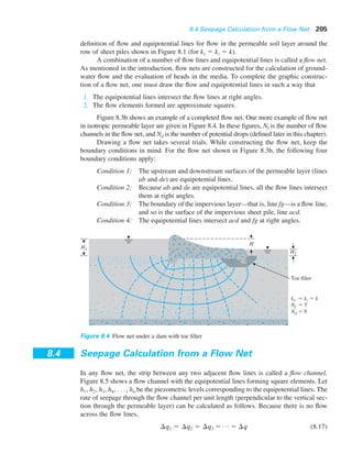
Figure 8.3b shows an example of a completed flow net. One more example of flow net
in isotropic permeable layer are given in Figure 8.4. In these figures, Nf is the number of flow
channels in the flow net, and Nd is the number of potential drops (defined later in this chapter).
Drawing a flow net takes several trials. While constructing the flow net, keep the
boundary conditions in mind. For the flow net shown in Figure 8.3b, the following four
boundary conditions apply:
Condition 1: The upstream and downstream surfaces of the permeable layer (lines
ab and de) are equipotential lines.
Condition 2: Because ab and de are equipotential lines, all the flow lines intersect
them at right angles.
Condition 3: The boundary of the impervious layer—that is, line fg—is a flow line,
and so is the surface of the impervious sheet pile, line acd.
Condition 4: The equipotential lines intersect acd and fg at right angles.
Toe filter
kx ϭ kz ϭ k
Nf ϭ 5
Nd ϭ 9
H1
H2
H
Figure 8.4 Flow net under a dam with toe filter
8.4 Seepage Calculation from a Flow Net
In any flow net, the strip between any two adjacent flow lines is called a flow channel.
Figure 8.5 shows a flow channel with the equipotential lines forming square elements. Let
h1, h2, h3, h4, . . ., hn be the piezometric levels corresponding to the equipotential lines. The
rate of seepage through the flow channel per unit length (perpendicular to the vertical sec-
tion through the permeable layer) can be calculated as follows. Because there is no flow
across the flow lines,
(8.17)¢q1 ϭ ¢q2 ϭ ¢q3 ϭ p ϭ ¢q
2. 206 Chapter 8: Seepage
From Darcy’s law, the flow rate is equal to kiA. Thus, Eq. (8.17) can be written as
(8.18)
Eq. (8.18) shows that if the flow elements are drawn as approximate squares, the drop in
the piezometric level between any two adjacent equipotential lines is the same. This is
called the potential drop. Thus,
(8.19)
and
(8.20)
In Figure 8.3b, for any flow channel, H ϭ H1 Ϫ H2 and Nd ϭ 6.
If the number of flow channels in a flow net is equal to Nf , the total rate of flow
through all the channels per unit length can be given by
(8.21)
Although drawing square elements for a flow net is convenient, it is not always nec-
essary. Alternatively, one can draw a rectangular mesh for a flow channel, as shown in
Figure 8.6, provided that the width-to-length ratios for all the rectangular elements in the
flow net are the same. In this case, Eq. (8.18) for rate of flow through the channel can be
modified to
(8.22)
If b1/l1 ϭ b2/l2 ϭ b3/l3 n (i.e., the elements are not square), Eqs. (8.20) and
(8.21) can be modified to
(8.23)¢q ϭ kHa
n
Nd
b
ϭ p ϭ
¢q ϭ ka
h1 Ϫ h2
l1
bb1 ϭ ka
h2 Ϫ h3
l2
bb2 ϭ ka
h3 Ϫ h4
l3
bb3 ϭ p
q ϭ k
HNf
Nd
Nd ϭ number of potential drops
where H ϭ head difference between the upstream and downstream sides
¢q ϭ k
H
Nd
h1 Ϫ h2 ϭ h2 Ϫ h3 ϭ h3 Ϫ h4 ϭ p ϭ
H
Nd
¢q ϭ ka
h1 Ϫ h2
l1
bl1 ϭ ka
h2 Ϫ h3
l2
bl2 ϭ ka
h3 Ϫ h4
l3
bl3 ϭ p
h1
h2
h3 h4
⌬q
l3
l2
l1
⌬q
⌬q2
⌬q3
⌬q1
l3
l2
l1
Figure 8.5 Seepage through a flow
channel with square elements
3. 8.4 Seepage Calculation from a Flow Net 207
h1
h2
h3 h4
⌬q
l3
l2
l1
⌬q
⌬q2
⌬q3
⌬q1
b3
b2
b1
Figure 8.6 Seepage through a flow
channel with rectangular elements
and
(8.24)
Figure 8.7 shows a flow net for seepage around a single row of sheet piles. Note that
flow channels 1 and 2 have square elements. Hence, the rate of flow through these two
channels can be obtained from Eq. (8.20):
However, flow channel 3 has rectangular elements. These elements have a width-to-length
ratio of about 0.38; hence, from Eq. (8.23)
¢q3 ϭ
k
Nd
H10.382
¢q1 ϩ ¢q2 ϭ
k
Nd
H ϩ
k
Nd
H ϭ
2kH
Nd
q ϭ kHa
Nf
Nd
bn
Impervious layer
Water level
Water table
5 m
Flow channel 1 ϭ 1
l
b
Flow channel 2 ϭ 1
l
b
Ground surface
Scale
Flow channel 3
l
b
1
0.38
Ϸ
5.6 m
2.2 m
a 4.1 m
d c
H
e
b
Figure 8.7 Flow net for seepage around a single row of sheet piles
4. So, the total rate of seepage can be given as
(8.25)q ϭ ¢q1 ϩ ¢q2 ϩ ¢q3 ϭ 2.38
kH
Nd
Example 8.2
A flow net for flow around a single row of sheet piles in a permeable soil layer is shown
in Figure 8.7. Given that kx ϭ kz ϭ k ϭ 5 ϫ 10Ϫ3
cm/sec, determine
a. How high (above the ground surface) the water will rise if piezometers are
placed at points a and b.
b. The total rate of seepage through the permeable layer per unit length
c. The approximate average hydraulic gradient at c.
Solution
Part a
From Figure 8.7, we have Nd ϭ 6, H1 ϭ 5.6 m, and H2 ϭ 2.2 m. So the head loss of
each potential drop is
At point a, we have gone through one potential drop. So the water in the piezome-
ter will rise to an elevation of
(5.6 Ϫ 0.567) ϭ 5.033 m above the ground surface
At point b, we have five potential drops. So the water in the piezometer will rise
to an elevation of
[5.6 Ϫ (5)(0.567)] ϭ 2.765 m above the ground surface
Part b
From Eq. (8.25),
Part c
The average hydraulic gradient at c can be given as
(Note: The average length of flow has been scaled.) ■
i ϭ
head loss
average length of flow between d and e
ϭ
¢H
¢L
ϭ
0.567m
4.1m
ϭ 0.138
ϭ 6.74 ϫ 10Ϫ5
m3
/sec/m
q ϭ 2.38
k1H1 Ϫ H2 2
Nd
ϭ
12.38215 ϫ 10Ϫ5
m/sec215.6 Ϫ 2.22
6
¢H ϭ
H1 Ϫ H2
Nd
ϭ
5.6 Ϫ 2.2
6
ϭ 0.567m
208 Chapter 8: Seepage