6 weeks vocational traning report about dlw varanasi
•
15 j'aime•3,522 vues

This document provides details about Abhishek Priyadarshi's industrial vocational training at Diesel Locomotive Works (DLW) in Varanasi from May 20 to June 30, 2016. It includes certificates of completion, acknowledgments, an introduction to DLW which manufactures diesel-electric locomotives, and summaries of the manufacturing processes and training shops visited including Engine, Block, Loco, High Mast, Heavy Weld, Electrical, Heavy Turning, and Light Assembly shops. The training report aims to share the practical knowledge and experience gained during the vocational training period at DLW.

Recommandé
Contenu connexe
Tendances
Tendances (20)
En vedette
En vedette (18)
Similaire à 6 weeks vocational traning report about dlw varanasi
Similaire à 6 weeks vocational traning report about dlw varanasi (20)
Dernier
Dernier (20)
6 weeks vocational traning report about dlw varanasi
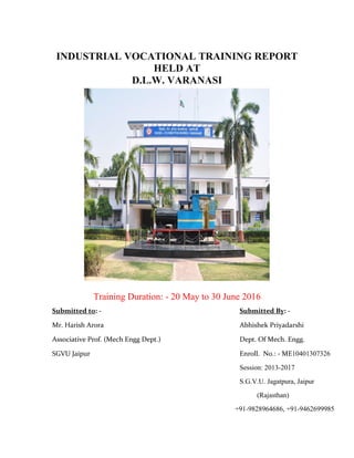
- 1. INDUSTRIAL VOCATIONAL TRAINING REPORT HELD AT D.L.W. VARANASI Training Duration: - 20 May to 30 June 2016 Submitted to: - Submitted By: - Mr. Harish Arora Abhishek Priyadarshi Associative Prof. (Mech Engg Dept.) Dept. Of Mech. Engg. SGVU Jaipur Enroll. No.: - ME10401307326 Session: 2013-2017 S.G.V.U. Jagatpura, Jaipur (Rajasthan) +91-9828964686, +91-9462699985
- 2. 1 CERTIFICATE This is to certify that Mr. Abhishek Priyadarshi, son of Satish Prasad Bachelor of MECHANICAL ENGINEERING (B. tech ME. Engg), has completed summer training from D.L.W. Varanasi as partial fulfillment of Bachelor of Engineering Mechanical. The summer training report and presentation by him is genuine work done by him and the same is being submitted for evaluation. Signature Mr. Harish Arora In charge of Industrial Training & Seminar Department of ME Engg, SGVU
- 3. 2 TRAINING DURATION 20 MAY 2016 TO 30 JUNE 2016
- 4. 3 ACKNOWLEDMENT I would sincerely like to thank the employees and the officers of DLW, VARANASI for their help and support during the vocational training. Despite their busy schedules, they took time out for us and explained to us the various aspects of the working of the plant from the production shops. I would sincerely like to thank Dr. Bipin Kumar Srivastava (Assistant Mechanical Engineer), Mr. Pawan Kumar Srivastava (Training Officer) and Mr. R. R. Mishra (Chief Workshop Instructor/Weld), who was instrumental in arranging the vocational training at DLW Varanasi, and without whose help and guidance the training could not have materialize. I express my deep sense of gratitude to Mr. Vivek Acharya (Principal, TTC) for given me such a great opportunity.
- 5. 4 PREFACE The objectives of the practical training are to learn something about industries practically and to be familiar with the working style of a technical person to adjust simply according to the industrial environment. It is rightly said practical life is far away from theoretical one. We learn in class room can give the practical exposer real life experience no doubt they help in improving the personality of the student, but the practical exposure in the field will help the student in long run of life and will be able to implement the theoretical knowledge. As a part of academic syllabus of four year degree course in Mechanical Engineering, every student is required to undergo a practical training. I am student of Final year mechanical and this report is written on the basis of practical knowledge acquired by me during the period of practical training taken at Diesel Locomotive Works, Varanasi. This report is presented in very simple & understanding on the basis of Primary & Secondary Data.
- 7. 6 DECLARATION I Abhsiehk priyadarshi, Enrollment No-ME10401307326, student of B.Tech.(Mech. Engg.) 4th year of Suresh Gyan Vihar University, Jaipur hereby declare that my project report on “ DIESEL LOCOMOTIVE WORKS ” is an original and authenticated word done by me. I further declare that it has not been submitted elsewhere by any person in any of the institutes for the degree of bachelors of technology. ABHISHEK PRIYADARSHI MECH. ENGG. (4TH YEAR) SESSION:-2013-2017 ME10401307326 SGVU, JAIPUR +91-9828964686, +91-9462699985
- 8. 7 VISION & MISSION Our Vision-”To be a world class manufacturer of Diesel -Electric Locomotives." Our Mission: -"We shall achieve our vision through Continuous Improvement in the areas of Product Quality, Research and Development, Supplier Partnership, Human Resource Development and Team Work with emphasis on Core Competence leading to Customer Satisfaction and Business Excellence."
- 9. 8 TABLE OF CONTENTS 1. Certificate -------------------------------------------01 2. Training Duration -------------------------------------02 3. Acknowledgment -------------------------------------03 4. Preface -------------------------------------------------04 5. Certificate Of Training -------------------------------05 6. Declaration -------------------------------------------06 7. Vision & Mission -------------------------------------07 8. Introduction of D.L.W. -------------------------------09 9. Product -------------------------------------------------13 EMD WDP4 WDP5 10. MANUFACRTING PROCESS -------------25 BLOCK DIVISION ENGINE DIVISION LOCO DIVISION 11. TRAINING SHOP’S -------------------------28 H.M.S -------------------------------------------29 H.W.S -------------------------------------------38 E.E.S -------------------------------------------46 H.T.S -------------------------------------------57 L.A.S -------------------------------------------60 L.T.S -------------------------------------------65 12. LEARNING EXPERIENCE -------------------66 13. BIBLIOGRAPHY -------------------------------68
- 10. 9 INTRODUCTION OF DLW Background Diesel Locomotive Works (DLW) is production unit under the ministry of railways. This was setup in collaboration with American locomotive company (ALCO) USA in 1961 and the first locomotive was rolled out in 1964. This unit produces diesel electric locomotives and DG sets for Indian railways and other customers in India and Abroad. Subsequently a contract for transfer of technology of 4000 HP Microprocessor Controlled AC/AC Freight (GT 46 MAC) / passenger (GT 46 PAC) locomotives and family of 710 engines has been signed with electro motive division of general motors of USA for manufacture in DLW. The production of these locomotives has now started and thus DLW is the only manufacturers of Diesel Electric Locomotives with both ALCO and General motors technologies in the world. Brief History • Set up in 1961 as a green-field project in technical collaboration with ALCO/USA to Manufacture Diesel Electric Locomotives. • First locomotive rolled out and dedicated to nation in January, 1964. • Transfer-of-Technology agreement signed with General Motors/USA in October, 95 to manufacture state-of-the-art high traction AC-AC diesel locomotives. • A flagship company of Indian Railways offering complete range of flanking products in its area of operation. • State-of-the art Design and Manufacturing facility to manufacture more than 150 locomotives per annum with wide range of related products viz. components and sub-assemblies. • Unbeatable trail-blazing track record in providing cost-effective, eco-friendly and reliable solutions to ever-increasing transportation needs for over three decades. • Fully geared to meet specific transportation needs by putting Price-Value- Technology equation perfectly right. • A large base of delighted customers among many countries viz. Sri Lanka, Malaysia, Vietnam, Bangladesh, Tanzania to name a few, bearing testimony to product leadership in its category.
- 11. 10 SALIENT FEATURES:- Annual production capacity 325 Locomotives Annual turn-over (Rs) 3000 Cr. Total number of staff 9225 Workshop land 105 Hectares Township area 211 Hectares Covered area in shops 90300 Sq.m Covered area of other service buildings 75700 Sq.m Electrical power requirement 7596 KVA (Average maximum demand) Electrical energy consumption (units/year) 105.5 million Standby power generation capacity 6300 KW
- 12. 11 IDENTIFICATION OF LOCOMOTIVE Following types of diesel loco are being produced in the DLW:- 1. WDM- Wide Diesel Mixed 2. WDP- Wide Diesel Passenger 3. WDG- Wide Diesel Goods 4. WDS- Wide Diesel Shutter The First Letter (Gauge) 1. W- Indian broad gauge (The “W” stand for wide Gauge-5ft) 2. Y- Meter gauge (The “Y” stands for Yard gauge-3ft) 3. Z- Narrow gauge (2ft 6 inch) 4. N- Narrow gauge (2ft) The Second Letter (Motive Power) 1. D- Diesel 2. C -DC Electric (can run under DC traction only) 3. A- AC Electric (can run under AC traction only) 4. CA- Both DC & AC (can run under both AC & DC tractions) 5. B- Battery Electric locomotive (rare) The Third Letter (Job Type) 1. G- Goods 2. P- Passenger 3. M- Mixed, both goods & passenger 4. S- Shunting (also known as switching engines) 5. U- Electric multiple units (used as commuters in city suburbs) 6. R-Rail cars
- 13. 12 Ex- “WDM3A” “W”-broad gauge “D”- diesel motive “M”- suitable for mixed services “3A”- the locomotive power is 3100HP Or “WAP5” “W”- broad gauge “A”- Ac electric traction motive power “P”- suitable for passenger “5”- denote that this locomotive is chronologically the 5th electric locomotive model used by the railway for passenger. Types of WDM26 & WDP2 engine respectively
- 14. 13 Products DLW is an integrated plant and its manufacturing facilities are flexible in nature. These can be utilized for manufacture of different design of locomotives of various gauges suiting customer requirements and other products. The product range available is as under. WDG4 4000 HP AC/AC Freight traffic Locomotive WDP4 4000 HPAC/AC Broad Gauge High Speed Locomotive WDG3D 3400 HP AC/AC Broad Gauge Mixed Traffic Micro-Processor Controlled Locomotive. WDM3C 3300 HP AC/DC Broad Broad Gauge Mixed Traffic Locomotive. WDM3A 3100 HP AC/DC Broad Gauge Mixed Traffic Locomotive. WDP3A 3100 HP AC/DC Broad Gauge High Speed Passenger Locomotive. WDG3A 3100 HP AC/DC Broad Gauge Freight Locomotive. WDM2 2600 HP AC/DC Broad Gauge Mixed Traffic Locomotive. WDP1 2300 HP AC/DC Broad Gauge Intercity Express Locomotive. WDM7 2150 HP DC/DC Broad Gauge Mixed Traffic Locomotive. WDM6 1350 HP DC/DC Broad Gauge Mixed Traffic Locomotive. WDS6 1350 HP AC/DC & DC/DC Broad Gauge Shunting Locomotive. YDM4 1350 HP AC/DC & DC/DC Broad Gauge Mixed traffic Locomotive. EXPORT LOCO 2300 HP AC/DC Meter Gauge/Cape gauge Mixed Traffic Locomotive. Diesel Generating Sets 800 KW to 2500 KW Spare Parts for engines, locomotives and generating sets
- 15. 14 EMD(Electro Motive Division Shop) WDG-4000 HP GOODS LOCOMOTIVE Broad Gauge freight traffic Co-Co diesel electric locomotive with 16 Cylinder 4000 HP, AC-AC transmission, microprocessor control population and braking with high traction high speed cast steel trucks. First turned out in 1999 with transfer of technology from General Motor (USA), this locomotive has exceptional fuel efficiency and very low maintenance requirements. It is specifically designed for heavy haul freight traffic requirements of Indian Railways for the 21st Century. The heart of loco Traction Control Converter uses the GTO devices (obsolete technology). Now the IGBT devices, has been introduced from Oct. 2006. It is the latest technology and will be cost effective and gives higher reliability. The locomotive power has been upgraded to 4500 BCV and the first Loco (Loco No 12114) was manufactured in May 07. General Characteristic Installed Power Axle Load Gauge Wheel arrangement Wheel diameter Height Width Overall Length (Over Buffer Beam) Weight Max tractive effort Maximum speed Fuel tank capacity Locomotive Control 400HP 21T 1676mm Co-Co 1092mm 4201mm 3127mm 19964mm 126T 54T 100Km/h 6000lts EM 2000 with SIBAS-16 Traction Control
- 16. 15 WDP4-4000 HP PASSENGER LOCMOTIVE State-of-Art, Microprocessor controlled AC-AC, Passenger Locomotive Powered with 16-710G3B 4000HP Turbo charged two stroke Engine. Fabricated rigid design under frame, two stage suspension, and High Traction High Speed 3 axle (HTSC) light weight cast truck frame attribute to high adhesion performance. First turned out in 2003, this locomotive has exceptional fuel efficiency and very low maintenance requirements. It is specifically designed for heavy haul passenger traffic requirements for Indian Railways. The WDP4 fleet is being upgraded by provision of hotel load feature along with power up gradation to 4500 HP. The prototype will be manufactured in the year 2007. Diesel Engine Transmission 16 Cylinder 710 G3B, 2 stroke, turbocharged after cooled Fuel Efficient Engine Injection System Direct Unit Injector Governor Woodward Compression Ratio- 16:1 Lube Oil Sump Capacity 1073 Lts Electrical AC-AC 4 Traction motor ( 3 in parallel per bogie) Suspension Axle hung / taper roller bearing Gear Ratio 77:17
- 17. 16 This is the type of WDP4D engine.
- 18. 17 WDG-5000HP LATEST LOCOMOTIVE A new diesel locomotive for Indian Railways - the WDG5 These are the first images of # 50001, the prototype WDG5 locomotive at DLW, Varanasi. At 5,500 HP, this is the most powerful diesel locomotive to be ever made in India. The locomotive is ready, except for the RRT (Real Road Test) clearance from CRS. The locomotive or the series is named Bheem, after the strong Pandav brother from epic of Mahabharat. The loco has a 20 cylinder EMD prime mover and an AC-AC transmission. WDG5 from the long hood end. The cooling duct that obstructed vision towards the long hood on a WDG4/WDP4 is missing in this loco. The modification could improve long hood operations, despite the extra length of the WDG5.
- 19. 18 LINE DIAGRAM OF DIESEL LOCMOTIVE Main Alternator:- The diesel engine drives the main alternator which provides the power to move the train. The alternator generates AC electricity which is used to provide power for the traction motors mounted on the truck (bogie). In older locomotives, the alternator was a DC machine, called a generator. It produced direct current which was used to provide power for DC traction motors. Many of them machines are still in regular use. The next development was the replacement of the generator by the alternator but still using DC traction motors. AC output is rectified is give the DC required for the motors. Auxiliary Alternator: Locomotive used to operate passenger trains with an auxiliary alternator. This provides AC power for lightening, heating, air conditioning, dining facilities etc. on train .The output is transmitted along the train through an auxiliary power line.
- 20. 19 MOTOR BLOWER:- The diesel engine also drives a motor blower. As its name suggests. The motor blower provides the air which is blown over the traction motors to keep them cool during period of heavy work. The blower is mounted inside the locomotive body but the motors are on the trucks, so the blower output is connected to each of the motors through flexible ducting. The blower output blower also cools the alternators. Some designs have separate blowers for the group of motors on each truck and others for the alternators. Whatever the arrangement, a modern locomotive has a complex air management system which stem which monitors the temperature of the various rotating machines in the locomotive and adjust the flow of air accordingly. AIR INTAKE:- The air for cooling, the locomotives motors is drawn in from outside the locomotive. It has to be filtered to remove dust and other impurities and its flow regulated by temperature, both sides and of the locomotive. The air temperature system has to take account of the wide range of temperatures from possible +40°C of summer and to the possible -40°C of winter.
- 21. 20 ELECTRONIC CONTROLEE: - Almost every part of the m art of the modern locomotive equipment has some of electronic control. These are usually collected elected in a control cubicle near the cab for easy elected in a control cubicle near the cab for easy access. Cab:- The standard configuration of US-designed locomotive is to have a cab at one end of the locomotive only.
- 22. 21 Batteries:- Just like automobile, the diesel engine needs a battery to start it and to provide electrical power for the lights and controls when the engine is switched off and the alternator is not running. PINION/GEAR:- The traction motor drives the axles through a reduction gear of a range between 3 to1 (freight) and 4 to 1 (passenger). Gear box:- The radiator and its cooling fan are often located in the roof of the locomotive. Drive to the fan is therefore through a gearbox to change the direction of the drive upwards.
- 23. 22 Traction motor:- Since the diesel-locomotive uses electric transmission, traction motors are provided on the axles to give the final drive. These motors were traditionally DC but the development of the modern power and control electronics has led to the introduction of 3FAC motors. Traction Motor Fuel tank:- A diesel locomotive has to carry its own fuel around with it and there has to be enough for a reasonable length of trip. The fuel tank is normally under the loco frame and will have a capacity of say 1000 imperial gallons .the new AC 6000s have 5500 gallon tanks .In addition to fuel , the locomotive will carry around , typically about 300US gallon of cooling water and 250 gallon of lubrication oil for the diesel engine.
- 24. 23 Air compressor:- The air compressor is required to provide a constant supply of compressed air for the locomotive and train brakes. Drive shaft:- The main output from the diesel engine is transmitted by the drive shaft to the alternators at one end and the radiator fans and compressor at the other end. Turbo charger:- The amount of the power obtained from a cylinder in a diesel engine depends on how much fuel can be burn it in. the amount of fuel which can be burnt depends on the amount of air available in the cylinder. So turbocharger is used to increase the amount of air pushed into each cylinder. The turbocharger is driven by exhaust gas from the engine. This gas drives a fan which in turn, drives a small compressor which pushes the additional air into the cylinder. The turbocharging gives a 50% increase in engine power.
- 25. 24 Sand box:- Locomotives always carry sand to assist adhesion in bad rail conditions. Truck frame:- This is part (called the bogie in the UK) carrying the wheels and traction motors of the locomotive.
- 26. 25 MANUFACTURING PROCESS PRODUCTION SHOPS:- Production shops are divided in three Divisions:- 1. BLOCK DIVISION 2. ENGINE DIVISION 3. LOCO DIVISION BLOCK DIVISION:- 1. Heavy Weld shop 2. Heavy Machine Shop ENGINE DIVISION:- 1. Engine Erection Shop 2. Engine Testing Shop 3. Light Machine Shop 4. Sub Assembly Shop 5. Rotor Shop 6. Heat Treatment Shop LOCO DIVISION:- 1. Loco Frame Shop 2. Pipe Shop 3. Truck Machine Shop 4. Traction Assembly Shop 5. Sheet Metal Shop 6. Loco Assembly Shop 7. Loco Paint Shop 8. Loco Test Shop
- 27. 26 SERVICE SHOP:- 1. Maintenance Area#1, 2, 3 2. Tool Room 3. Central Transport Shop PERSONNAL DEPARTMENT:- Prepare payment of Staff, Leave Record, Personal Record of every Employee, Housing allotment, Welfare of Staff Etc. HEALTH DEPARTMENT:- Having facility of Indoor & Outdoor patients. CIVIL DEPARTMENT:- Maintenance of colony quarters, up gradation of facilities in quarters, sanitation. ELECTRICAL DEPARTMENT:- Maintenance of Lighting in quarters and in workshop, electrical work in locomotive Etc. TECHNICAL TRAINING CENTER:- Provide training to all employees at time to time to refresh update their knowledge. RESEARCH & DEVELOPMENT:- 1. R & D – A Customer centric Activity Committed to innovation and Continuous Improvement. 2. Highly skilled manpower capable of handling complete R&D activities. 3. A sophisticated design centre with modern CAD/CAE workstations equipped with Unigraphics and Ansys. 4. Back-up support from RDSO, a centralized R&D organization at corporate level. 5. Several milestones in the past – an enviable pedigree viz. a) Original ALCO design made 7% more fuel efficient. b) Many design improvements leading to better performance, incorporated in the original ALCO design.
- 28. 27 c) Many new design for locomotives such as WdP1, WDG2, WDP2, WDP4, WDP5 to name a few. RECENT MILESTONES & FUTURE PLAN:- MILESTONES ACHIVED: - Transfer of technology (TOT) – An added feature in the cap:- Agreement with General Motor of USA for technology transfer to manufacture high horse-power GT46MAC 4000HP & WDG-5 5000HP AC/AC locomotive in India. Only country outside North-America to have this bleeding edge technology many export/repeat orders complied successfully in recent past and many more in the pipeline, Supplied more than 400 locomotives to various non-railway customers. Emerging as a leading manufacturer of ALCO/GM locomotives for developing countries. FUTURE PLANS:- Assimilation of GM technology to manufacturing their latest 710 series of diesel electric locomotives. To emerge as a globally competitive locomotive manufacturer. To develop as an export hub for ALCO/GM locos for Asian market. To follow an export led growth strategy through continuous improvement. Cost effective and technology/product up-gradation as a key to retain global competitiveness by pitting price-value-technology equation right.
- 30. 29 HEAVY MACHINE SHOP This shop carries out the machining of Cyl. BLOCK (M.G. & B.G.) main base, saddler Main bearing caps, Splines, Turbo Super Charger, Lube Oil, Fuel Oil & Water header) com bearing housing. OPERATION:- Planning, Milling, Drilling, Tapping, Boring Honing, Angular Boring, Serration milling etc. Types of Machine provided in the shop are:- Double Housing planned machine (32”, 24’, & 16’). Radial drilling machine. Radial drilling machine Traveling type. Boring Machine Angular Boring Machine (Excello) Tracer Planner machine. Hill Acme doing structural milling machine TOOLS USE:- 1. O.K. Tool (Rough & Finish) 2. C.C. Milling cutter (4”, 9”, & 10”) 3. Boring Tipped Tool (Rough & Finish) 4. Honing Stone (For hand honing) 5. Drill, Reamer, Top (Various Seizer) 6. Serration Cutter.
- 31. 30 MEASURING INSTRUMENT 1. Dial Bar gauge 2. Micron meter (outside and depth) 3. Vernier Height gauge. 4. Vernier callipers 5. Mandrill or optical shad rill machine BLOCKS EX-CELLO ANGULAR BORING MACHINE:- Motor R.P.M. in constant, Spindle, speed is control by clutch system.
- 32. 31 H.M.T. ANGULAR BORING MACHINE:- Spindle speed is directly controlled through motor. (Coated carbide is used in H.M.T. angular Boring machine) Cyl. Block made of fabricated class II material except main bearing cop as it made class IV material. The machining of Cyl. Block is complicated and challenging job. It required great skill and knowledge. After duly fabricated, stress relieved and shot blasted the block is subjected to layout to ensure availability of adequate machining allowance, where necessary and to provide guide liner for subsequent machining the weight of the block is 6.02 Tons approx. (Fabricated Material) After completion of all operations as per drawings the black subjected to inspection in addition to stage inspection dimension live radial distance between centre of Crank bore and com bore, distance between centre of com bore and liner seat etc. are checked at this stage the weight of the black is 05.02 tons approx. 01 ton of material removed by the machining and then blank is block send for assembly. Angular Boring Machine Angular boring "V" boring is done of special purpose machine which is a special purpose machine, which has two high precision angular boring bars on which different boring inserts are mounted. The cutting inserts on boring bars to achieve evenly distributed cutting load during boring operation. This contributes to accuracy while machining. Boring bars are mounted on high precision bearings which provide control on size during angular boring. The machine is capable of boring and drilling to different size.
- 33. 32 Angular Boring of G.M. Block Method: - Load the block on fixture. For checking whether there is any gap or not put the filler of the size 0.001” to 0.0015” in side location pad. If there is no gap then start work otherwise tight the fixture and recheck till no gap situated. Boring of Top deck Bore: Tool:- There are 18 tools are used. I tool in each side. Each are adjusted automatically for rough cut and finish cut. During rough cut, finish tool remains idle and during finish cut, rough tool remains idle. 7 tools are fixed in each side in boring bar and two are replaced according to demand of boring.
- 34. 33 Different tools which are used are as follows:- 1. M.I.D. Counter Insert No – TPUN – 160308 2. Rough – snmm – 190612 (weight) 190616 (yellow) 3. Liner seat rough TNMG 220412 4. T/D Chamfer P.G. 002 (only for 1263 m/c) 5. Liner seat finish – TPUN – 110308 6. Micro boring tool OOC No. 10A2LB 7. Counter insert wide no. – PNUN – 160402 8. T.I.D. Counter No. (Rough) – 1263 (N.C.)TN – 28 (TNUN 220 412) 9. 2187 M/c. – MIS Counter No. TNMM – 160408 Horizontal Boring Machine:- MW :- (no): 2155 & mw No. : - 2154 Cam and Crank. Boring of cylinder block crank and cam. Method:- Load the block on fixture. For checking whether there is any gap Or not put the filler of size 0.001” to 0.0015” in side location pad. If there is No gap then start work otherwise tight The fixture and recheck till no gap situation. Boring of Cam Bore: (LS & RS):- This is done in three steps: (a) Rough Bore: - Do this in one pass R.P.M.: 35 Feed: 6 mm/min.
- 35. 34 (b) Semi Finish Boring: - Do this in one pass R.P.M.: 35 Feed: 6 mm/min. (c) Finish Boring: - Do this in one pass Pass No. Bore No. R.P.M. Feed 1. 1, 4, 7, 10 2. 2, 5, 8, 224 25mm/min 3. 3.6.9. Boring of Crank Bore: This is also in three steep. (a) Rough Boring: Do this in three pass. Pass No. Bore No. R.P.M. Feed 1. 1, 4, 7, 14 5 mm/min 2. 2, 5, 8, 3. 3, 6, 9 (b) Semi Finish Boring: Do in one pass R. P. M.: 14 Feed: 5 mm/min (c) Finish Boring: Do in one pass R. P. M.: 140 Feed: 25 mm/min Tool:- Two tools are used for boring both tools are fixed in slot of boring bar. Due to spindle rotation boring is done. Tool movement and machine action is governed by G Code and M Code respectively. Absolute mode and incremental modes are used for tool movement. Single point cutting tool (two) is first fitted in devise block then in boring bar.
- 36. 35 Cutting Oil: - Boring finishing operation cutting oil is used for smooth operation Fixture: J/F No. : FB (E) 15/2 Different – Different tools are used in different step of Boring! Crank:- Rough Boring : 8.880” Semi Finish Boring : 8-997” Finish Boring : 9.035” Cam: Rough Boring : 4.700” Semi Finish Boring : 4.720” Finish Boring : 4.750” Maximum removal of metal takes place in rough boring. For making thrust (Cutting) Tool Size : 10” R.P.M. : 14 Feed : 22.86 mm/min (.09”/min) Tool material used in rough and semi finish boring is high speed steel and in finish boring amended carbide.
- 37. 36 Main dimension of Cyl. Block:- 1. Did of com bore = 4.750” to 4.7515” (B.G. & M.G.) 2. Did of blank bore = 9.0355” to 9.0370” (M.G. & B.G.) 3. Did of liner bore = 10.750” to 10.752” (Upper) (B.G. of M.G.) = 10.621” to 10.623 (Lower) 4. Die of thirst Collar = 10ψ ” 5. Thickness of thrust bearing = 4.247” to 4.249” 6. Thickness of the plate = free end = ” = gen. End = 1ω” 7. Radial distance between the centres of crank of Cam bore = 10.499” to 9.501” 8. Distance of liner seat from centre of crank Bore = 32.480” to 32.485” 9. Total length of the M.G. black = 106.370” = 106.380” 10.Total length of main Bush B.G. = 172.380” B.G. = 172.370” 11.Total length of main Bush M.G. = 117.130” = 117.120” 12.Total length of B.G. Black = 161.625” = 161.630” Main parts of the Cyl. Block (B.G.) 1. Foundation Rail (R.S. AND L.S.) 2. Saddle ( 9 Nos) 3. Spline 4. Inner well (R.S. and L.S.)
- 38. 37 5. Other well (R.S. and L.S.) 6. Top deck (Middle) 7. Top deck (R.S. and L.S.) 8. Side sheet (R.S. and L.S.) 9. Com bearing (16 Nos) 10. Cop (9 Nos.) 11. Rib (16 Nos.) 12. Bottom Deck. Or Middle deck 13. Fuel self-comport. Main parts of the Cyl. Block (M.G.) 1. Foundation Rail (R.S. and L.S.) 2. Saddle – 7 Nos. (One Centre) 3. Top deck 4. Middle deck. 5. Side sheet (R.S. and L.S.) 6. Cam. Bearing 6 Nos. 7. Cap – 7 Nos. 8. Ribs – 10 Nos. 9. Fuel self-comport. 10.Inner wall (R.S. and L.S.)
- 39. 38 HEAVY WELDING SHOP (H.W.S.):- In the DLW there are basically three type of welding used in HWS. The welding quality of DLW is very high quality. After the machining process we can’t say that this piece is no single piece. 1. Submerged arc welding 2. Manual metal arc welding 3. MIG welding SUBMERGED ARC WELDING:- In submerged arc welding the welding process will be covered with the flux so that it will not react with oxygen and nitrogen. Because of the versatility of the process and the simplicity of its equipment and operation, shielded metal arc welding is one of the world's most popular welding processes. It dominates other welding processes in the maintenance and repair industry, and though flux-cored arc welding is growing in popularity, SMAW continues to be used extensively in the construction of steel structures and in industrial fabrication. The process is used primarily to weld iron and steels (including stainless steel) but aluminum, nickel and copper alloys can also be welded with this method.
- 40. 39 SUBMERGED ARC WELDING GMAW WELDING GMAW COMPONENTS: - 1. DC or Direct Current power supply 2. Electrode or wire feed controller 3. Wire drive roller assembly 4. Shielding gas source (cylinder) & regulator 5. Manually held Gun & ground clamps 6. Wire reel
- 41. 40 MIG WELDING:- MIG welding can be used for most types of metals; steel, stainless steel, as well as aluminum. But welding aluminum is very different from welding mild steel because aluminum is a metal that is different from steel. So when we weld aluminum, we have to use other parameters, other settings. Aluminum has a lower melting temperature than mild steel, for example, so you should expect that we should use a lower heat input but in spite of this. So we have to use a higher local heat-input but a faster welding speed than with steel to get good fusion and penetration. This sounds as if aluminum welding is difficult, but it's not. The welding sets that we use adjust the welding parameters automatically, so the welder can concentrate on the welding operation, the movement of the welding gun and the weld pool.
- 42. 41 This shop mainly deals with the fabrication of the engine block and base (B.G. & M.G.) Turbo support. After cooler housing items. The engine block is the principal, structural member of the diesel engine. It is composite weldment with heavy plates thickness varying from 16 mm to 75 mm and steel forgives on forming to specification is 2062. The spine being the most highly stressed item as we can say spine of the cylinder block is made out of one piece bitted 5x 7 thickness confirming to be 1895. The billet foundation plate and cylinder walls are built around the steel forging saddles to form the air chambers which ensure the maximum rigidity for successful fabrication of cylinder block special attention is paid to the following aspects cylinder block special attention is paid to the following aspects. 1. Inspection standard 2. Proper materials 3. Proper electrodes and flux 4. Proper welding technique 5. Welfare of staff
- 43. 42 SEQUENE OF FABRICATION OF ENGINE BLOCK 1. Set up of saddles foundation plates and spine on special fixture and weld saddles spine founded on rails. 2. Set up welding of outside cylinder wall. 3. Set up of middle dock (Tack welded) with respect to target. 4. Remove can bearing shim from saddle face. 5. Intermediate machining operation remark in middle deck and chamber at top of spline. 6. Set up of inside wall and deck welded with spline. 7. Lay out of plane height. 8. Intermediate machining operation Machine height of outside wall and inside wall with respect to marking and camber. 9. Set up of top deck (Both side) and lifter block (G.E. side only) for filament of eye bolt and tack weld. 10.All in side (8x2 Beal welds) welding in done by sub are method. 11.Back gauging of saddle to foundation rail joint. 12.Lay out for bearing. 13.Set up for cam bearing with respect to pay out Si No.12. 14.Welding of the cam bearing and saddle with foundation rail bottom side (back gauge portion). 15.Set up of cam bearing rids and weld. 16.Say out for 8 machining. 17.Intermediate machining operation. 18.Flame cut counter of foundation plate to give relief clearance to free movement of counter with respect to crank shaft. 19.Set up of the side sheets and sub arc weld of side sheets and top deck. 20.Set up of full control compartment sheet and weld. 21.Intermediate machining operation mills both and to lay out for end plates considering total length and machining allowance. 22.Hydrostatic test of water compartment. 23.Set up of top end plates and weld. 24.Set up of top deck centre and weld. 25.Stress relieving weldment. 26.Kerosene oil test for control shaft compartment. 27.Shot plast. 28.Final debarring. Note: Saddle outside and inside walls foundation rail are x ray joints.
- 44. 43 ELECTRODE:- Saddle, spline and foundation plates are sledded on a rotary fixture E 6020 electrodes 6.3 mm and 5 mm of M/s A Par Pvt. Ltd. Bombay and celorex of M/s Advani or Liken capable of giving X-Ray quality joints are being used for the welding. The coating is such that a stage containing iron oxide, manganese oxide and silicon is usually produced other constituents containing the oxides of aluminum manganese of sodium are prevent to modify the slag ferromanganese in the main DE oxygen and sodium silicate is used as the binder. In most cases core wire is of remounted steel. FLUX: - D.L.W. auto melt gr I flux of advance linken (P) LTD. Bombay In used. The flux in a mixture of power of determined practical size and each particle in chemically basic in character these particles are not fused. the flux in heated period to use in on over at 250 c for O2 hours as moisture flux generated the hydrogen in the arc and cause cold cracks in the weld deposit and in the heat effected zero. WIRE:- Wire used in the sub are welding is the auto melt gr. A cold copper coated size 5m.m. with low carbon content confirming to IS 2879 Manufactured by M/S Advani lincon P. ltd. Bombay. The chemical composition of the wire in carbon 0.08% mm 0.46% P.0.018% S0.022%. STRESS RELIVE OF CYLINDER BLOCK:- After completion of welding the cylinder block in then stress relieved at the temp. Ranging from 115 F obtaining total timing 28 Hrs. i.e. (1) Pre heat time 14 Hours. (2) Soaking time 04 Hrs. and (3) Cooling time 10 Hrs. In stress relative‘s furnace capable to accommodate to B.G. block at a time. As the engine block in machined to very close tolerances. It is necessary that all stresses developed during the fabrication stages are completely relieved before machining. This would ensure a longer life in service without any distortion which would normally result on account of very alternating stresses that the engine block is subjected to during its service.
- 45. 44 KEROSINE OIL TEST:- Check that there should not be any leakage at the bottom side of the fuel control compartment welding joint after powering kerosene oil. The engine block is then shat blasted at pneumatic compressed air a pressure of 75ibs/sgu. Inch. DEBURING:- It is to be ensured that the completes (welding) weldment is free of any spatter welding defects and sharp corrosion of important welded joint have been ground then the cylinder block is marked and handed over for machining operation to H.M.S. SEQUENCE OF FABRICATION ASSEMBLY:- Setting of saddles on the fixtures as per drawing with the foundation plat L.S. & R.S. and one spine on the top of the saddle. Tacked and welded all these with each other burn run of the saddle with spline, clean and grind the opening of the spline, then set and face the outside and inside walls L.S. & R.S. both sides of the saddle burn run off and clean grind of the wall opening After that setting up the middle deck weld from bed bottom side of deck and lifter block weld 16 beets all welding as quality. Saddle to foundation plate, saddle to spline and saddle to outside wall welding is check as joints. Arc wilding done machine on the cylinder block where the welding by machine is called submerged are welding. Copper coated mild steel class II were with flux is used. After x-ray welding test, the assembly is sent for lay our of cam bearings in marking section. The cambering are set up tack and weld with the cam ribs and water compartment plates. After that again x-ray text of bottom plates is done. Then burn opening and Skelton grinding operation is done. Then send this block assembly in the machine section for 8 machining of side sheet. Set and weld the side sheets on the 8 machining. Weld fuel self-compartment on the positioned welding machine. Weld side sheet foundation rails. Side sheet to cam ribs. Outside wall of full self-compartment. After that the block assembly is again sent to M/C section. For end milling to maintain the length of the block as per marking and size. Then hydraulic water test is done at 75 P.S.I. At last set up the end plates (gen and free end) both side of the block assembly, tack and then setup the top deck center in the center of the block and weld it by sub are welding M/C.
- 46. 45 After complete fabrication the block is sent to H.T.S. sec. for stress reliving to 700 c then shot blasting the block and sent the machine section for final machining. Main base fabrication: - The following components are required for the assembly of main base. 1. Side sheet L.S. and R.H. 2. Pipe assembly with plates 3. Engine mount free end and gen end CH/RH 4. Rib (engine mount free end & engaged) 5. Top rail 6. Bottom. Plate (Gen end, free end & centre) 7. Plug L.O. drain. 8. Cross web G.A. 1,2,3,4,5,6,7,8, & 9 9. Cross web auxiliary assembly 10.End plate free end & gen end 11.Oil drain compartment. 12.Pad 13.Brass engine mount free end. 14.Brass engine mount gen end. 15.L.O. suction pipe (sub. Assembly) WELDING PROCESS:- (1) Outside bottom plate, top plate, centre plate to side plate both sides an rest welding is down from bottom is top in sequence numbest for inside welding bottom pt, top plate and rest, from bantam is tip is done. (2) In this operation the support is clamped on positioned with top plate and all the rest wadding is completed.
- 47. 46 ENGINE ERECTION SHOP Engine erection shop There are seven sections in this shop from 01 to 07 action have two or three station as given below:- Station No. 1 to 4 in section 01 Station No. 5, 6, 6A and 6B are in section 02 to 03 Station No. 7 to 12 are in section 04 to 07 Station No.1 to 4 - Washing, debarring and panting Station No. 5 - Cam shaft bush fitting cylinder head stud driving linear Sleeve and Liner pressing and water testing. Station No. 6A - Piston Assembly. Station No.6B - Crank Shaft Assembly. Station No 6 - Piston Assembly Heads, Exhaust Manifold, water Connection, Air elbows, Nozzle and water header Pipe-fitting. Station No.7 to 9 - Lowering engine block, oil catcher, Generator, Lube Pump and water pump fitting oil. Station No. 10 - Cam shafts, gears, Control shaft, Turbo supper cooler, Oil Seal, Turbo super charger application. Station No.11 & 12 - Fuel pump Support, Valve leaver, Governor Application. Piping (Fuel Pump Support) Fuel oil header, valve gear header, Tubes, High pressure pipes, Lube oil strainer, Spray Nozzle and Governor Pipes application etc.
- 48. 47 Washing:- In this section the M.G. & B.G. Blocks are washing after the welding process is completed. Debarring:- It is to be ensured that the completes (welding) weldment is free of any spatter welding defects and sharp corrosion of important welded joint have been ground then the cylinder block is marked and handed over for machining operation to H.M.S. Panting:- After the washing of M.G. & B.G. Blocks are painting on painting shop. After the assembling of all component on engine & testing of engine the painting process is over on painting shop.
- 49. 48 Engine Painting Piston Assembly
- 50. 49 Piston Assembly Heads, Exhaust Manifold, Air elbows, Nozzle and water header Pipe-fitting. Cam shafts, gears, Control shaft assembly
- 51. 50 Gear application. Valve leaver
- 52. 51 Lowering engine block, oil catcher, Generator, Lube Pump and water pump fitting oil. Fuel pump Support, Valve leaver, Governor Application. Piping (Fuel Pump Support) Fuel oil header, valve gear header, Tubes, High pressure pipes, Lube oil strainer, Spray Nozzle and Governor Pipes application etc.
- 53. 52 Oil Seal, Turbo super char
- 54. 53 Turbo supper cooler
- 55. 54 Tubes, High pressure pipes
- 57. 56 Final Engine:- For Export of Engine & ready for assembly with loco.
- 58. 57 HEAT TREATMENT SHOP In this shop hardening, stress leaving, tempering, normalizing, carburizing, quenching, is done by help of conventional & unconventional process. Here we are doing hardening of cam-shaft, connecting rod, piston pin, different small components of cylinder head. This shop is divided in two parts which are as follows:— 1. Induction Section—Use for Induction hardening 2. Furnace Section—Use for Overall process Induction Section:- In induction section, stress leaving & hardening of cam shaft, its bearing & cam lobes is done at different temperatures. In induction type hardening we are using copper coil for hardening. Stress leaving is done below critical temperature. Cam shaft is made up of alloy steel i.e. we are doing stress leaving process at a temp 723°C. After that hardening is done by induction coil. The major drawback of this process is to decide what the exact temp is for stress leaving or hardening. In induction method copper coils are heated due to this induction current will generate. This induction current produces an electromagnetic force. Which attracts the carbon particles to the surfaces due to this the bond breaking energy is developed & that energy is causes heating of material. At that we can‘t does any arrangement for measuring the temp of work piece. • Hardening—At temp 900°C • Quenching—Water+8 to 10 %polymer quench • Tempering—below critical temp
- 59. 58 Furnace Section:- In this section we are using different type of furnaces for all the heat treatment process will be done. For hardening carbon must be present up to 0.5%.Hardening is done in furnace at 920°C here thermocouple are attach for measure exact temp of hardened material. Furnace section
- 60. 59 Quenching:- Quenching is done after hardening of material. In this air cooling is done. When our job is come at 100°C then other heat treatment process is done. Carburizing:- Carburizing is process for those materials which has low percentage of carbon. Carburizing is done in a special machine. Carburizing is done by two methods first one is Wet & second is Gas. For wet, liquid calcium carbonate is use. Tempering:- Tempering is done below critical temp to release stress between hardened & unhardened zone to increase the life of job. After that we are checking the hardness of job on Brinell Hardness Machine. This is done on gauge room.
- 61. 60 LOCO ASSEMBLY SHOP L.A.S. OPERATION- 1. Drive cap assembly, Air compressor assembly, Control stand assembly. 2. Driver cap checking, Air brake piping. 3. Long hood assembly, Buffer assembly, Radiator setting. 4. Engine setting, Compressor setting. 5. Long hood setting, Auxiliary generator assembly and setting Alternator part packing and assembly. 6. Equipment assembly, Fuel oil parking, Lube oil piping, Engine water cooling piping. 7. Driver sheet setting, Damper assembly, Air, duct setting. Drive cap assembly
- 62. 61 Air compressor assembly Control stand assembly
- 63. 62 Engine setting Compressor setting
- 64. 63 Air brake piping Long hood setting, Auxiliary generator assembly and setting Alternator part packing and assembly
- 65. 64 Air, duct setting
- 66. 65 LOCO TEST SHOP(L.T.S.):- IN THIS SHOP CHECK THE FOLLOWING THING- 1. POT TEST 2. TRAINLINE CONTINUITY 3. BLOWER/FANS OPERATION 4. POWER CONTACTOR OPERATION 5. DYNAMIC BRAKE SIGNALS 6. ENGINE START 7. ENGINE RUN 8. EXCITATION TEST 9. PRELOAD 10.LOAD TEST 11.TRACK TEST 12.PREDILEVERY TEST
- 67. 66 Learning Experience Working on this project was a pleasure for me as I learned lot of things which was unknown to me before doing this project. I worked In, Heavy Machine Shop (HMS), Heavy Weld Shop (HWS), Engine Erection Shop (EES), Heat Treatment Shop (HTS), Loco Assembly Shop (LAS) and Loco Test Shop (LTS) my job description includes regular updating status to know about all related to Production Unit, Diesel Generating sets and their spares for Indian Railways and Non-Railways customer. I tried to give my best effort on this project but it could be better if I would have theoretical knowledge about workshops before taking this project. As this topic was new to me and due to time constraint I was not able to through each and every Procedure.