Logic gates
•Télécharger en tant que PPTX, PDF•
0 j'aime•660 vues

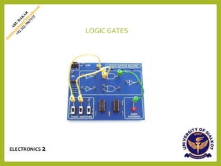
Logic gates are the basic building blocks of any digital system. It is an electronic circuit having one or more than one input and only one output. The relationship between the input and the output is based on a certain logic. Based on this, logic gates are named as AND gate, OR gate, NOT gate etc.

Recommandé
Contenu connexe
Tendances
Tendances (20)
Similaire à Logic gates
Similaire à Logic gates (20)
Plus de THE CREATORS ACADEMY
Plus de THE CREATORS ACADEMY (20)
Dernier
Dernier (20)
Logic gates
- 2. ABOUT ME CONTACT INFO Tel: (+92) 322 7967172 E-Mail: abubakarmehmood786@yahoo.com SKILLS & LANGUAGE ORIGIN LAB, VIRTUAL LAB, ENDNOTE SOFTWARE, EMATHHELP SOFTWARE , MICROSOFT OFFICE, ADBOBE (PHOTOSHOP & ILUUSTRATOR), ARDUINO SOFTWARE, AMAZON VITUAL ASSISTAN, VIDEO EDITTING, SOCIAL MEDIA ACCOUNT MANAGEMENT URDU, PUNJABI, ENGLISH, ARABIC FOUNDER UCQxAo-GBHUI2l9_LBYicsRw THE CREATOR ACADEMY thecreatorsacademyofficial thecreatorsacademyofficial The Creators Academy ABU BAKAR NATIONALITY : PAKISTAN CITY : SIALKOT, PUNJAB MARITAL STATUS : SINGLE PERSONAL PROFILE BS(HONS) PHYSICS UNIVERSITY OF SIALKOT EDUCATION SOCIAL MEDIA Abubakar Bhutta @_abubakar786 ABU BAKAR @abubakar786786 ABUBAKAR692909
- 3. CONTENTS o History o Definition o The OR gate o The AND gate o The NOT gate o The NAND gate o The NOR gate o The XOR gate o The XNOR gate o Applications
- 4. HISTORY The binary number system was refined by Gottfried Wilhelm Leibniz (published in 1705). In an 1886 letter, Charles Sanders Peirce described how logical operations could be carried out by electrical switching circuits.
- 5. INTRODUCTION Logic gates perform basic logical functions and are the fundamental building blocks of digital integrated circuits. Most logic gates take an input of two binary values, and output a single value of a 1 or 0. LOGIC •Formal logic is a branch of the mathematics that deals with true and false values instead of numbers. •In the mid-19thcentury, George Bool developed many Logic ideas. •Boolean logic deals with equations where the operators are “AND” or “OR” instead of “add” and “multiply”.
- 6. TYPES OF GATES AND - True if A and B are both True OR - True if either A or B is True NOT - Inverts value: True if input is False; False if input is True NAND - AND followed by NOT: False only if A and B both are True NOR - OR followed by NOT: True only if A and B both are False XOR -The XOR logic gate can be used as a one-bit adder that adds any two bits together to output one bit. XNOR - An XNOR Gate is a type of digital logic gate that receives two inputs and produces one output. Both inputs are treated with the same logic,
- 8. • OR gate has two or more inputs and performs what is known as logical addition. • The output of OR gate is low when all inputs are low otherwise all inputs are high. THE OR GATE OPERATION OF OR GATE
- 10. • An AND gate has two or more inputs and perform what is known as multiplication. • The output of AND gate is high when all inputs are high otherwise all inputs are low. THE AND GATE
- 11. OPERATION OF AND GATE • An AND gate produces a HIGH output only when all inputs are HIGH. When any of the input is LOW the output is LOW. Therefore the basic purpose of AND gate is to determine when certain conditions are simultaneously true, as indicated by HIGH levels on all of its input and produces a HIGH on its output.
- 12. CIRCUIT DIAGRAM
- 13. LOGICAL EXPRESSION • If the logical expression is, X=A.B
- 14. • This gate consists of three elements, a transistor and two resistors. It is called the NOT Gate. • Its output is opposite to its input therefore it is also called an Inverter. • It has one input and one output. • Boolean expression of NOT Gate is: A = A NOT GATE TRUTH TABLE
- 16. CIRCUIT DIAGRAM
- 17. • A gate is a device that performs a basic operation on electrical signals • Gates are combined into circuits to perform more complicated tasks • There are three different, but equally powerful, notational methods for describing the behavior ofgates and circuits • Boolean expressions • logic diagrams • truth tables N O R G A T E
- 18. CIRCUIT DIAGRAM
- 19. • Logic diagram: a graphical representation of a circuit • Each type of gate is represented by a specific graphical symbol. Boolean expressions:
- 21. LOGIC NAND GATE DEFINITION • Acombination of AND gate and NOT gate makes a NAND gate.Its symbolic representation is shown below. NAND GATE COMPONENT • Two ideal p_n junction diode(D1&D2) • Ideal n-P-n transistor
- 22. THEORY AND CONSTRUCTION • If we connect the output y of AND gate to the input of a NOT gate the gate obtained is called NAND gate. • The output y isvoltage at c w.r.t earth • In boolean expresion the NAND gate is expressed as y=A.B • And is being read as A AND B negated
- 23. WORKING • The folowing inerference can beeasilydrawn from working of electricalcircuit: a) If switch A &B open (A=0,B=0)hence Y=1. b) If switch Aopen B closed (A=0,B=1)henceY=1 c) If switch A closed B OPEN(A=1,B=0)hence Y=1 d) If switch A&Bare closed (A=1,B=1)hence Y=0 LOGIC SYMBOL AND TRUTH TABLE The graphic symbol for the NAND gate consists of an AND symbol with a bubble on the output, denoting that a complement operation is performed on the output of the AND gate.
- 24. XOR GATE What is an XOR Gate? • An XOR gate (also known as an EOR, or EXOR gate) – pronounced as Exclusive OR gate – is a digital logic gate that gives a true (i.e. a HIGH or 1) output when the number of true inputs is odd. An XOR gate implements an exclusive OR, i.e., a true output result occurs if one – and only one – of the gate’s inputs is true. If both inputs are false (i.e. LOW or 0) or both inputs are true, the output is false. • XOR represents the inequality function, i.e. the output is true if the inputs are not alike; otherwise, the output is false. A common way to remember the XOR is “must have one or the other, but not both”. • Another way to look at an XOR gate: a modulo sum of two variables in a binary system looks like this:
- 25. XOR GateTruthTable XOR Gate Circuit Diagram Logical Symbol of XOR Gate
- 26. What is an XNOR Gate? • The XNOR gate (also known as a XORN’T, ENOR, EXNOR or NXOR) – and pronounced as Exclusive NOR – is a digital logic gate whose function is the logical complement of the exclusive OR gate (XOR gate). Logically, an XNOR gate is a NOT gate followed by an XOR gate. XNOR GateTruthTable XNOR GATE
- 27. XNOR Gate Circuit Diagram The symbol of the XNOR gate:
- 29. OR GATE Industrial Plant • Wherever the occurrenceofany oneormorethan one eventis neededtobe detectedorsomeactions are tobe takenaftertheir occurrence,in all thosecasesOR gates canbeused. • In an industrial plant ifoneormorethan oneparameter exceedsthe safevalue,someprotective measureis neededtobedone. • OR gateis usedtodetectexceedoftemperature or pressure andproducecommandsignal for the systemto take requiredactions. • Weare goingtoshowthis with the help ofa diagram.
- 31. • Microwave oven will only start if the ‘’start’’ button is pressed and the door is closed. • If the ‘’start’’ button is pressed and door is open then the oven will not work and vice versa. • Illustration is given by the diagram. AND GATE MICROWAVE OVEN
- 33. The NOT gate is also known as an inverter, simply because it changes the input to its opposite (inverts it). • It is used in combination with other gates. • The application discussed here is t h a t of a door closing system of a n automobile. • A car needs to be so designed t h a t the driver gets a visual indication if any of the doors of the car is open so t h a t it helps to avoid accident and injury to the passengers. Assuming there are two doors (just for simplicity, it works for more doors as well) where this system is fitted, the circuit can be designed using a NAND gate as follows • You can see from the figure t h a t when any of the switches is open due to the door position, the NAND gate energies the lamp inside the car, hence warning the driver. NOT GATE Safety Reminder in Cars
- 34. Signal
- 35. • When t h e thermistor (sensor for temperatu re) is COLD its resistance is LARGE a n d t h e in p u t to t h e NAND gate is high. • Since t h e NAND gate is connected a s a n INVERTER t h e o u tp u t is LOW. • As t h e thermistor w a r ms u p its resistance decreases, t h e voltage across it falls a n d t h e in p u t to t h e NAND gate falls. • When it becomes low enough t h e o u tp u t becomes HIGH a n d t h e buzzer sounds. NAND GATE Freezer warning buzzer
- 36. • When the switch is closed (burglar steps on a pressure pad) one input of the NAND gate is LOW. • When the LDR (Light Dependent Resistor) is in the light (the burglar's torch) the other input is LOW. • This means t h a t if either of these things happen, i.e. the switch is closed or the light is on one of the inputs is LOW, the output is HIGH and the buzzer sounds. BURGLAR ALARM NAND Gate