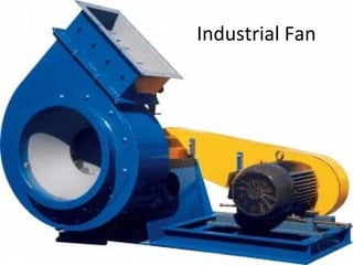
Industrial fan(ID FD Fans)
•Télécharger en tant que PPT, PDF•
35 j'aime•29,683 vues

ID FD FAN

Recommandé
Contenu connexe
Tendances
Tendances (20)
Similaire à Industrial fan(ID FD Fans)
Similaire à Industrial fan(ID FD Fans) (20)
Dernier
Dernier (20)
Industrial fan(ID FD Fans)
- 2. Draft System The function of draft in a combustion system is to exhaust the products of combustion into the atmosphere. The draft can be classified into two types namely Natural and Mechanical Draft. Natural Draft It is the draft produced by a chimney alone. It is caused by the difference in weight between the column of hot gas inside the chimney and column of outside air of the same height and cross section. Being much lighter than outside air, chimney flue gas tends to rise, and the heavier outside air flows in through the ash pit to take its place. It is usually controlled by hand-operated dampers in the chimney and breeching connecting the boiler to the chimney. Here no fans or blowers are used. The products of combustion are discharged at such a height that it will not be a nuisance to the surrounding community.
- 3. Mechanical Draft It is draft artificially produced by fans. Three basic types of drafts that are applied are : Balanced Draft: Forced-draft (F-D) fan (blower) pushes air into the furnace and an induced draft (I-D) fan draws gases into the chimney thereby providing draft to remove the gases from the boiler. Here the pressure is maintained between 0.05 to 0.10 in. of water gauge below atmospheric pressure in the case of boilers and slightly positive for reheating and heat treatment furnaces. Induced Draft: An induced-draft fan draws enough draft for flow into the furnace, causing the products of combustion to discharge to atmosphere. Here the furnace is kept at a slight negative pressure below the atmospheric pressure so that combustion air flows through the system. Forced Draft: The Forced draft system uses a fan to deliver the air to the furnace, forcing combustion products to flow through the unit and up the stack.
- 4. ID FD Fan – Scheme of Boiler
- 5. Induced Draft Advantages •Better distribution of air across the bundle. •Less possibility of hot effluent air recirculating into the intake. The hot air is discharged upward at approximately 2.5 times the intake velocity, or about 1,500 feet per minute. •Better process control and stability because the plenum covers 60% of the bundle face area, reducing the effects of sun, rain, and hall. •Increased capacity in the fan-off or fan failure condition, since the natural draft stack effect is much greater. Disadvantages and limitations •Possibly higher horsepower requirements if the effluent air is very hot. •Effluent air temperature should be limited to 220°F to prevent damage to fan blades, bearings, or other mechanical equipment in the hot air stream. When the process inlet temperature exceeds 350°F, forced draft design should be considered because high effluent air temperatures may occur during fan-off or low air flow operation. •Fans are less accessible for maintenance, and maintenance may have to be done in the hot air generated by natural convection. •Plenums must be removed to replace bundles.
- 6. Induced Draft & Forced Draft
- 7. Forced Draft Advantages •Possibly lower horsepower requirements if the effluent air is very hot. (Horsepower varies inversely with the absolute temperature.) •Better accessibility of fans and upper bearings for maintenance. •Better accessibility of bundles for replacement. •Accommodates higher process inlet temperatures. Disadvantages •Less uniform distribution of air over the bundle. •Increased possibility of hot air recirculation, resulting from low discharge velocity from the bundles, high intake velocity to the fan ring, and no stack. •Low natural draft capability on fan failure. •Complete exposure of the finned tubes to sun, rain, and hail, which results in poor process control and stability. In most cases the advantages of induced draft design outweigh the disadvantages.
- 8. Fan is a machine used to add energy to the gaseous fluid to increase its pressure. Fans are used where low pressures (from a few mm of water to (50 mm Hg) and comparatively large volume are required. They run at relatively low speed, the casing and impeller usually built of sheet iron. FAN TYPES 1) AXIAL FLOW FANS - the flow of the gases is parallel to the fan shaft. a. tube axial b. vane axial c. Propeller 2) RADIAL OR CENTRIFUGAL FLOW FANS- the flow of gases depends upon the centrifugal action of the impeller or rotor. a. Straight blades b. Forward curved blades c. Backward curved blades d. Double curved blades
- 9. Propeller Fan Tubeaxial Fan Vaneaxial Fan Air in Air out Motor Rotor Housing Centrifugal Fan
- 11. 1. Inlet Support 2. Inlet Sleeve 3. Inlet Cone/Cylinder 4. Wheel (BISW shown) 5. Shaft 6. Housing 7. Housing/Bearing Pedestal Assembly 8. Drive Side Support 9. Bearings Construction
- 13. Construction
- 14. Construction
- 21. COMMON USES OF FANS 1. Ventilation and air conditioning 2. Forced and induced draft service for boilers 3. Dust collection 4. Drying and cooling of materials 5. Cooling towers 6. Mine and tunnel ventilation 7. Pneumatic conveying and other industrial process work Head Calculations 1 2 suction discharge For a fan ∆Z = 0 ; ∆PE = 0 and Q = 0, because fans are designed to overcome fluid friction. No cooling system is needed due to small temperature differential between suction and discharge.
- 22. Boiler ID fan selection There are many factors that need to be taken into account when looking at the fan requirements Noise–what is the allowable noise limit? Application–does the gas stream contain solids or particulates? Is the gas stream explosive? Is the fan in a hazardous zone? Corrosion–is the gas stream corrosive? If so, a selection of materials and/or coatings should be designed to resist corrosion. Control–what type of control does the fan require? Devices such as variable inlet vanes, dampers and variable frequency drives should be considered. Gas density–this needs to take into account the altitude, temperature, humidity, and negative barometric pressure and gas combinations. Duty location–what part of the fan curve is the system to operate in?
- 23. Entry/exit conditions–will the entry/exit conditions allow the fan to operate at its design point? If excessive turbulence is present, then the impeller may not properly impart energy on the airstream. Accessories–consider application and cost or accessories such as vibration or temperature monitoring, flow control or acoustic treatment. Foundations–where is the fan to be located? If above ground on a structure, then consider what level of isolation is required. Maintenance–consider fan location; provide safe and adequate working space and access for lifting equipment.
- 24. INSTALLATION Position the fan in such a way to assure minimum space for the maintenance and repair work. Foundations The foundation should, by preference, be made in reinforced concrete and its minimum weight must to be four times the weight of the rotating mass (around double the total static weight).
- 25. POSITIONING Take the anti-vibrations supports (if included with the supply) from the plastic bag attached to the fan. Lift up the fan, remove the wood feets and install the anti vibrations supports.
- 26. Coupling Installation Remove all foreign material from the fan and motor shafts and coat with machine oil for easy mounting of the coupling halves Mount the coupling halves on each shaft, setting the gap between the faces as specified Lightly polish the shafts with crocus cloth if necessary in order to avoid using excessive force. Align the coupling to within the manufacturer's limits for parallel and angular misalignment
- 27. Flexible Coupling Installation and Alignment These instructions cover, in general, the installation of flexible couplings of the pin, gear, or grid types. 1. Before mounting coupling(s), be sure all bearing(s), inlet vane(s), etc., have been installed. 2. Install each coupling half cover with an "O" ring on its shaft. 3. Determine which direction, long or short shank of coupling hub should be located; see manufacturer's manual. 4. Heat coupling hub to approximately 300OF by means of hot oil bath or oven. Do not apply flame to hub teeth. 5. Install coupling hub(s) on shaft. Hub and shaft face should be flush. 6. Key the couplings to the shafts while the hub(s) are still hot. 7. Adjust the clearance between the coupling faces. 8. When a sleeve bearing motor is used, locate it so that when the motor rotor is closest to the fan, the motor shaft will not touch the fan shaft. It the motor shaft has its magnetic center marked, align it in this position; otherwise equally divide the maximum play to obtain the mechanical center 9. With tapered wedge, feeler gauges, or dial indicator, observe that the faces of the fan and driver couplings are parallel. 10. Align the shafts until a straightedge appears to be parallel to the shafts. Repeat at three additional points at 900 from each other. Recheck angular alignment and hub separation.
- 28. Damper Installation When installing dampers in the field, refer to the assembly drawing to assure that damper linkage is in the proper position and the blades rotate from closed to open position in the correct rotation. Desired fan performance may not be obtained if proper damper blade rotation shown on drawing is not observed. Double width fans using two dampers operate with a single control arm and a shaft connecting the two dampers. Blades in both dampers must fully open and close together. The connecting shaft often is in two pieces and although a setscrew is provided in the coupling as an aid for assembly, this section should be field welded to the shaft after the damper blades are synchronized. Fans operating at higher temperatures have shaft-coupling arrangement to provide for expansion; do not weld both ends to the shaft.
- 30. Bearing Standard grease lubricated fan bearings should be maintained with high quality lithium based grease conforming to NLGI grade 2 consistency. Avoid mixing greases with different bases, as they may be incompatible and result in rapid deterioration of the lubricant and premature bearing failure. Prepare Bearings, Set Rotor Assembly: 1. For Sleeve Bearings: Remove bearing caps and clean bearings with solvent; Coat with clean oil and cover to avoid contamination. Clean oil rings and shaft seals. Do not mix parts between the bearings, as they are not interchangeable. Bolt the lower half of the bearing loosely in place. Again cover to prevent contamination. Sling the rotor assembly as previously described. To prevent damage to the liner in the fixed bearing (having the thrust collars) when puffing large rotor assemblies in place follow this procedure: The rotor assembly is to be positioned above the bearing journals and the liner for the fixed bearing is then fastened to the shaft and lowered into the bearing housing with the rotor assembly.
- 31. 2. For Anti-friction Bearings-Solid Pillow Blocks: Non-split pillow blocks are slipped over the shaft ends prior to putting the rotor in place, Check to insure that the floating bearing (unless specified on the assembly drawing) is on the side opposite the driver. See figure . Bolt bearings loosely on pedestals. 3.For Anti-friction (roller) Bearings-Adapter mount, Split Pillow Block: ~ Cleaning of internal parts should not be required as the corrosion preventative compound applied by the manufacturer is compatible with recommended lubricants. Careful inspection of all internal parts is good practice, as any corrosion present is likely to cause problems at a later date. Do not mix parts between bearings as they may not be Interchangeable
- 32. STARTING Before starting up it is important to carry out various checks : check that the bearings of the fan and motor are correctly lubricated. Make sure the drive flexible connection is adequately lubricated. Make sure that all the bolts are fully tightened, with a torque force indicated in the table below In particularly be careful with the bolts of support
- 33. Check ,that there is no foreign matter inside the fan
- 34. Check the alignment of the pulleysCheck the alignment of the coupling joint Rotate the impeller by hand to be sure that it does not touch the walls
- 35. Check the tension of the belts Check that the access door is closed
- 39. Vibration check
- 41. TROUBLESHOOTING