SlideShare une entreprise Scribd logo
1  sur  10
Télécharger pour lire hors ligne
2. TELECOMMUNICATIONS BASICS
The purpose of any telecommunications system is to transfer information
from the sender to the receiver by a means of a communication channel.
The information is carried by a signal, which is certain physical quantity
that changes with time.
The signal can be a voltage proportional to the amplitude of the voice,
like in a simple telephone, a sequence of pulses of light in an optical fibre,
or a radio-electric wave irradiated by an antenna.
For analog signals, these variations are directly proportional to some
physical variable like sound, light, temperature, wind speed, etc. The
information can also be transmitted by digital binary signals, that will have
only two values, a digital one and a digital zero. Any analog signal can be
converted into a digital signal by appropriately sampling and then coding
it. The sampling frequency must be at least twice the maximum frequency
present in the signal in order to carry all the information contained
therein. Random signals are the ones that are unpredictable and can be
described only by statistical means.
Noise is a typical random signal, described by its mean power and
frequency distribution. A signal can be characterised by its behaviour over
time or by its frequency components, which constitute its spectrum. Some
examples of signals are shown in Figure TB 1.
Figure TB 1: Examples of signals
Any periodic signal is composed of many sinusoidal components, all of them
multiples of the fundamental frequency, which is the inverse of the period of
the signal. So a signal can be characterised either by a graph of its amplitude
over time, called a waveform, or a graph of of the amplitudes of its frequency
components, called a spectrum.
Figure TB 2: Waveforms, Spectrum and filters
Figure TB 2 shows how the same signal can be seen from two different
perspectives. The waveform can be displayed by an instrument called an
oscilloscope, while the spectrum can be displayed by what is called a
Spectrum Analyzer. The spectrum distribution relays very important
information about the signal and allows for the intuitive understanding of
the concept of filtering of electrical signals. In the example shown, the
signal is formed by the superposition of three sinusoidal components of
frequency f1, f2 and f3. If we pass this signal through a device that will
remove f2 and f3, the output is a pure sinusoidal at frequency f1.
We call this operation “Low Pass filtering” because it removes the
higher frequencies. Conversely, we can apply the signal to a “High
Pass Filter”, a device that will remove f1 and f2 leaving only a
sinusoidal signal at the f3 frequency. Other combinations are
possible, giving rise to a variety of filters. No physical device can
transmit all the infinite frequencies of the radio-electric spectrum,
so every device will always perform some extent of filtering to the
signal that goes through it. The bandwidth of a signal is the
difference between the highest and the lowest frequency that it
contains and is expressed in Hz (number of cycles per second).
While travelling through the communication channel, the signal is subject
to interference caused by other signals and is also affected by the electrical
noise always present in any electrical or optical component. Intra-channel
interference originates in the same channel as our signal. Co-channel
interference is due to the imperfection of the filters that will let in signals
from adjacent channels.
Consequently, the received signal will always be a distorted replica of the
transmitted signal, from which the original information must be retrieved
by appropriate means to combat the effect of interference and noise.
Furthermore, the received signal will be subject to attenuation and delay
that increase with the distance between the transmitter and the receiver.
Figure TB 3: Attenuation and delay
Although it is relatively simple to restore the amplitude of signal by means
of an electrical amplifier, the components of the amplifier will add
additional noise to the signal, so at very long distances where the received
signal is feeble, the amplifier will produce a signal so garbled with noise
that the information originally transmitted will no longer be retrievable.
One way to address this problem consists in converting the continuous
quantity carrying the information into a sequence of very simple symbols
which can be easier to recognise even at great distance. For instance, the
flag of a ship is a convenient way to distinguish the nationality of the ship
even at distances at which the letters on the hull cannot be read.
This technique has been extended to carry generalised messages by
assigning different position of flags to every letter of the alphabet, in an
early form of long distance telecommunications by means of digital or
numeric signals.
The limitation of this method is obvious; to be able to distinguish among,
say, 26 symbols corresponding to each letters of the alphabet, one must be
quite close to the communicating ship.
On the other hand, if we code each letter of the alphabet in a sequence of
only two symbols, these symbols can be distinguished at much longer
distance, for example the dot and dashes of the telegraph system.
The process of transforming a continuous analog signal into a
discontinuous digital one is called Analog to Digital Conversion (ADC),
and conversely we must have a Digital to Analog Converter (DAC) at the
receiving end to retrieve the original information.
This is the reason why most modern telecommunication systems use
digital binary signals to convey all sorts of information in a more robust
way. The receiver must only distinguish between two possible symbols, or
in other words between two possible values of the received bit (binary
digit). For instance, the CD has replaced the vinyl record, and analogue
television is being replaced by digital television. Digital signals can use less
bandwidth, as exemplified by the “digital dividend” currently being
harnessed in many countries which consists in bandwidth that has become
available thanks to the transition from analog to digital transmission in
TV broadcasting.
Although in the process of converting from an analog to a digital
information system there is always some loss of information, we can
engineer the system so as to make this loss negligible.
Figure TB 4: Undersampled Image
For example, in a digital camera we can choose the number of bits used to
record the image.
The greater the number of bits (proportional to the amount of megapixels),
the better the rendering, but more memory will be used and longer time to
transmit the image will be needed.
So most modern communication systems deal with digital signals, although
the original variable that we want to transmit might be analog, like the voice.
It can be shown that any analog signal can be reconstructed from discrete
samples if the sampling rate is at least twice as high as the highest frequency
content of the signal.
Figure TB 5: detection of a noisy signal
Then each sample is coded in as many bits as necessary to achieve the desired
amount of precision.
These bits can now be efficiently stored or transmitted, since for the recovery
of the information one needs to distinguish among only two states, and not
among the infinite nuances of an analog signal.
This is shown in Figure TB 5, where the original data consists of the 0 1 0
1 1 1 0 sequence. The 0's are represented as zero volts and the 1's as 1 V.
As the signal moves towards the receiver, its amplitude will diminish. This
effect is called "attenuation" and is shown in the figure. Likewise, there
will also be a delay as the signal moves from the transmitter to the
receiver, the variability in the delay of the received signal is called jitter.
Attenuation, noise or jitter (or their combination) if severe enough, can
cause a detection error. An amplifier can be used to overcome the
attenuation, but the electrical noise always present in the system will add
to the received signal.
The noisy received signal is therefore quite different from the original
signal, but in a digital system we can still recover the information
contained by sampling the received signal at the correct time and
comparing the value at the sampling time with a suitable threshold
voltage. In this example the noise received signal has a peak of 1.8 V, so
we might choose e threshold voltage of 1.1 V. If the received signal is
above the threshold, the detector will output a digital 1, otherwise, it will
output a 0. In this case we can see that because of the effect of the noise
the fifth bit was erroneously detected as a zero.
Transmission errors can also occur if the sampling signal period is different
from that of the original data (difference in the clock rates), or if the
receiver clock is not stable enough (jitter).
Any physical system will have an upper limit in the frequencies that will
transmit faithfully (the bandwidth of the system), higher frequencies will
be blocked, so the abrupt rise and fall of the voltage will be smoothed out
as the signal goes through the channel.
Therefore, we must make sure that each of the elements of the system has
enough bandwidth to handle the signal. On the other hand, the greater
the bandwidth of the receiver system, the greater the amount of the noise
that will affect the received signal.
Modulation
The robustness of the digital signal is also exemplified by the fact that it
was chosen for the first trials of radio transmission. Marconi showed the
feasibility of long distance transmission, but pretty soon realised that there
was a need to share the medium among different users.
This was achieved by assigning different carrier frequencies which were
modulated by each user’s message. Modulation is a scheme to modify the
amplitude, frequency or phase of the carrier according with the information
one wants to transmit. The original information is retrieved at destination
by the corresponding demodulation of the received signal.
Figure TB 6: Sinusoidal Carrier Signal
Figure TB 6 shows a carrier signal with Amplitude A, phase θ, and
frequency fo which is the reciprocal of the period T.
The combination of different modulation schemes has resulted in a
plethora of modulation techniques depending on which aspect one wants
to optimise: robustness against noise, amount of information transmitted
per second (capacity of the link in bits/second) or spectral efficiency
(number of bits/s per Hertz).
For instance, BPSK -Binary Phase Shift Keying- is a very robust
modulation technique but transmits only one bit per symbol, while 256
QAM -Quaternary Amplitude Modulation- will carry 8 bits per symbol,
thus multiplying by a factor of eight the amount of information
transmitted per second, but to correctly distinguish amongst the 256
symbols transmitted, the received signal must be very strong as compared
with the noise (a very high S/N -Signal/Noise ratio- is required).
The ultimate measure of quality in digital transmission is the BER -Bit
Error Rate- which corresponds to the fraction of erroneously decoded bits.
Typical values of BER range between 10-3
and 10-9
.
The modulation also allows us to choose which range of frequency we
want to use for a given transmission. All frequencies are not created equal
and the choice of the carrier frequency is determined by legal, commercial
and technical constraints.
Multiplexing and duplexing
In general, the sharing of a channel among different users is called
multiplexing.
This is shown in Figure TB 7.
Assigning different carrier frequencies to different users is called FDMA
-Frequency Division Multiple Access-.
An alternative technique consists in assigning different time slots to
different users, in what is known as TDMA -Time Division Multiple
Access-, or even different codes in CDMA -Code Division Multiple
Access- where the different users are recognised at the receiver by the
particular mathematical code assigned to them. See Figure TB 8.
By using two or more antennas simultaneously, one can take advantage of
the different amount of fading introduced in the different paths to the
receiver establishing a difference among users in what is known as SDMA
- Space Division Multiple Access-, a technique employed in the MIMO
-Multiple Input,Multiple Output- systems that have gained popularity
recently.
Figure TB 8: Medium Sharing techniques
Most communication systems transmit information in both directions, for
instance from the Base Station to the subscriber in what is called the
downlink, and from the subscriber to the base station in the uplink.
To accomplish this, the channel must be shared between the two
directions giving rise respectively to FDD -Frequency Division Duplexing-
and TDD -Time Division Duplexing-.
Conclusions
The communication system must overcome the noise and interference to
deliver a suitable replica of the signal to the receiver.
The capacity of the communication channel in bits/second is proportional
to the bandwidth in Hz and to the logarithm of the S/N ratio.
Modulation is used to adapt the signal to the channel and to allow several
signals to share the same channel. Higher order modulation schemes allow
for a higher transmission rate, but require higher S/N ratio.
The channel can be shared by several users that occupy different
frequencies, different time slots, different codes or by taking advantage of
different propagation characteristics in what is called spatial multiplexing.
For more information and slides covering this topic please visit
http://wtkit.org/groups/wtkit/wiki/820cb/download_page.html

Contenu connexe

Tendances

Communication systems v3
Communication systems v3Communication systems v3
Communication systems v3babak danyal
 
03 data transmission
03 data transmission03 data transmission
03 data transmissionOrbay Yeşil
 
Communications
CommunicationsCommunications
CommunicationsWaqas !!!!
 
Transmission of digital signals
Transmission of digital signalsTransmission of digital signals
Transmission of digital signalsSachin Artani
 
311 introduction to communication system
311 introduction to communication system311 introduction to communication system
311 introduction to communication systemMohammad Bappy
 
Analog communication System Basic Introduction by A Sravan Kumar
Analog communication System Basic Introduction  by A Sravan KumarAnalog communication System Basic Introduction  by A Sravan Kumar
Analog communication System Basic Introduction by A Sravan KumarAPPALASRAVANKUMAR
 
Basics of signals data communication
Basics of signals data communicationBasics of signals data communication
Basics of signals data communicationSyed Bilal Zaidi
 
Data Communication Principles
Data Communication PrinciplesData Communication Principles
Data Communication PrinciplesKamal Acharya
 
1- Principles of Wireless Trans..pdf
1- Principles of Wireless Trans..pdf1- Principles of Wireless Trans..pdf
1- Principles of Wireless Trans..pdfed8dc9f63e
 
Digital Transmission Fundamentals
Digital Transmission FundamentalsDigital Transmission Fundamentals
Digital Transmission FundamentalsAisu
 
Satellite communication analog and digital signals
Satellite communication analog and digital signalsSatellite communication analog and digital signals
Satellite communication analog and digital signalsAjay Kumar
 
Communication system lec 8
Communication system lec 8Communication system lec 8
Communication system lec 8ZareenRauf1
 
Digital & analog transmission
Digital & analog transmissionDigital & analog transmission
Digital & analog transmissionJeffery Vava
 
Digital communication systems
Digital communication systemsDigital communication systems
Digital communication systemsNisreen Bashar
 
Noise in Communication System
Noise in Communication SystemNoise in Communication System
Noise in Communication SystemIzah Asmadi
 
Communication systems v4
Communication systems v4Communication systems v4
Communication systems v4babak danyal
 
communication system Chapter 6
communication system Chapter 6communication system Chapter 6
communication system Chapter 6moeen khan afridi
 
311 communication system concepts
311 communication system concepts311 communication system concepts
311 communication system conceptsMohammad Bappy
 

Tendances (20)

Communication systems v3
Communication systems v3Communication systems v3
Communication systems v3
 
03 data transmission
03 data transmission03 data transmission
03 data transmission
 
Communications
CommunicationsCommunications
Communications
 
Transmission of digital signals
Transmission of digital signalsTransmission of digital signals
Transmission of digital signals
 
311 introduction to communication system
311 introduction to communication system311 introduction to communication system
311 introduction to communication system
 
Analog communication System Basic Introduction by A Sravan Kumar
Analog communication System Basic Introduction  by A Sravan KumarAnalog communication System Basic Introduction  by A Sravan Kumar
Analog communication System Basic Introduction by A Sravan Kumar
 
Basics of signals data communication
Basics of signals data communicationBasics of signals data communication
Basics of signals data communication
 
Data Communication Principles
Data Communication PrinciplesData Communication Principles
Data Communication Principles
 
1- Principles of Wireless Trans..pdf
1- Principles of Wireless Trans..pdf1- Principles of Wireless Trans..pdf
1- Principles of Wireless Trans..pdf
 
Digital Transmission Fundamentals
Digital Transmission FundamentalsDigital Transmission Fundamentals
Digital Transmission Fundamentals
 
2. data and signals
2. data and signals2. data and signals
2. data and signals
 
Ripple Control Receiver
Ripple Control ReceiverRipple Control Receiver
Ripple Control Receiver
 
Satellite communication analog and digital signals
Satellite communication analog and digital signalsSatellite communication analog and digital signals
Satellite communication analog and digital signals
 
Communication system lec 8
Communication system lec 8Communication system lec 8
Communication system lec 8
 
Digital & analog transmission
Digital & analog transmissionDigital & analog transmission
Digital & analog transmission
 
Digital communication systems
Digital communication systemsDigital communication systems
Digital communication systems
 
Noise in Communication System
Noise in Communication SystemNoise in Communication System
Noise in Communication System
 
Communication systems v4
Communication systems v4Communication systems v4
Communication systems v4
 
communication system Chapter 6
communication system Chapter 6communication system Chapter 6
communication system Chapter 6
 
311 communication system concepts
311 communication system concepts311 communication system concepts
311 communication system concepts
 

En vedette

правила інтернет безпеки для підлітків
правила інтернет безпеки для підлітківправила інтернет безпеки для підлітків
правила інтернет безпеки для підлітківJoey Badass
 
Lançamentos março das Editoras Arqueiro e Sextante
Lançamentos março das Editoras Arqueiro e SextanteLançamentos março das Editoras Arqueiro e Sextante
Lançamentos março das Editoras Arqueiro e SextanteClaudia Valeria Ortega
 
Acta Reunió AMPA 6 de febrer
Acta Reunió AMPA 6 de febrerActa Reunió AMPA 6 de febrer
Acta Reunió AMPA 6 de febreroriolllop
 
3.Properties of signals
3.Properties of signals3.Properties of signals
3.Properties of signalsINDIAN NAVY
 
المحاضرة الثالثة - منظومة المنهج
المحاضرة الثالثة - منظومة المنهجالمحاضرة الثالثة - منظومة المنهج
المحاضرة الثالثة - منظومة المنهجIntesar Almugren
 
parametric method of power spectrum Estimation
parametric method of power spectrum Estimationparametric method of power spectrum Estimation
parametric method of power spectrum Estimationjunjer
 
Mayor menor cocodrilo quique
Mayor menor cocodrilo quiqueMayor menor cocodrilo quique
Mayor menor cocodrilo quiquenoeliach
 
Lecture2 Signal and Systems
Lecture2 Signal and SystemsLecture2 Signal and Systems
Lecture2 Signal and Systemsbabak danyal
 
Noice canclellation using adaptive filters with adpative algorithms(LMS,NLMS,...
Noice canclellation using adaptive filters with adpative algorithms(LMS,NLMS,...Noice canclellation using adaptive filters with adpative algorithms(LMS,NLMS,...
Noice canclellation using adaptive filters with adpative algorithms(LMS,NLMS,...Brati Sundar Nanda
 

En vedette (12)

правила інтернет безпеки для підлітків
правила інтернет безпеки для підлітківправила інтернет безпеки для підлітків
правила інтернет безпеки для підлітків
 
Lançamentos março das Editoras Arqueiro e Sextante
Lançamentos março das Editoras Arqueiro e SextanteLançamentos março das Editoras Arqueiro e Sextante
Lançamentos março das Editoras Arqueiro e Sextante
 
Acta Reunió AMPA 6 de febrer
Acta Reunió AMPA 6 de febrerActa Reunió AMPA 6 de febrer
Acta Reunió AMPA 6 de febrer
 
Focus2006
Focus2006Focus2006
Focus2006
 
Act3.bloque1
Act3.bloque1Act3.bloque1
Act3.bloque1
 
3.Properties of signals
3.Properties of signals3.Properties of signals
3.Properties of signals
 
المحاضرة الثالثة - منظومة المنهج
المحاضرة الثالثة - منظومة المنهجالمحاضرة الثالثة - منظومة المنهج
المحاضرة الثالثة - منظومة المنهج
 
parametric method of power spectrum Estimation
parametric method of power spectrum Estimationparametric method of power spectrum Estimation
parametric method of power spectrum Estimation
 
Final ppt
Final pptFinal ppt
Final ppt
 
Mayor menor cocodrilo quique
Mayor menor cocodrilo quiqueMayor menor cocodrilo quique
Mayor menor cocodrilo quique
 
Lecture2 Signal and Systems
Lecture2 Signal and SystemsLecture2 Signal and Systems
Lecture2 Signal and Systems
 
Noice canclellation using adaptive filters with adpative algorithms(LMS,NLMS,...
Noice canclellation using adaptive filters with adpative algorithms(LMS,NLMS,...Noice canclellation using adaptive filters with adpative algorithms(LMS,NLMS,...
Noice canclellation using adaptive filters with adpative algorithms(LMS,NLMS,...
 

Similaire à Telecom Basics: Digital Signals

Similaire à Telecom Basics: Digital Signals (20)

Communications
CommunicationsCommunications
Communications
 
Unit 5.doc
Unit 5.docUnit 5.doc
Unit 5.doc
 
Unit 5.doc
Unit 5.docUnit 5.doc
Unit 5.doc
 
COMPUTER NETWORKS DATAS AND SIGNALS.pptx
COMPUTER NETWORKS DATAS AND SIGNALS.pptxCOMPUTER NETWORKS DATAS AND SIGNALS.pptx
COMPUTER NETWORKS DATAS AND SIGNALS.pptx
 
LECTURE 3.pptx
LECTURE 3.pptxLECTURE 3.pptx
LECTURE 3.pptx
 
Module ii physical layer
Module ii physical layerModule ii physical layer
Module ii physical layer
 
Wireless communication
Wireless communicationWireless communication
Wireless communication
 
Comms 1.docx
Comms 1.docxComms 1.docx
Comms 1.docx
 
Source coding systems
Source coding systemsSource coding systems
Source coding systems
 
dc1.pdf
dc1.pdfdc1.pdf
dc1.pdf
 
Radio Conformance Test
Radio Conformance TestRadio Conformance Test
Radio Conformance Test
 
Communication systems
Communication systemsCommunication systems
Communication systems
 
03 data transmission
03 data transmission03 data transmission
03 data transmission
 
M2 l1
M2 l1M2 l1
M2 l1
 
W02 l03 information-communication (1)
W02 l03 information-communication (1)W02 l03 information-communication (1)
W02 l03 information-communication (1)
 
Data Communication and Computer Networks
Data Communication and Computer NetworksData Communication and Computer Networks
Data Communication and Computer Networks
 
Assignment 4
Assignment 4 Assignment 4
Assignment 4
 
Rf fundamentals
Rf fundamentalsRf fundamentals
Rf fundamentals
 
Unit-1_Analog Communication_PPT (1).pptx
Unit-1_Analog Communication_PPT (1).pptxUnit-1_Analog Communication_PPT (1).pptx
Unit-1_Analog Communication_PPT (1).pptx
 
Lecture 1 introduction and signals analysis
Lecture 1 introduction and signals analysisLecture 1 introduction and signals analysis
Lecture 1 introduction and signals analysis
 

Dernier

Unraveling Multimodality with Large Language Models.pdf
Unraveling Multimodality with Large Language Models.pdfUnraveling Multimodality with Large Language Models.pdf
Unraveling Multimodality with Large Language Models.pdfAlex Barbosa Coqueiro
 
Transcript: New from BookNet Canada for 2024: BNC CataList - Tech Forum 2024
Transcript: New from BookNet Canada for 2024: BNC CataList - Tech Forum 2024Transcript: New from BookNet Canada for 2024: BNC CataList - Tech Forum 2024
Transcript: New from BookNet Canada for 2024: BNC CataList - Tech Forum 2024BookNet Canada
 
"LLMs for Python Engineers: Advanced Data Analysis and Semantic Kernel",Oleks...
"LLMs for Python Engineers: Advanced Data Analysis and Semantic Kernel",Oleks..."LLMs for Python Engineers: Advanced Data Analysis and Semantic Kernel",Oleks...
"LLMs for Python Engineers: Advanced Data Analysis and Semantic Kernel",Oleks...Fwdays
 
The Future of Software Development - Devin AI Innovative Approach.pdf
The Future of Software Development - Devin AI Innovative Approach.pdfThe Future of Software Development - Devin AI Innovative Approach.pdf
The Future of Software Development - Devin AI Innovative Approach.pdfSeasiaInfotech2
 
"Subclassing and Composition – A Pythonic Tour of Trade-Offs", Hynek Schlawack
"Subclassing and Composition – A Pythonic Tour of Trade-Offs", Hynek Schlawack"Subclassing and Composition – A Pythonic Tour of Trade-Offs", Hynek Schlawack
"Subclassing and Composition – A Pythonic Tour of Trade-Offs", Hynek SchlawackFwdays
 
DevEX - reference for building teams, processes, and platforms
DevEX - reference for building teams, processes, and platformsDevEX - reference for building teams, processes, and platforms
DevEX - reference for building teams, processes, and platformsSergiu Bodiu
 
DevoxxFR 2024 Reproducible Builds with Apache Maven
DevoxxFR 2024 Reproducible Builds with Apache MavenDevoxxFR 2024 Reproducible Builds with Apache Maven
DevoxxFR 2024 Reproducible Builds with Apache MavenHervé Boutemy
 
Connect Wave/ connectwave Pitch Deck Presentation
Connect Wave/ connectwave Pitch Deck PresentationConnect Wave/ connectwave Pitch Deck Presentation
Connect Wave/ connectwave Pitch Deck PresentationSlibray Presentation
 
Advanced Test Driven-Development @ php[tek] 2024
Advanced Test Driven-Development @ php[tek] 2024Advanced Test Driven-Development @ php[tek] 2024
Advanced Test Driven-Development @ php[tek] 2024Scott Keck-Warren
 
Streamlining Python Development: A Guide to a Modern Project Setup
Streamlining Python Development: A Guide to a Modern Project SetupStreamlining Python Development: A Guide to a Modern Project Setup
Streamlining Python Development: A Guide to a Modern Project SetupFlorian Wilhelm
 
Kotlin Multiplatform & Compose Multiplatform - Starter kit for pragmatics
Kotlin Multiplatform & Compose Multiplatform - Starter kit for pragmaticsKotlin Multiplatform & Compose Multiplatform - Starter kit for pragmatics
Kotlin Multiplatform & Compose Multiplatform - Starter kit for pragmaticscarlostorres15106
 
Story boards and shot lists for my a level piece
Story boards and shot lists for my a level pieceStory boards and shot lists for my a level piece
Story boards and shot lists for my a level piececharlottematthew16
 
New from BookNet Canada for 2024: BNC CataList - Tech Forum 2024
New from BookNet Canada for 2024: BNC CataList - Tech Forum 2024New from BookNet Canada for 2024: BNC CataList - Tech Forum 2024
New from BookNet Canada for 2024: BNC CataList - Tech Forum 2024BookNet Canada
 
Nell’iperspazio con Rocket: il Framework Web di Rust!
Nell’iperspazio con Rocket: il Framework Web di Rust!Nell’iperspazio con Rocket: il Framework Web di Rust!
Nell’iperspazio con Rocket: il Framework Web di Rust!Commit University
 
Designing IA for AI - Information Architecture Conference 2024
Designing IA for AI - Information Architecture Conference 2024Designing IA for AI - Information Architecture Conference 2024
Designing IA for AI - Information Architecture Conference 2024Enterprise Knowledge
 
Gen AI in Business - Global Trends Report 2024.pdf
Gen AI in Business - Global Trends Report 2024.pdfGen AI in Business - Global Trends Report 2024.pdf
Gen AI in Business - Global Trends Report 2024.pdfAddepto
 
Artificial intelligence in cctv survelliance.pptx
Artificial intelligence in cctv survelliance.pptxArtificial intelligence in cctv survelliance.pptx
Artificial intelligence in cctv survelliance.pptxhariprasad279825
 
AI as an Interface for Commercial Buildings
AI as an Interface for Commercial BuildingsAI as an Interface for Commercial Buildings
AI as an Interface for Commercial BuildingsMemoori
 

Dernier (20)

Unraveling Multimodality with Large Language Models.pdf
Unraveling Multimodality with Large Language Models.pdfUnraveling Multimodality with Large Language Models.pdf
Unraveling Multimodality with Large Language Models.pdf
 
Transcript: New from BookNet Canada for 2024: BNC CataList - Tech Forum 2024
Transcript: New from BookNet Canada for 2024: BNC CataList - Tech Forum 2024Transcript: New from BookNet Canada for 2024: BNC CataList - Tech Forum 2024
Transcript: New from BookNet Canada for 2024: BNC CataList - Tech Forum 2024
 
"LLMs for Python Engineers: Advanced Data Analysis and Semantic Kernel",Oleks...
"LLMs for Python Engineers: Advanced Data Analysis and Semantic Kernel",Oleks..."LLMs for Python Engineers: Advanced Data Analysis and Semantic Kernel",Oleks...
"LLMs for Python Engineers: Advanced Data Analysis and Semantic Kernel",Oleks...
 
The Future of Software Development - Devin AI Innovative Approach.pdf
The Future of Software Development - Devin AI Innovative Approach.pdfThe Future of Software Development - Devin AI Innovative Approach.pdf
The Future of Software Development - Devin AI Innovative Approach.pdf
 
"Subclassing and Composition – A Pythonic Tour of Trade-Offs", Hynek Schlawack
"Subclassing and Composition – A Pythonic Tour of Trade-Offs", Hynek Schlawack"Subclassing and Composition – A Pythonic Tour of Trade-Offs", Hynek Schlawack
"Subclassing and Composition – A Pythonic Tour of Trade-Offs", Hynek Schlawack
 
DevEX - reference for building teams, processes, and platforms
DevEX - reference for building teams, processes, and platformsDevEX - reference for building teams, processes, and platforms
DevEX - reference for building teams, processes, and platforms
 
DevoxxFR 2024 Reproducible Builds with Apache Maven
DevoxxFR 2024 Reproducible Builds with Apache MavenDevoxxFR 2024 Reproducible Builds with Apache Maven
DevoxxFR 2024 Reproducible Builds with Apache Maven
 
Connect Wave/ connectwave Pitch Deck Presentation
Connect Wave/ connectwave Pitch Deck PresentationConnect Wave/ connectwave Pitch Deck Presentation
Connect Wave/ connectwave Pitch Deck Presentation
 
Advanced Test Driven-Development @ php[tek] 2024
Advanced Test Driven-Development @ php[tek] 2024Advanced Test Driven-Development @ php[tek] 2024
Advanced Test Driven-Development @ php[tek] 2024
 
Streamlining Python Development: A Guide to a Modern Project Setup
Streamlining Python Development: A Guide to a Modern Project SetupStreamlining Python Development: A Guide to a Modern Project Setup
Streamlining Python Development: A Guide to a Modern Project Setup
 
Kotlin Multiplatform & Compose Multiplatform - Starter kit for pragmatics
Kotlin Multiplatform & Compose Multiplatform - Starter kit for pragmaticsKotlin Multiplatform & Compose Multiplatform - Starter kit for pragmatics
Kotlin Multiplatform & Compose Multiplatform - Starter kit for pragmatics
 
Story boards and shot lists for my a level piece
Story boards and shot lists for my a level pieceStory boards and shot lists for my a level piece
Story boards and shot lists for my a level piece
 
DMCC Future of Trade Web3 - Special Edition
DMCC Future of Trade Web3 - Special EditionDMCC Future of Trade Web3 - Special Edition
DMCC Future of Trade Web3 - Special Edition
 
New from BookNet Canada for 2024: BNC CataList - Tech Forum 2024
New from BookNet Canada for 2024: BNC CataList - Tech Forum 2024New from BookNet Canada for 2024: BNC CataList - Tech Forum 2024
New from BookNet Canada for 2024: BNC CataList - Tech Forum 2024
 
Nell’iperspazio con Rocket: il Framework Web di Rust!
Nell’iperspazio con Rocket: il Framework Web di Rust!Nell’iperspazio con Rocket: il Framework Web di Rust!
Nell’iperspazio con Rocket: il Framework Web di Rust!
 
Designing IA for AI - Information Architecture Conference 2024
Designing IA for AI - Information Architecture Conference 2024Designing IA for AI - Information Architecture Conference 2024
Designing IA for AI - Information Architecture Conference 2024
 
E-Vehicle_Hacking_by_Parul Sharma_null_owasp.pptx
E-Vehicle_Hacking_by_Parul Sharma_null_owasp.pptxE-Vehicle_Hacking_by_Parul Sharma_null_owasp.pptx
E-Vehicle_Hacking_by_Parul Sharma_null_owasp.pptx
 
Gen AI in Business - Global Trends Report 2024.pdf
Gen AI in Business - Global Trends Report 2024.pdfGen AI in Business - Global Trends Report 2024.pdf
Gen AI in Business - Global Trends Report 2024.pdf
 
Artificial intelligence in cctv survelliance.pptx
Artificial intelligence in cctv survelliance.pptxArtificial intelligence in cctv survelliance.pptx
Artificial intelligence in cctv survelliance.pptx
 
AI as an Interface for Commercial Buildings
AI as an Interface for Commercial BuildingsAI as an Interface for Commercial Buildings
AI as an Interface for Commercial Buildings
 

Telecom Basics: Digital Signals

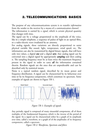
  • 1. 2. TELECOMMUNICATIONS BASICS The purpose of any telecommunications system is to transfer information from the sender to the receiver by a means of a communication channel. The information is carried by a signal, which is certain physical quantity that changes with time. The signal can be a voltage proportional to the amplitude of the voice, like in a simple telephone, a sequence of pulses of light in an optical fibre, or a radio-electric wave irradiated by an antenna. For analog signals, these variations are directly proportional to some physical variable like sound, light, temperature, wind speed, etc. The information can also be transmitted by digital binary signals, that will have only two values, a digital one and a digital zero. Any analog signal can be converted into a digital signal by appropriately sampling and then coding it. The sampling frequency must be at least twice the maximum frequency present in the signal in order to carry all the information contained therein. Random signals are the ones that are unpredictable and can be described only by statistical means. Noise is a typical random signal, described by its mean power and frequency distribution. A signal can be characterised by its behaviour over time or by its frequency components, which constitute its spectrum. Some examples of signals are shown in Figure TB 1. Figure TB 1: Examples of signals Any periodic signal is composed of many sinusoidal components, all of them multiples of the fundamental frequency, which is the inverse of the period of the signal. So a signal can be characterised either by a graph of its amplitude over time, called a waveform, or a graph of of the amplitudes of its frequency components, called a spectrum. Figure TB 2: Waveforms, Spectrum and filters
  • 2. Figure TB 2 shows how the same signal can be seen from two different perspectives. The waveform can be displayed by an instrument called an oscilloscope, while the spectrum can be displayed by what is called a Spectrum Analyzer. The spectrum distribution relays very important information about the signal and allows for the intuitive understanding of the concept of filtering of electrical signals. In the example shown, the signal is formed by the superposition of three sinusoidal components of frequency f1, f2 and f3. If we pass this signal through a device that will remove f2 and f3, the output is a pure sinusoidal at frequency f1. We call this operation “Low Pass filtering” because it removes the higher frequencies. Conversely, we can apply the signal to a “High Pass Filter”, a device that will remove f1 and f2 leaving only a sinusoidal signal at the f3 frequency. Other combinations are possible, giving rise to a variety of filters. No physical device can transmit all the infinite frequencies of the radio-electric spectrum, so every device will always perform some extent of filtering to the signal that goes through it. The bandwidth of a signal is the difference between the highest and the lowest frequency that it contains and is expressed in Hz (number of cycles per second). While travelling through the communication channel, the signal is subject to interference caused by other signals and is also affected by the electrical noise always present in any electrical or optical component. Intra-channel interference originates in the same channel as our signal. Co-channel interference is due to the imperfection of the filters that will let in signals from adjacent channels. Consequently, the received signal will always be a distorted replica of the transmitted signal, from which the original information must be retrieved
  • 3. by appropriate means to combat the effect of interference and noise. Furthermore, the received signal will be subject to attenuation and delay that increase with the distance between the transmitter and the receiver. Figure TB 3: Attenuation and delay Although it is relatively simple to restore the amplitude of signal by means of an electrical amplifier, the components of the amplifier will add additional noise to the signal, so at very long distances where the received signal is feeble, the amplifier will produce a signal so garbled with noise that the information originally transmitted will no longer be retrievable. One way to address this problem consists in converting the continuous quantity carrying the information into a sequence of very simple symbols which can be easier to recognise even at great distance. For instance, the flag of a ship is a convenient way to distinguish the nationality of the ship even at distances at which the letters on the hull cannot be read. This technique has been extended to carry generalised messages by assigning different position of flags to every letter of the alphabet, in an early form of long distance telecommunications by means of digital or numeric signals. The limitation of this method is obvious; to be able to distinguish among, say, 26 symbols corresponding to each letters of the alphabet, one must be quite close to the communicating ship.
  • 4. On the other hand, if we code each letter of the alphabet in a sequence of only two symbols, these symbols can be distinguished at much longer distance, for example the dot and dashes of the telegraph system. The process of transforming a continuous analog signal into a discontinuous digital one is called Analog to Digital Conversion (ADC), and conversely we must have a Digital to Analog Converter (DAC) at the receiving end to retrieve the original information. This is the reason why most modern telecommunication systems use digital binary signals to convey all sorts of information in a more robust way. The receiver must only distinguish between two possible symbols, or in other words between two possible values of the received bit (binary digit). For instance, the CD has replaced the vinyl record, and analogue television is being replaced by digital television. Digital signals can use less bandwidth, as exemplified by the “digital dividend” currently being harnessed in many countries which consists in bandwidth that has become available thanks to the transition from analog to digital transmission in TV broadcasting. Although in the process of converting from an analog to a digital information system there is always some loss of information, we can engineer the system so as to make this loss negligible. Figure TB 4: Undersampled Image For example, in a digital camera we can choose the number of bits used to record the image. The greater the number of bits (proportional to the amount of megapixels), the better the rendering, but more memory will be used and longer time to transmit the image will be needed. So most modern communication systems deal with digital signals, although the original variable that we want to transmit might be analog, like the voice.
  • 5. It can be shown that any analog signal can be reconstructed from discrete samples if the sampling rate is at least twice as high as the highest frequency content of the signal. Figure TB 5: detection of a noisy signal Then each sample is coded in as many bits as necessary to achieve the desired amount of precision. These bits can now be efficiently stored or transmitted, since for the recovery of the information one needs to distinguish among only two states, and not among the infinite nuances of an analog signal.
  • 6. This is shown in Figure TB 5, where the original data consists of the 0 1 0 1 1 1 0 sequence. The 0's are represented as zero volts and the 1's as 1 V. As the signal moves towards the receiver, its amplitude will diminish. This effect is called "attenuation" and is shown in the figure. Likewise, there will also be a delay as the signal moves from the transmitter to the receiver, the variability in the delay of the received signal is called jitter. Attenuation, noise or jitter (or their combination) if severe enough, can cause a detection error. An amplifier can be used to overcome the attenuation, but the electrical noise always present in the system will add to the received signal. The noisy received signal is therefore quite different from the original signal, but in a digital system we can still recover the information contained by sampling the received signal at the correct time and comparing the value at the sampling time with a suitable threshold voltage. In this example the noise received signal has a peak of 1.8 V, so we might choose e threshold voltage of 1.1 V. If the received signal is above the threshold, the detector will output a digital 1, otherwise, it will output a 0. In this case we can see that because of the effect of the noise the fifth bit was erroneously detected as a zero. Transmission errors can also occur if the sampling signal period is different from that of the original data (difference in the clock rates), or if the receiver clock is not stable enough (jitter). Any physical system will have an upper limit in the frequencies that will transmit faithfully (the bandwidth of the system), higher frequencies will be blocked, so the abrupt rise and fall of the voltage will be smoothed out as the signal goes through the channel. Therefore, we must make sure that each of the elements of the system has enough bandwidth to handle the signal. On the other hand, the greater the bandwidth of the receiver system, the greater the amount of the noise that will affect the received signal. Modulation The robustness of the digital signal is also exemplified by the fact that it was chosen for the first trials of radio transmission. Marconi showed the feasibility of long distance transmission, but pretty soon realised that there was a need to share the medium among different users.
  • 7. This was achieved by assigning different carrier frequencies which were modulated by each user’s message. Modulation is a scheme to modify the amplitude, frequency or phase of the carrier according with the information one wants to transmit. The original information is retrieved at destination by the corresponding demodulation of the received signal. Figure TB 6: Sinusoidal Carrier Signal Figure TB 6 shows a carrier signal with Amplitude A, phase θ, and frequency fo which is the reciprocal of the period T. The combination of different modulation schemes has resulted in a plethora of modulation techniques depending on which aspect one wants to optimise: robustness against noise, amount of information transmitted per second (capacity of the link in bits/second) or spectral efficiency (number of bits/s per Hertz). For instance, BPSK -Binary Phase Shift Keying- is a very robust modulation technique but transmits only one bit per symbol, while 256 QAM -Quaternary Amplitude Modulation- will carry 8 bits per symbol, thus multiplying by a factor of eight the amount of information transmitted per second, but to correctly distinguish amongst the 256 symbols transmitted, the received signal must be very strong as compared with the noise (a very high S/N -Signal/Noise ratio- is required). The ultimate measure of quality in digital transmission is the BER -Bit Error Rate- which corresponds to the fraction of erroneously decoded bits.
  • 8. Typical values of BER range between 10-3 and 10-9 . The modulation also allows us to choose which range of frequency we want to use for a given transmission. All frequencies are not created equal and the choice of the carrier frequency is determined by legal, commercial and technical constraints. Multiplexing and duplexing In general, the sharing of a channel among different users is called multiplexing. This is shown in Figure TB 7. Assigning different carrier frequencies to different users is called FDMA -Frequency Division Multiple Access-. An alternative technique consists in assigning different time slots to different users, in what is known as TDMA -Time Division Multiple Access-, or even different codes in CDMA -Code Division Multiple Access- where the different users are recognised at the receiver by the particular mathematical code assigned to them. See Figure TB 8. By using two or more antennas simultaneously, one can take advantage of the different amount of fading introduced in the different paths to the receiver establishing a difference among users in what is known as SDMA - Space Division Multiple Access-, a technique employed in the MIMO -Multiple Input,Multiple Output- systems that have gained popularity recently.
  • 9. Figure TB 8: Medium Sharing techniques Most communication systems transmit information in both directions, for instance from the Base Station to the subscriber in what is called the downlink, and from the subscriber to the base station in the uplink. To accomplish this, the channel must be shared between the two directions giving rise respectively to FDD -Frequency Division Duplexing- and TDD -Time Division Duplexing-. Conclusions The communication system must overcome the noise and interference to deliver a suitable replica of the signal to the receiver.
  • 10. The capacity of the communication channel in bits/second is proportional to the bandwidth in Hz and to the logarithm of the S/N ratio. Modulation is used to adapt the signal to the channel and to allow several signals to share the same channel. Higher order modulation schemes allow for a higher transmission rate, but require higher S/N ratio. The channel can be shared by several users that occupy different frequencies, different time slots, different codes or by taking advantage of different propagation characteristics in what is called spatial multiplexing. For more information and slides covering this topic please visit http://wtkit.org/groups/wtkit/wiki/820cb/download_page.html