DURMA Catalogue 2
•
2 j'aime•2,345 vues

Rolling machine Band saw Iron worker Profile Bender Notching machine

Recommandé
Contenu connexe
Tendances
Tendances (20)
Similaire à DURMA Catalogue 2
Similaire à DURMA Catalogue 2 (20)
Dernier
Dernier (20)
DURMA Catalogue 2
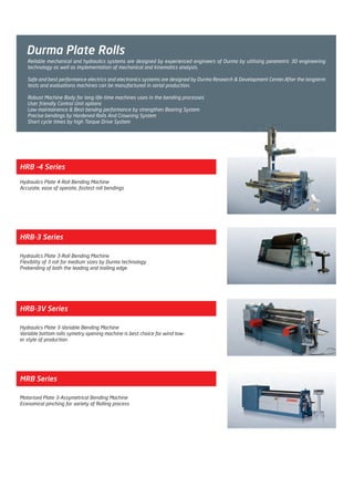
- 1. Durma Plate Rolls HRB -4 Series Hydraulics Plate 4-Roll Bending Machine Accurate, ease of operate, fastest roll bendings HRB-3V Series Hydraulics Plate 3-Variable Bending Machine Variable bottom rolls symetry opening machine is best choice for wind tow- er style of production HRB-3 Series Hydraulics Plate 3-Roll Bending Machine Flexiblity of 3 roll for medium sizes by Durma technology Prebending of both the leading and trailing edge MRB Series Motorised Plate 3-Assymetrical Bending Machine Economical pinching for variety of Rolling process Reliable mechanical and hydraulics systems are designed by experienced engineers of Durma by utilising parametric 3D engineering technology as well as implementation of mechanical and kinematics analysis. Safe and best performance electrics and electronics systems are designed by Durma Research & Development Center.After the longterm tests and evaluations machines can be manufactured in serial production. Robust Machine Body for long life-time machines uses in the bending processes User friendly Control Unit options Low maintainence & Best bendng performance by strengthen Bearing System Precise bendings by Hardened Rolls And Crowning System Short cycle times by high Torque Drive System Untitled-6 3Untitled-6 3 10/17/11 4:10 PM10/17/11 4:10 PM Process CyanProcess CyanProcess MagentaProcess MagentaProcess YellowProcess YellowProcess BlackProcess Black
- 2. HRB-4 SERIES Untitled-6 4Untitled-6 4 10/17/11 4:10 PM10/17/11 4:10 PM Process CyanProcess CyanProcess MagentaProcess MagentaProcess YellowProcess YellowProcess BlackProcess Black
- 3. Accurate, ease of operate, fastest roll bendings Flat zone of the sheet edges is minimised Pre-bending, conical bending and ellipse bending can be done easily Double pre-bends (both ends) in one pass Hydraulic and electrical systems have been safeguarded from overloads and require minimum maintenance. Hydraulic and electrical components are modular and designed according to world standards. The sheet is controlled by tightening of top and bottom rolls Most suitable bending operation for CNC applications. More efficient for cycle times User friendly operations without dependence to operator competence. Untitled-6 5Untitled-6 5 10/17/11 4:11 PM10/17/11 4:11 PM Process CyanProcess CyanProcess MagentaProcess MagentaProcess YellowProcess YellowProcess BlackProcess Black
- 4. Robust Machine Body Planetary Swing Rolls System Strengthen Bearing System Synchronized Rolls System HRB-4 Series Features Machine body is strengthen and lowered to minimise the twists and deformation. Machine body, frame and steel bar connections are stres relieved after the welding operation. Rolls are guided with spherical roller bearings and bronze housings. Guiding system requires less lubrication and keeps it precision in long term. Bottom roll tightens different thickness of sheets without deformation and taking to the consideration of its paralelism by hydraulic adjustable pressure torsion bar. Side rolls are guided by swing beds which allows them to act as 2 independent axes moving on curve shape orbits.Side rolls are approaches to the top roll on curve movement which allows to get perfect prebendings as well as spring back minimisation. (Rectilinear Rolls System designed for top roll dia ≥460mm) Untitled-6 6Untitled-6 6 10/17/11 4:11 PM10/17/11 4:11 PM Process CyanProcess CyanProcess MagentaProcess MagentaProcess YellowProcess YellowProcess BlackProcess Black
- 5. Hardened Rolls And Crowning System Conical Bending System High Torque Drive System Highly durable carbon steel (C45) rolls are machined by CNC Lathes with high precision without creating notch effect. Working surfaces of the rolls are induction hardened to HRC 54±2 Rolls are machined as crowning shape to compansate the deflactions on the rolls during the bending. By its high torque, Durma machines bend the sheet with less steps. Top and bottom rolls powered by planatery reducer, hydraulic motor and gear system. Strong Hydraulic Brake system does not allow the sheet to slip back Pressure safety valves are protecting the hydromotor and other components from overloads and peak pressures. By strong body and angular bottom and side rolls, wide angle & small diameter conical parts are easily bend. While machines in the market is bending conical bendings of 3 times of top roll,Durma HRB-4 machines can bend conical bending of 1.5 times easily. 2-4 Drive Top roll Ø 140mm – 430mm 4-4 Drive Top roll Ø 460mm – 1070mm Untitled-6 7Untitled-6 7 10/17/11 4:11 PM10/17/11 4:11 PM Process CyanProcess CyanProcess MagentaProcess MagentaProcess YellowProcess YellowProcess BlackProcess Black
- 6. Control Units Ensures the machine's bottom and side rollers’ synchronous operation. This process is provided via the PLC with 6-axis control and touch screen operator panel. Bending up to 5 steps of the program, is ease of use and saves time. İn addition to the Digital readout control system, In teaching mode for the operator to bend all the steps are recorded respectively. In automatic mode all recorded movements are repeated, respectively by the machine. NC control system has the capacity to save 70 programs consisting of Max 100-steps. CNC control system, in addition to the NC control system with its graphical control system allows the bending done step by step or automatically calculating the bendind steps without the need for operator skill. Due to ready bending shapes polisentrik bending and twisting like an ellipse, is also easily done CNC Control Digital readout NC Control Untitled-6 8Untitled-6 8 10/17/11 4:11 PM10/17/11 4:11 PM Process CyanProcess CyanProcess MagentaProcess MagentaProcess YellowProcess YellowProcess BlackProcess Black
- 7. Hydraulic System Machine movements are trigerred by hydraulic components. The precision on the all axes are acquired by world leader valves’ high speed response ability. And pressure safety valves used against peak pressures and overload, provides protection for motors and other components. Electrical and Electronic System Electrial system designed compatible with CE safety regulations. The system consists of well known electrical components .The system is protected by current overloadings for its components’, powersupplies, electronics and motors. Top Support System In large-scale bend it ensures internal support in the vertical direction. Untitled-6 9Untitled-6 9 10/17/11 4:11 PM10/17/11 4:11 PM Process CyanProcess CyanProcess MagentaProcess MagentaProcess YellowProcess YellowProcess BlackProcess Black
- 8. In large-scale bend, it ensures support for the machine from both sides from the bottom. The rip fence systems, hydraulically separated and controlled from the operator panel can be added to the machine as an option. Side Supports System Automatic Bending Loading Unloading System pport for the machine from ip fence systems, hydraulically e operator panel can be added to Untitled-6 10Untitled-6 10 10/17/11 4:11 PM10/17/11 4:11 PM Process CyanProcess CyanProcess MagentaProcess MagentaProcess YellowProcess YellowProcess BlackProcess Black
- 9. STANDARD EQUIPMENTS CE-Norm for EU Control unit with digital readout Conical bending Induction hardened rolls Side rolls positioning from electronic synchronize PLC Bottom roll rigid mechanic synchronized Stress relieved steel contruction body Rolls seated with bearings Top roll hydraulic opening device Bottom and top rolls hydraulic motor driven and planetary gear box Side rolls hydramotor, diameter 360 and above gear box plus hydramotor Electrical and hydraulic protection against overloads Hydraulic pressure adjustable bottom rools All axis positioning with adjustable speed at CNC machines HRB-4 OPTIONAL EQUIPMENTS NC Control Unit CNC Control Unit - Color - graphic Control Polished Rolls Variable speed control Oil Coolant Side supports at both side Vertical support crane system (mechanical or hydraulics) Changeable top Roll for smaller diameters Longer rolls for profile bending Welding possibility on the machine Preparation for Vertical support crane system Material feeding table Special applications for Wind-tower production Untitled-6 11Untitled-6 11 10/17/11 4:11 PM10/17/11 4:11 PM Process CyanProcess CyanProcess MagentaProcess MagentaProcess YellowProcess YellowProcess BlackProcess Black
- 10. HRB-4 HRB-4 1507 HRB-4 2006 HRB-4 2008 HRB-4 2010 HRB-4 2013 HRB-4 2016 HRB-4 2020 HRB-4 2025 HRB-4 2030 HRB-4 2035 HRB-4 2040 HRB-4 2065 HRB-4 2506 HRB-4 2508 HRB-4 2510 HRB-4 2513 HRB-4 2516 HRB-4 2520 HRB-4 2525 HRB-4 3006 HRB-4 3008 HRB-4 3010 HRB-4 3013 HRB-4 3016 HRB-4 3020 HRB-4 3025 HRB-4 3030 HRB-4 3035 HRB-4 3040 HRB-4 3050 * HRB-4 3065 * HRB-4 3085 * HRB-4 3160 * HRB-4 4008 HRB-4 4013 HRB-4 4016 HRB-4 4020 HRB-4 4035 * 1550 2050 2050 2050 2050 2050 2050 2050 2050 2050 2050 2050 2550 2550 2550 2550 2550 2550 2550 3100 3100 3100 3100 3100 3100 3100 3100 3100 3100 3100 3100 3100 3100 4100 4100 4100 4100 4100 5 4 6 8 10 13 16 20 25 30 35 50 4 6 8 10 13 16 20 4 6 8 10 13 16 20 25 30 35 40 50 70 140 6 10 13 16 30 7 6 8 10 13 16 20 25 30 35 40 65 6 8 10 13 16 20 25 6 8 10 13 16 20 25 30 35 40 50 65 85 160 8 13 16 20 35 8 7 10 12 15 18 22 28 33 38 44 70 7 10 12 15 18 22 28 7 10 12 15 18 22 28 33 38 44 55 70 90 168 10 15 18 22 38 170 170 200 210 230 270 300 330 360 400 430 490 200 210 230 270 300 330 360 210 230 270 300 330 360 400 430 460 490 500 650 760 1070 300 360 400 430 500 150 150 190 190 210 250 270 300 330 370 400 490 190 190 210 250 270 300 330 190 210 250 270 300 330 370 400 460 490 500 610 720 1020 270 330 370 400 500 140 140 170 180 190 220 220 240 270 290 320 390 170 180 190 220 220 240 270 180 190 220 220 240 270 290 320 370 370 410 500 600 870 220 270 290 320 410 15 15 30 30 30 50 50 50 60 65 70 100 30 30 30 50 50 50 60 30 30 50 50 50 60 65 70 90 100 100 125 160 280 50 60 65 70 100 3040 3540 3830 3830 3830 4260 4260 4260 4510 4510 4510 5250 4330 4330 4330 4760 4760 4760 5010 4880 4880 5310 5310 5310 5560 5560 5560 6200 6300 6400 6350 7500 8500 6310 6560 6560 6560 7400 970 970 1160 1160 1160 1660 1660 1660 2060 2060 2060 2300 1160 1160 1160 1660 1660 1660 2060 1160 1160 1660 1660 1660 2060 2060 2060 2300 2300 2350 3240 3600 5300 1660 2060 2060 2060 2350 1140 1140 1180 1180 1180 1590 1590 1590 2050 2050 2050 2600 1180 1180 1180 1590 1590 1590 2050 1180 1180 1590 1590 1590 2050 2050 2050 2530 2600 2650 3660 3950 5500 1590 2050 2050 2050 2650 865 865 840 835 825 1155 1140 1125 1510 1490 1475 1865 840 835 825 1155 1140 1125 1510 835 825 1155 1140 1125 1510 1490 1475 1875 1865 1840 2825 3000 4190 1140 1510 1490 1475 1840 2600 3030 4730 4940 5280 9600 10000 10800 15700 16800 17900 30000 5240 5500 5920 10600 11100 12100 17500 6200 6700 11800 12300 13400 19000 20800 22600 34000 40000 45000 70000 90000 230000 14600 22400 24600 27000 54000 5,5 5,5 7,5 7,5 11 15 18,5 22 30 37 45 60 7,5 7,5 11 15 18,5 22 22 7,5 11 11 15 18,5 22 30 37 44 52 60 74 110 300 11 18,5 22 30 52 Bending Length L(mm) Pre- Bending Capacities s(mm) Ødx1,5 Ødx3 "Min. Int. Dia Ø Dmin" Ødx5 Bending Capacities S(mm) Bending Capacities S(mm) Top Roll ød(mm) Bottom Roll ød(mm) Side Rolls ød(mm) Max. Pass Through A(mm) Length U(mm) Width G(mm) Height Y(mm) Working Height C(mm) Weight kg Motor Power (kW) For 240 N/mm² yield point material * Ø Dmin= Ødx2 (Pre Bending) ; Ødx4 (Bending) Conical bending capacity can be taken half of above values. Untitled-6 12Untitled-6 12 10/17/11 4:11 PM10/17/11 4:11 PM Process CyanProcess CyanProcess MagentaProcess MagentaProcess YellowProcess YellowProcess BlackProcess Black
- 11. HRB-3 SERIES Flexible roller especially for medium thick Cost effective solutions for big diameters Wide working range Excellence of cone bends Good value for precision and reliability All 3 rolls are driven with superior roll torque and speed Untitled-6 13Untitled-6 13 10/17/11 4:11 PM10/17/11 4:11 PM Process CyanProcess CyanProcess MagentaProcess MagentaProcess YellowProcess YellowProcess BlackProcess Black
- 12. STANDARD EQUIPMENTS CE-Norm for EU Control unit with digital readout Conical bending Induction hardened rolls Side rolls positioning from electronic synchronize PLC Bottom roll rigid mechanic synchronized Stress relieved steel contruction body Rolls seated with bearings Top roll hydraulic opening device Top rolls hydraulic motor driven and planetary gear box Side rolls hydramotor, diameter 360 and above gear box plus hydramotor Electrical and hydraulic protection against overloads HRB-3 OPTIONAL EQUIPMENTS Polished Rolls Variable speed control Oil Coolant Side supports at both side Vertical support crane system (mechanical or hydraulics) Material feeding table Changeable top Roll for smaller diameters Longer rolls for profile bending Welding possibility on the machine Preparation for Vertical support crane system HRB-3 HRB-3 2006 HRB-3 2008 HRB-3 2010 HRB-3 2013 HRB-3 2016 HRB-3 2020 HRB-3 2025 HRB-3 2030 HRB-3 2506 HRB-3 2508 HRB-3 2510 HRB-3 2513 HRB-3 2516 HRB-3 2520 HRB-3 2525 HRB-3 3006 HRB-3 3008 HRB-3 3010 HRB-3 3013 HRB-3 3016 HRB-3 3020 HRB-3 3025 HRB-3 3030 HRB-3 4008 HRB-3 4013 HRB-3 4016 2050 2050 2050 2050 2050 2050 2050 2050 2550 2550 2550 2550 2550 2550 2550 3100 3100 3100 3100 3100 3100 3100 3100 4100 4100 4100 4 6 8 10 13 16 20 25 4 6 8 10 13 16 20 4 6 8 10 13 16 20 25 6 10 13 6 8 10 13 16 20 25 30 6 8 10 13 16 20 25 6 8 10 13 16 20 25 30 8 13 16 185 200 220 230 270 300 330 360 200 220 230 270 300 330 360 220 230 270 300 330 360 410 430 300 360 410 165 180 200 210 250 270 290 320 180 200 210 250 270 290 320 200 210 250 270 290 320 380 390 270 320 380 70 70 55 80 100 100 100 100 70 55 80 100 100 100 100 55 80 100 100 100 100 70 100 100 100 70 3850 3850 3950 3950 4150 4150 4350 4350 3850 4450 4450 4650 4650 4850 4850 5000 5000 5200 5200 5400 5400 6000 6000 6200 6400 7000 1300 1300 1400 1400 1650 1650 1900 1900 1300 1400 1400 1650 1650 1900 1900 1400 1400 1650 1650 1900 1900 2100 2200 1650 1900 2100 1150 1150 1150 1500 1400 1400 1700 1700 1150 1150 1500 1400 1400 1700 1700 1150 1500 1400 1400 1700 1700 1900 2000 1400 1700 1900 810 820 820 900 980 1030 1075 1235 820 820 900 980 1030 1075 1235 820 900 980 1030 1075 1235 1240 1430 1030 1235 1240 2500 3300 4000 4800 6000 7200 9300 10000 3800 4500 5500 6700 8000 10400 11500 5000 6000 7500 9000 11800 12500 17000 21000 11000 18000 22000 5.5 7.5 7.5 11 15 18.5 22 30 7.5 7.5 11 15 18.5 22 22 7.5 7.5 11 15 18.5 22 30 37 11 18.5 22 Bending Length L(mm) Pre- Bending Capacities s(mm) Ødx1,5 Ødx3 Min. Int. Dia Ø Dmin Bending Capacities S(mm) Top Roll ød(mm) Side Rolls ød(mm) Max. Pass Through A(mm) Length U(mm) Width G(mm) Height Y(mm) Working Height C(mm) Weight kg Motor Power (kW) For 240 N/mm² yield point material * Ø Dmin= Ødx2 (Pre Bending) ; Ødx4 (Bending) Conical bending capacity can be taken half of above values. Untitled-6 14Untitled-6 14 10/17/11 4:11 PM10/17/11 4:11 PM Process CyanProcess CyanProcess MagentaProcess MagentaProcess YellowProcess YellowProcess BlackProcess Black
- 13. HRB-3V SERIES 3 rolls variable axis plate roll bending machines are more precise,faster, more productive and safer plate roll benders by its user friendly operations without dependence to operator competence. They are suitable for medium and thick plate bending. Unlike the usual cylinder machines, the lower rolls move horizontally to right and left and the upper roll moves up and down. As at 4 roll Machines steel load parallel to the floor so machine pit can be at machine working level With the system functioning upper roller trainer can be used as a traditional press. Forming operations and calibration of the welded tubes finishes. The sheet is controlled by tightening of top and bottom rolls.This operation does not allow the sheet is skid and fall down.The machine can also be installed below the ground. Please ask for detail specifications Untitled-6 15Untitled-6 15 10/17/11 4:11 PM10/17/11 4:11 PM Process CyanProcess CyanProcess MagentaProcess MagentaProcess YellowProcess YellowProcess BlackProcess Black
- 14. MRB-S SERIES Especially for thinner sheets with small lot sizes Easy prebending thanks to top & bottom rolls tighten the workpiece Cost-oriented solutions for small and medium enterprises Wide range of industrial usage MOTORISED ASSYMETRICAL 3 ROLL MACHINES MRB-S Series Unit 1506 2005 2006 2504 2506 2508 3004 3006 Bending length Bending capacity Pre bending Top roll Ø Motor power Length Height Width Weight mm mm mm mm kW mm mm mm kg 1530 6 4 150 4 3100 1120 1020 2100 2030 5 4 160 4 3600 1120 1020 2300 2030 6 5 170 4 3600 1120 1020 2400 2530 4 3 170 4 4100 1120 1020 2700 2530 6 4 190 5,5 4250 1200 1150 3750 2530 8 6 220 5,5 4250 1200 1150 4430 3030 4 2 180 4 4600 1120 1020 4250 3030 6 4 220 5,5 4750 1200 1150 4920 STANDARD EQUIPMENTS CE Conical bending Motorised back roll Top and bottom rolls gear driven Pendant command panel SAE 1050 steel rolls Induction hardened rolls Stress relieved steel construction Support on 2,5 and 3 m machines Brake system for precise bendings OPTIONAL EQUIPMENTS Digital readout Motorised bottom roll tightening Ground rolls Roll extention for profile bending Special rolls for profile bending Untitled-6 16Untitled-6 16 10/17/11 4:11 PM10/17/11 4:11 PM Process CyanProcess CyanProcess MagentaProcess MagentaProcess YellowProcess YellowProcess BlackProcess Black
- 15. MRB SERIES Bending length Bending capacity Pre bending Top roll Ø Motor power Length Height Width Weight MRB Series 1030 4 3 110 2.2 1900 1120 940 1195 1280 4 3 120 2.2 2150 1120 940 1345 1530 3 2 110 2.2 2400 1120 940 1388 mm mm mm mm kW mm mm mm kg Unit 1004 1204 1503 1530 4 3 130 2.2 2400 1120 940 1425 1504 2030 4 2.5 140 2.2 2900 1120 940 1565 2004 STANDARD EQUIPMENTS CE Conical Bending Bottom and back rolls manuel Top and bottom rolls powered by electric motor,gearbox and gear drive Pendant control panel Cast Iron frame Precise bending with motor brake OPTIONAL EQUIPMENTS Digital readout Motorised botttom roll Motorised back roll Hardened rolls Ground rolls Untitled-6 17Untitled-6 17 10/17/11 4:11 PM10/17/11 4:11 PM Process CyanProcess CyanProcess MagentaProcess MagentaProcess YellowProcess YellowProcess BlackProcess Black
- 16. MRB-E SERIES RB SERIES Bending length Bending capacity Pre bending Top roll Ø Motor power Length Height Width Weight MRB E Series 1030 1 0,8 56 0,75 1750 1100 840 280 1030 2 1,2 75 0,75 1750 1135 840 385 1030 3 2 90 1,5 1750 1135 840 440 1280 2 1,2 75 1,5 2000 1135 840 455 1280 3 2 95 1,5 2000 1135 840 555 mm mm mm mm kW mm mm mm kg Unit 1001 1002 1003 1202 1203 1530 2,5 1,5 95 1,5 2250 1135 840 630 2030 1,5 0,8 90 1,5 2750 1135 840 680 1525 2015 STANDARD EQUIPMENTS CE Conical bending Bottom and back rolls manual Cast Iron frame SAE 1050 steel rolls Rode bending channels on bottom and back rolls Pendant foot pedal Emergency stop OPTIONAL EQUIPMENTS Hardened rolls Ground rolls Bending length Bending capacity Pre bending Top roll Ø Length Height Width Weight RB Series 1030 1 0,8 56 1500 1100 520 220 1030 2 1,2 75 1750 1135 520 370 1030 3 2 90 1750 1135 520 410 1280 2 1,2 75 2000 1135 520 430 1280 2,5 1,5 90 2000 1135 520 490 1280 3 2 95 2000 1135 50 515 mm mm mm mm mm mm mm kg Unit 1001 1002 1003 1202 1225 1203 1530 2,5 1,5 95 2250 1135 520 595 1525 STANDARD EQUIPMENTS CE Conical bending Casting frame SAE 1050 steel rolls Rode bending channels on bottom and back rolls OPTIONAL EQUIPMENTS Hardened rolls Ground rolls 1525 Untitled-6 18Untitled-6 18 10/17/11 4:11 PM10/17/11 4:11 PM Process CyanProcess CyanProcess MagentaProcess MagentaProcess YellowProcess YellowProcess BlackProcess Black
- 17. Durma Profile Bending Machines PBM Series Motorised Profile Bending Machines PBH Series Hydraulic Profile Bending Machines Robust machine frame is rugged steel construction, machined after the welding for rigidity. Precise bending by large shaft diameters and bearings also minimizes deflection Longlife of machine by strong frame and world class components Short cycle times by high drive torque and speed Minimised straight edge by hydraulic adjustments Low energy and maintainence costs by Friction free planetary swing guides Powerful guide rolls Untitled-6 19Untitled-6 19 10/17/11 4:12 PM10/17/11 4:12 PM Process CyanProcess CyanProcess MagentaProcess MagentaProcess YellowProcess YellowProcess BlackProcess Black
- 18. PBM 30 - PBM 50 - PBH 45 PBM 30 - 50 Standard Equipment CE 1 set standard hardened and ground rolls Mechanic side supports Horizontal & Vertical working feature Foot pedal with Emergency button Bottom rolls driven by motor & gearbox Cast iron body Optionals Special support for angle irons Bar twist device Digital readout Mono phase motor Special rolls ( Pipe,profile, angle iron ) PBH 45 Standard Equipment CE 1 set standard hardened and ground rolls made by special steel Mechanic side supports Horizantal & Vertical working feature Movable command panel seperate from the machine All rolls driven by motor & gearbox Top roll hydraulic movement up and down Top roll with digital readout Brake motor Cast iron body Optionals Special support for angle irons Special rolls ( Pipe,profile, angle iron ) NC control Untitled-6 20Untitled-6 20 10/17/11 4:12 PM10/17/11 4:12 PM Process CyanProcess CyanProcess MagentaProcess MagentaProcess YellowProcess YellowProcess BlackProcess Black
- 19. Untitled-6 21Untitled-6 21 10/17/11 4:12 PM10/17/11 4:12 PM Process CyanProcess CyanProcess MagentaProcess MagentaProcess YellowProcess YellowProcess BlackProcess Black
- 20. PBH 60 PBH 80 - 100 Standard Equipment CE Digital readout ( X,Y axis) Rolls are planetary gear box and motor driven 1 set standard hardened and ground rolls made by special steel 3 axis hardened side supports Side supports are suitable for angle iron bending 3 axis side supports Front-Back ;Up- Down;:Left-Right manual adjustable (Z,U,C axis) Movable command panel seperate from the machine Horizontal working feature Stress relieved steel construction body Electrical and hydraulic protection against overloads Optionals Hydraulic Z axis Full hydraulic 3 axis side supports ( Z,U,C axis) Digital readout ( Z,U,C) Axis NC control system CNC control system Variable turning speed Tie Bar For Rolls Special rolls ( Pipe,profile, angle iron ) Standard Equipment CE Hydraulic Z axis Digital readout ( X,Y axis) All rolls driven by planetary gear box and hydramotor 1 set standard hardened and ground rolls made by special steel 3 axis side supports Z Front-Back:Hydraulic ;U :Up-Down&C : Left-Right manual Side supports are suitable for angle iron bending Movable command panel seperate from the machine Horizontal working feature Stress relieved steel construction body Electrical and hydraulic protection against overloads Optionals Full hydraulic 3 axis side supports ( standard Z +U,C axis) Digital readout ( Z,U,C) Axis NC control system CNC control system Variable turning speed Tie Bar For Rolls Special rolls ( Pipe,profile, angle iron ) Untitled-6 22Untitled-6 22 10/17/11 4:12 PM10/17/11 4:12 PM Process CyanProcess CyanProcess MagentaProcess MagentaProcess YellowProcess YellowProcess BlackProcess Black
- 21. Untitled-6 23Untitled-6 23 10/17/11 4:12 PM10/17/11 4:12 PM Process CyanProcess CyanProcess MagentaProcess MagentaProcess YellowProcess YellowProcess BlackProcess Black
- 22. Standard Equipment CE Digital readout ( X,Y axis) All rolls driven by planetary gear box and hydramotor ( PBH 125 ) All rolls 3 different planetary gear box and hydramotor driven ( PBH 180 to 360) Full hydraulic 3 axis ( Z,U,C) side supports Movable command panel seperate from the machine Horizontal working feature ( PBH 125 can also be operated in vertical position) Stress relieved stell construction body Electrical and hydraulic protection against overloads 1 set standard hardened and ground rolls made by special steel Optionals Digital readout ( Z,U,C) Axis NC control system CNC control system Adjustable turning speed Special aparatus to prevent deformation on U-I-H bending Special rolls ( Pipe,profile, angle iron ) PBH 125 - 360 Untitled-6 24Untitled-6 24 10/17/11 4:12 PM10/17/11 4:12 PM Process CyanProcess CyanProcess MagentaProcess MagentaProcess YellowProcess YellowProcess BlackProcess Black
- 23. Untitled-6 25Untitled-6 25 10/17/11 4:12 PM10/17/11 4:12 PM Process CyanProcess CyanProcess MagentaProcess MagentaProcess YellowProcess YellowProcess BlackProcess Black
- 24. PBH 300 Untitled-6 26Untitled-6 26 10/17/11 4:12 PM10/17/11 4:12 PM Process CyanProcess CyanProcess MagentaProcess MagentaProcess YellowProcess YellowProcess BlackProcess Black
- 25. IW Series Iron Worker Combined and convenient metal working solution for variety of processes P Series Punch Cost effective punching solution for every thicknesses Multi Punch Multiple punching head and CNC, machine offers productivity and ease of operation. Multi Punch Line Multiple punching head and CNC, machine offers productivity and ease of operation for huge sheet punching. MULTI - P Series MULTI - P Line Untitled-6 27Untitled-6 27 10/17/11 4:12 PM10/17/11 4:12 PM Process CyanProcess CyanProcess MagentaProcess MagentaProcess YellowProcess YellowProcess BlackProcess Black
- 26. Untitled-6 28Untitled-6 28 10/17/11 4:12 PM10/17/11 4:12 PM Process CyanProcess CyanProcess MagentaProcess MagentaProcess YellowProcess YellowProcess BlackProcess Black
- 27. IW SERIES The DURMA Hydraulic Ironworkers are designed with multi-functions to save labor, time energy and cost. DURMA Ironworkers are well engineered, maximum efficiency and long life is guaranteed by latest manufacturing methods. These universal machines are supplied with Standard tooling including repetition support tables at punch, shear and notch stations and with easily adjusted hold downs at all five work stations. Each work station is equipped with specially designed hold downs to ensure safety while providing precision and easy use. DURMA Ironworkers stand for reliability, productivity and accuracy. Untitled-6 29Untitled-6 29 10/17/11 4:12 PM10/17/11 4:12 PM Process CyanProcess CyanProcess MagentaProcess MagentaProcess YellowProcess YellowProcess BlackProcess Black
- 28. IW Series Features The punch station is designed with versatility in mind. The station of the bolster plate, makes it possible to perform a wide range of punching. This includes the punching of flat bar, flange, angle, and channel. The station comes standard with quick change punch and die holders, as well as a swing away stripper. Also included are x & y coordinate gauge stops. This feature is useful for repetitive work. At punch station different punching diameter, pipe notching and bending with pres brake attachment can be performed. Punching Flat SteelSwing Away Stripper Press Brake Attachment Punching Channel Flangers And Angles Blades are four sided and and easily installed and rotated. An easy adjustable hold down provides for proper clamping of the material while it is being sheared. Angle Shearing Station Punching Station Different Dimension Punch & Dies Untitled-6 30Untitled-6 30 10/17/11 4:12 PM10/17/11 4:12 PM Process CyanProcess CyanProcess MagentaProcess MagentaProcess YellowProcess YellowProcess BlackProcess Black
- 29. An easily adjustable hold down ensures proper clamping of the plate. An entry feed table has adjustable guides and stops to make sure the material is accurately placed under the cutting blades. The blades are manufactured in such a way that allows cutting of a wide range of material thickness at a low rake angle and without the need for adjustment. Flat Shearing Station Bar Shearing Stations Square bar Shearing Touch and cut electrical back gauge Round bar Shearing Optional U blade Optional I & T blades Untitled-6 31Untitled-6 31 10/17/11 4:12 PM10/17/11 4:12 PM Process CyanProcess CyanProcess MagentaProcess MagentaProcess YellowProcess YellowProcess BlackProcess Black
- 30. This station comes standard with rectangular notching blades which allow side notching, therefore allowing notching of unlimited widths. Vee notching blades can easily be installed, and are available as an option. Other optional devices include tube notching. It is also possible to convert this station to a punching or bending station. A large feed and worktable with gauging stops helps speed up repetitive type work and ease material handling. Notching Stations IW 45 & IW 45 M Rectangular Notcher Triangular Notcher Option) Durma IW 45 Series Ironworkers are specially designed for high volumes and with its 5 stations enables to make efficient production. 45 tom machines have single cylinder and 5 stations can be operated by one foot pedal. Untitled-6 32Untitled-6 32 10/17/11 4:12 PM10/17/11 4:12 PM Process CyanProcess CyanProcess MagentaProcess MagentaProcess YellowProcess YellowProcess BlackProcess Black
- 31. Swing away stripper Punching Station Flat Shearing Station Bar Shearing Station Angle Shearing Station for IW45 M Angle Shearing Station for IW45 Notching Station Punching station has max. Capacity of 27x13 & 18x18 Punching flat steel 200x15 mm. & 300x12 mm. Flat steel cutting capacity This station allows to cut special bars with special blades such as round, square, channels and many other special profiles In this station standard rectangular notching and with special blade triangular notching can be performed At angle shear station with Z shape apparatus, it is possible to make miter shear on angle bars Untitled-6 33Untitled-6 33 10/17/11 4:12 PM10/17/11 4:12 PM Process CyanProcess CyanProcess MagentaProcess MagentaProcess YellowProcess YellowProcess BlackProcess Black
- 32. Round Bar Shear Square Bar Shear Round Bar Shear Square Bar Shear U - Profil Shear T - Profil Shear I - Profil Shear Material thickness Rectangular Notcher (width) Rectangular Notcher (depth) Vee-Notcher (Side x Side x T) Triangular notching material tickness Triangular notching width V90 Triangular notching depth Motorpower Oil Capacity Weight Machine dimensions (L x W x H) Working Height At 90° Shearing At 90° Shearing width slight deformation At 45° Miter Shearing IW PUNCHING FLAT SHEARING BAR SHEARING NOTCHING GENERAL INFORMATION ANGLE SHEARING IW 36 IW 45 IW 45 - M Punching Pressure Punch Capacity(Diameter x Thickness) Throat Depth Stroke lenght Cycles /Min. (15 mm stroke) Cycles /Min. (20 mm stroke) Table Size (W x D) Largest Hole Single Vee Press Brake (W x T) Multi-Vee Press Brake (W x T) Pipe Notching 1 ) A min-max for NPU Maximum S - Maximum ØD ( Accor DIN 997) 2 ) A min-max for NPU Maximum S - Maximum ØD ( Accor DIN 997) Flat Bar (max. thickness) Flat Bar (max. width) Blade Length Angle Flange Trim Round Bar Shear Square Bar Shear ton mm mm mm quat. quat. mm mm mm mm inch mm mm mm mm mm mm mm mm mm mm mm mm mm mm mm mm mm mm mm mm mm mm mm mm mm mm mm kw lt kg mm mm 36 Ø27x10 Ø16x16 160 28 24 - 450x220 - - - - - - - - 200x13 350x6 356 80x80x10 30 25 80x80x10 - 50x50x6 - - 35 30 - - - 3 33 630 1200x1470x1390 990 - - - - - - - 45 Ø27x13 Ø18x18 160 21 20 - 450x160 Ø100x3 - - - - - - - 200x13 300x10 305 80x80x10 - - 80x80x8 100x100x10 - 30 30 - - 100 40 100 3 33 890 1460x1400x1620 1010 7 40 50 40x40x7 4 75 75 45 Ø27x13 Ø18x18 160 21 20 - 450x160 Ø100x3 - - - - - - - 200x13 300x10 305 80x80x10 - - 80x80x8 - 60x60x6 25 22 - - 100 40 100 3 33 970 1460x1580x1450 1010 7 40 50 40x40x7 4 75 75 Flat Shearing Round Shearing Square Shearing Angle Flat Shearing ØD A s B 1 ) s ØD B A 2 ) Untitled-6 34Untitled-6 34 10/17/11 4:12 PM10/17/11 4:12 PM Process CyanProcess CyanProcess MagentaProcess MagentaProcess YellowProcess YellowProcess BlackProcess Black
- 33. IW 55/110 IW 55/110 BTD IW 80/150 IW 80/150 BTD IW 110/180 BTD IW 165/300 BTD 55 Ø40x10 Ø20x20 250 60 - 37 550x250 Ø160x2 250x10 500x5 "1/2"" - 2"" 120 - 260 10 - Ø25 100 - 240 10 - Ø25 200x20 300x15 305 60x60x8 - - 120x120x10 - 70x70x7 20-40 20-40 <20 <20 120 50 120 5,5 76 1270 1480x1800x1730 1080 10 42 90 42x42x10 6 95 95 80 Ø40x14 Ø24x24 300 70 - 38 550x300 Ø160x3 300x10 600x6 "1/2"" - 2"" 120 - 400 14 -Ø28 100 - 320 14 -Ø28 300x20 450x15 475 80x80x10 - - 130x130x13 - 70x70x7 45 45 - - 140 60 140 11 76 2260 2025x1780x2700 1195 12 52 90 52x52x12 6 125 125 110 Ø40x20 Ø28x28 610 80 - 28 550x610 Ø160x5 300x10 600x8 "1/2"" - 2"" 140 - 400 14 - Ø28 120 - 320 14 - Ø28 400x20 600x15 605 100x100x12 - - 152x152x13 - 70x70x7 50 50 - - 160 60 160 11 76 3580 2560x2550x1790 1260 13 52 90 52x52x13 6 125 125 80 Ø40x14 Ø24x24 510 70 - 38 550x510 Ø160x3 300x10 600x6 "1/2"" - 2"" 120 - 400 14 - Ø28 100 - 320 14 - Ø28 300x20 450x15 475 80x80x10 - - 130x130x13 - 70x70x7 45 45 - - 140 60 140 11 76 2530 2120x2025x1780 1195 12 52 90 52x52x12 6 125 125 165 Ø40x30 Ø34x34 610 90 - 31 750x510 Ø160x7 415x12 835x8 "1/2"" - 2"" 120-400 14 - Ø28 120 - 320 14 - Ø28 400x30 750x20 765 120x120x12 - - 205x205x18 - 70x70x7 60 60 - - 200 80 200 15 150 8070 3230x1100x2280 1110 16 58 110 58x58x16 10 125 125 55 Ø40x10 Ø20x20 510 60 - 37 550x510 Ø160x2 250x10 500x5 "1/2"" - 2"" 120 - 260 10 - Ø25 100 - 240 10 - Ø25 200x20 300x15 305 60x60x8 - - 120x120x10 - 70x70x7 20-40 20-40 <20 <20 120 50 120 5.5 76 1680 1980x1800x1730 1088 10 42 90 42x42x10 6 95 95 Untitled-6 35Untitled-6 35 10/17/11 4:12 PM10/17/11 4:12 PM Process CyanProcess CyanProcess MagentaProcess MagentaProcess YellowProcess YellowProcess BlackProcess Black
- 34. STANDARD EQUIPMENTS PUNCHING Table for punching station Durma punch&die holder 1 starting set ( Punch & Die ) Punch holder up to 28 mm (IW 45-45M) Punch holder up to 40 mm (IW 55/110-55/110 BTD- 80/150-80/150 BTD-110/180 BTD) 1m. Electrical back gauge (over 55 tons) 1m. Manual backgauge for 36 &45 to Blades for flat steel station Blades for angle cutting station Blades for round and square bar cutting station Rectangular notcher complete with down holder Table for notching station IW OPTIONAL EQUIPMENTS Illmunations (24V-220V) 1 m. Manual Back gauge ( additional) Electrical Back gauge( over 1 m.) Gress pump Special Colour Overseas special packaging PUNCHING Pedinghaus, Mubea,Kingsland punch&die holder Bending equipment ( top tool +single Vee+toolholder) 40-80 NPU punching equipment "Pipe Notching Equipment (between 1/2"" and 2"" any diameter) witouth punch&die" For pipe notching punch and dies (each set) NC control with table x=1000mm Y=350mm FLAT SHEARING Spare blades for flat shearing ANGLE SHEARING Spare blades for angle shearing BAR SHEARING Spare blades for bar shearing U,I,T profile blades NOTCHING Triangular notching system with blades Spare blades for triangular notching Spare blades for rectangular notching Untitled-6 36Untitled-6 36 10/17/11 4:12 PM10/17/11 4:12 PM Process CyanProcess CyanProcess MagentaProcess MagentaProcess YellowProcess YellowProcess BlackProcess Black
- 35. P SERIES Untitled-6 37Untitled-6 37 10/17/11 4:12 PM10/17/11 4:12 PM Process CyanProcess CyanProcess MagentaProcess MagentaProcess YellowProcess YellowProcess BlackProcess Black
- 36. Different dimension Punch & Dies The punching station comes standard with quick change punch and die holders, as well as a swing away stripper Punching channel flanges and angles Punching flat steel STANDARD EQUIPMENTS Table for punching station Durma punch&die holder 1 starting set ( Punch & Die ) Punch holder up to 28 mm (IW 45-45M) Punch holder up to 40 mm (IW 55/110-55/110 BTD- 80/150-80/150 BTD-110/180 BTD) OPTIONAL EQUIPMENTS Illmunations (24V-220V) Special Colour Overseas special packaging PUNCHING Pedinghaus, Mubea,Kingsland punch&die holder Bending equipment ( top tool +single Vee+toolholder) 40-80 NPU punching equipment "Pipe Notching Equipment (between 1/2"" and 2"" any diameter) witouth punch&die" For pipe notching punch and dies (each set) NC control with table x=1000mm Y=350mm Untitled-6 38Untitled-6 38 10/17/11 4:12 PM10/17/11 4:12 PM Process CyanProcess CyanProcess MagentaProcess MagentaProcess YellowProcess YellowProcess BlackProcess Black
- 37. MULTI P SERIESMULTI P STANDARD EQUIPMENTS Triable Punching Unit Hydraulic Holddown Siemens Control Unit Multi P Unit 80 Max Lenght of sheet, X Axis Max Widht of sheet, Y Axis Thickness of metal plate Positioning tolerance Punching Tonnage Max. Traverse speed Of X Axis Max. Traverse speed Of Y Axis Cycles / Min (20 mm Stroke) Stroke Lenght Lenght Table Widht Width Working Height Height Weight A B C D E mm mm mm mm/m ton m/min m/min quat. mm mm mm mm mm mm kg 1500 750 2 - 20 0,1 80 25 25 38 70 3755 1310 2930 1220 2240 11150 Untitled-6 39Untitled-6 39 10/17/11 4:12 PM10/17/11 4:12 PM Process CyanProcess CyanProcess MagentaProcess MagentaProcess YellowProcess YellowProcess BlackProcess Black
- 38. MULTI P LINE Automatic Light Pole Punching line with loading and unloading. Untitled-6 40Untitled-6 40 10/17/11 4:13 PM10/17/11 4:13 PM Process CyanProcess CyanProcess MagentaProcess MagentaProcess YellowProcess YellowProcess BlackProcess Black
- 39. VN - FN Series Corner Notchers with variable and fixed angle Corner Notchers have a heavy and rigit construction with a solid machined table and durable blades. MS Series Power Operated Shear All-in :Hi-Speed, Accurate, Efficient, Performance CK Series Manual Folders Economic solution for thin sheet bending. Manual Shears Economic solution for thin sheet or other material cutting. Border Machines Flexible bordering motorised or manual. KGM Series BM Series Shear & Notcher Untitled-6 41Untitled-6 41 10/17/11 4:13 PM10/17/11 4:13 PM Process CyanProcess CyanProcess MagentaProcess MagentaProcess YellowProcess YellowProcess BlackProcess Black
- 40. MS SERIES All-in : Hi-Speed, Accurate ,Efficient, Performance High performance motor-driven shear Direct drive technology provides efficient operations Speedy cutting without sacrifice from the cutting quality Productive solution for serial production Proven quality gear system & mechanical parts Sheet Hold Downs Table Top Ball Transfers The MS series is equipped with ball transfers in the table. This asists in feding the sheet as well as reducing marking on sesitive materials. A simple spring style hold down system securely holds the material in place during the shearing process. Power Operated Shear Untitled-6 42Untitled-6 42 10/17/11 4:13 PM10/17/11 4:13 PM Process CyanProcess CyanProcess MagentaProcess MagentaProcess YellowProcess YellowProcess BlackProcess Black
- 41. Thin Sheet Support System Shows SBT Support System When shearing long drop pieces of thin material up to the sheet can droop before it reaches the gauge bar,therefore making it impossible tu gauge or, at least gauge accurately. In this system support arms that are pneumatically activated support the sheet while gauging and then automatically move away for shearing after the sheet is securely clamped and gauged. This also eliminates the need to front gauge and he need for the operator or additional personnel, to manually support the sheet from the rear side of the machine, which is not only costly, but unsafe. FEATURES D-Touch 7 Large Color Touch Screen, Lcd: 7", 800 X 480 Tft Lcd Display Rapid data input Easy communication, USB Port: Usb port for user usb flash memory Ethernet: RJ-45 10/100M Operating System: Windows CE User Program and Steps: Unlimited Material Type: Unlimited Untitled-6 43Untitled-6 43 10/17/11 4:13 PM10/17/11 4:13 PM Process CyanProcess CyanProcess MagentaProcess MagentaProcess YellowProcess YellowProcess BlackProcess Black
- 42. Cutting capacity Cutting length Cutting angle Stroke per min Motor power Backgauge Range Table Width Table Height Height Width Length Weight approx MS Series 3 1350 2° 30' 35 3 550 400 850 1200 1350 1700 1100 3 2050 2° 12' 35 3 550 400 850 1200 1350 2400 1300 2,5 2550 1° 30' 35 3 550 400 850 1200 1350 2860 1400 4 2050 1° 30' 42 7.5 750 450 800 1330 2300 2550 2800 4 2550 1° 30' 42 7.5 750 450 800 1330 2300 3050 3230 4 3100 1° 30' 42 7.5 750 450 800 1330 2300 3650 3730 mm mm < 1/min. kw mm mm mm mm mm mm ~kg Unit 1303 2003 2525 2004 2504 3004 MS STANDARD EQUIPMENTS Heavy duty St 44 AI steel construction & Stress relieved frame Digital readout Easy blade gap adjustment Manual back gauge Ballscrew motorized back gauge Ball integrated front tables Finger protect Portable foot control with emergency stop button Top blades with 2 sides, Bottom blades with 2 sides Top blades with 2 sides, Bottom blades with 4 sides High performance mechanics & electronics components ( MS 1303,2003,2525) ( MS 2004,2504,3004) ( MS 2004,2504,3004) ( MS 1303,2003,2525) ( MS 2004,2504,3004) OPTIONAL EQUIPMENTS CE-Norm for EU Userfriendly CNC Touchscreen control unit - D-Touch 7 Illumination & Shadow line Ballscrew motorized back gauge Special back gauge Pneumatic thin sheet support system Sheet Support device with conveyor belt and scrap container Stacker + Alıgment Cylinder Adjustable Angle stop 0-180° add. Support Arms Special blades Holddown with Rubber Special color Overseas special packaging ( MS 2004,2504,3004) ( MS 1303,2003,2525) Untitled-6 44Untitled-6 44 10/17/11 4:13 PM10/17/11 4:13 PM Process CyanProcess CyanProcess MagentaProcess MagentaProcess YellowProcess YellowProcess BlackProcess Black
- 43. FN - VN SERIES Durma Corner Notchers have a rigit construction with a solid machined table. T-Slots have been machined in the table for fast and accurate positioning of gauge stops and protractor guides. The operator can adjust the angle of notch from 30 to 140 degrees easily and quickly via hand viels wheels located on each side of the machine. The automatic blade adjustment feature assures high quality cuts on varied thickness and types of material.There are three upper and four lower hydraulics cylinders that create a rigid structure for accurate for and repeatable notching. The measuring scales have been positioned below the work service to prevent wearing of dimensional readouts over time. FN-VN Unit FN 2004 VN 2004 VN 2006 Cutting Capacity Cutting Length Cutting Angle Stroke per min. Motor Power Working pressure Oil Capacity Height Width Length Weight Sound Strength ( unloaded ) Sound Strength ( loaded ) Paint Number : White Grey Orange mm mm < 1 / min ( max ) Strok : 8 mm Kw bar lt mm mm mm kg dBA dBA - - - 200 X 200 90° 34 4 180 2610 psi 36 1100 950 850 ~ 550 60 62 RAL 7032 RAL 7039 RAL 2001 4 200 X 200 from 30° to 140° 28 4 180 2610 PSI 50 1300 1050 900 ~ 950 66 77 RAL 7032 RAL 7039 RAL 2001 (in 60°) 6 (in 30°) 4 200 X 200 from 30° to 140° 28 4 210 3045 PSI 50 1300 1050 900 ~ 1000 66 77 RAL 7032 RAL 7039 RAL 2001 (in 60°) 4 (in 30°) 2 Untitled-6 45Untitled-6 45 10/17/11 4:13 PM10/17/11 4:13 PM Process CyanProcess CyanProcess MagentaProcess MagentaProcess YellowProcess YellowProcess BlackProcess Black
- 44. CK SERIES CK SERIES Bending Capacity Bending Length Bending Angle Adjustment of top jaw capacity Adjustment of bending jaw capacity Bending of the mouth blades quality Bending of the mouth blades hardness Height Width Length Weight Unit CK 1302 CK 2002 CK 3012 mm mm º mm mm - - mm mm mm Kg 2 1310 0 - 135 0 - 85 0 - 10 Ç 1050 HB 180-205 1200 525 2000 ~800 2 2020 0 - 135 0 - 180 0 - 40 Ç 1050 HB 180-205 1300 730 2950 ~1715 1,2 3020 0 - 135 0 - 180 0 - 40 Ç 1050 HB 180-205 1300 730 4050 ~2470 KGM SERIES KGM SERIES Cutting Capacity Cutting Length Top Square Adjustment Back Gauge Adjustment Cutting Edge Blades Quality Cutting Edge Blades Hardness Height Width Length Weight Max Cutting Thickness Cutting Length Cutting Angle Unit KGM 1015 mm mm mm mm - - mm mm mm kg 0,30 - 1,50 1020 50 - 450 0 - 500 K 110 HRC 58 ±2 1500 850 2000 ~390 AKM 100 D 3mm MS 100 x 100 mm 90 BM SERIES TECHNICAL CHARACTERISTICS BM-S BM-L BM-M 125 BM- M 200 BM-H 400 TYPE mm 1 1,25 1,25 2 4 mm 50 63 63 110 130 min. Roll DistanceCapaci Motor Pov Turning Speep Length Width Height WeightThroat Depth max. mm 60 73 73 155 170 mm 200 250 250 330 330 kw _ _ 0,75 1,1 1,5+0,75 r.p.m d/min _ _ 46 18 16 mm 355 650 1000 1420 1470 mm 170 255 650 450 450 mm 390 540 1350 1300 1450 kg 26 52 125 400 450 BM-M 125 Untitled-6 46Untitled-6 46 10/17/11 4:13 PM10/17/11 4:13 PM Process CyanProcess CyanProcess MagentaProcess MagentaProcess YellowProcess YellowProcess BlackProcess Black
- 45. HB-S, DCB-S Series Semi Automatic Bandsaws DCB-M, DCB-DM Series Miter Bandsaws Automatic Bandsaws HB-A, DCB-A, DCB-FA Series Durma Bandsaws Today, Bandsaws are the easiest, the fastest and the best way to cut metal. They are used in cutting iron, copper compounds, aluminum compounds, production steel, carbon steel, hot-cold work tool steel, reform steel, pattern steel, nickel chrome compound steel, bearing steel, stainless steel, titanium compounds, foundries, construction steels and non-ferrous metals straight or angular. It can cut one by one and also multiple. As band saws are fast and inexpensive, they are used commonly in steel plants, craft, aircraft, automotive industries and manufacturing, construction and aluminum sectors. Durma R&D experience Machines’ strong bodies with precise machining High motor powers chosen as design criteria for fast cutting ability Longer tape life Low sound level Hydraulics and electronics system from world class producers Untitled-6 47Untitled-6 47 10/17/11 4:13 PM10/17/11 4:13 PM Process CyanProcess CyanProcess MagentaProcess MagentaProcess YellowProcess YellowProcess BlackProcess Black
- 46. Semi Automatic Bandsaws Horizontal Semi Automatic HB-S 280, 330 LR45 45 O 45 HB-S 280 (with Turning Table) Ø280 260 200x340 R Ø220 L Ø240 200 180 160x280 180x300 Ø130 Ø220 120 160 100x210 160x240 --- --- --- 1.5 0.37 --- 0.09 1940x1100x1140 20 ~ 80 710 700 Bandsaw 90°Capacities Motor 60° 45° 30° Main Motor Hydraulic Pump Motor Material Feed Motor Cooling Motor LxWxH Cutting Speed Working Height Weight HB-S 330 ( Semi Automatic) Ø330 240 240x500 Ø300 230 230x360 Ø260 200 200x280 --- --- --- 2.2 0.37 - 0.09 2150x1000x1250 20 ~ 80 650 700 HB-S 330 (with Turning Table) Ø330 240 240x500 R Ø330 L Ø300 200 230 320x380 230x360 Ø280 Ø260 260 200 230x330 200x280 --- --- --- 2.2 0.37 --- 0.09 2150x1100x1340 20 ~ 80 740 940 HB-S 280 ( Semi Automatic) Ø280 260 200x340 Ø220 200 160x280 Ø130 120 100x210 --- --- --- 1.5 0.37 - 0.09 1940x1000x1050 20 ~ 80 620 470 mm mm mm mm mm mm mm mm mm mm mm mm kW kW kW kW mm m/dk mm Kg Untitled-6 48Untitled-6 48 10/17/11 4:13 PM10/17/11 4:13 PM Process CyanProcess CyanProcess MagentaProcess MagentaProcess YellowProcess YellowProcess BlackProcess Black
- 47. Double Column Semi Automatic DCB-S 360, 460, 560, 800, 1100 LR45 45 O 45 DCB-S 360 (with Turning Table) Ø360 360 500x360 R Ø350 LØ280 350 280 350x360 280x360 Ø200 Ø160 200 160 200x360 160x360 --- --- --- 2.2 0.55 --- 0.09 2480x1250x1715 20-80 640 1750 DCB-S 460 ( Semi Automatic) 460 460 460x600 Ø430 430 430x460 Ø330 330 330x460 --- --- --- 3 1.1 - 0.09 3000x1000x1900 20-90 580 1760 DCB-S 360 ( Semi Automatic) Ø360 360 500x360 Ø280 280 280x360 Ø160 160 160x360 --- --- --- 2.2 0.55 - 0.09 2480x1100x1615 20-80 540 1500 DCB-S 460 (with Turning Table) Ø460 460 460x600 R Ø430 L Ø430 430 430 430x460 430x460 Ø330 Ø330 330 330 330x460 330x460 --- --- --- 3 1.1 --- 0.09 3000x1200x2000 20-90 680 2060 DCB-S 560 ( Semi Automatic) Ø560 560 560x750 Ø560 560 560x600 Ø430 430 430x560 --- --- --- 4 1.1 - 0.09 3450x1150x2100 20-90 580 2450 DCB-S 800 ( Semi Automatic) Ø800 800 800x920 Ø700 700 800x700 400 400 400x800 7.5 1,5 - 0.37 3970x1380x2660 20-90 660 4500 DCB-S 1100 ( Semi Automatic) 1100 1100 1100x1300 840 840 1100x840 640 640 1100x640 - - - 11 2.2 - 0.37 5500x1660x3400 20-90 680 7500 DCB-S 560 (with Turning Table) Ø560 560 560x750 Ø560 Ø560 560 560 560x600 560x600 Ø430 Ø430 430 430 430x560 430x560 --- --- --- 4 1.1 --- 0.09 3450x2000x2200 20-90 680 2800 Untitled-6 49Untitled-6 49 10/17/11 4:14 PM10/17/11 4:14 PM Process CyanProcess CyanProcess MagentaProcess MagentaProcess YellowProcess YellowProcess BlackProcess Black
- 48. Miter Bandsaws Double Column Semi Automatic Single Miter DCB-M 460, 560, 800, 1100 R60 O60 DCB-M 560 ( Miter) Ø560 560 560x750 Ø560 560 560x560 Ø380 380 380x560 160 160 160x560 4 1.1 --- 0.09 3400x1300x2140 20-90 680 2850 Bandsaw 90°Capacities Motor 60° 45° 30° Main Motor Hydraulic Pump Motor Material Feed Motor Cooling Motor LxWxH Cutting Speed Working Height Weight DCB-M 800 ( Miter)" Ø800 800 800x920 Ø550 550 800x550 400 400 400x800 200 200 200x800 7.5 1,5 - 0.37 3970x1670x2885 20-90 885 5660 DCB-M 1100 ( Miter) 1100 1100 1100x1300 840 840 1100x840 640 640 1100x640 360 360 360x1100 11 2,2 - 0.37 5500x2000x3550 20-90 830 8400 DCB-M 460 ( Miter) 460 460 460x620 Ø460 460 440x460 Ø290 290 290x460 120 120 120x460 3 1.1 ---- 0.09 3000x1250x2000 20-90 680 2140 mm mm mm mm mm mm mm mm mm mm mm mm kW kW kW kW mm m/dk mm Kg Untitled-6 50Untitled-6 50 10/17/11 4:14 PM10/17/11 4:14 PM Process CyanProcess CyanProcess MagentaProcess MagentaProcess YellowProcess YellowProcess BlackProcess Black
- 49. Double Column Semi Automatic Double Miter DCB-DM 560 Bandsaw 90°Capacities Motor 60° 45° 30° Main Motor Hydraulic Pump Motor Material Feed Motor Cooling Motor LxWxH Cutting Speed Working Height Weight DCB 560 DM (Double Miter) Ø580 560 560x1050 Ø580 560 560x880 Ø580 560 560x700 Ø470 470 470x560 7,5 3 --- 0.37 4100x2080x2620 20-100 780 5300 mm mm mm mm mm mm mm mm mm mm mm mm kW kW kW kW mm m/dk mm Kg RL60 O60 60 Untitled-6 51Untitled-6 51 10/17/11 4:14 PM10/17/11 4:14 PM Process CyanProcess CyanProcess MagentaProcess MagentaProcess YellowProcess YellowProcess BlackProcess Black
- 50. Automatic Bandsaws Horizontal Automatic HB-A 280, 330 0 HB-A 330 (Automatic) Ø330 300 300x400 --- --- --- --- --- --- --- --- --- 2.2 0.37 0.25 0.09 2200x1100x1250 20 ~ 80 650 820 Bandsaw 90°Capacities Motor 60° 45° 30° Main Motor Hydraulic Pump Motor Material Feed Motor Cooling Motor LxWxH Cutting Speed Working Height Weight HB-A 280 (Automatic) Ø280 240 220x280 --- --- --- --- --- --- --- --- --- 1.5 0.37 0.25 0.09 1940x1050x1050 20 ~ 80 620 580 mm mm mm mm mm mm mm mm mm mm mm mm kW kW kW kW mm m/dk mm Kg Untitled-6 52Untitled-6 52 10/17/11 4:14 PM10/17/11 4:14 PM Process CyanProcess CyanProcess MagentaProcess MagentaProcess YellowProcess YellowProcess BlackProcess Black
- 51. 0 Double Column Automatic DCB-A 360, 460, 560, 800, 1100 DCB-A 460 (Automatic) 460 460 460x470 - - - - - - - - - 3 1.1 0.75 0.09 3000x1150x1820 20-90 580 2300 Bandsaw 90°Capacities Motor 60° 45° 30° Main Motor Hydraulic Pump Motor Material Feed Motor Cooling Motor LxWxH Cutting Speed Working Height Weight DCB-A 800 (Automatic) 800 800 800x920 - - - - - - - - - 7.5 1,5 Hyd 0.37 3970x2000x2660 20-90 660 4500 DCB-A 1100 (Automatic) 1100 1100 1100x1300 - - - - - - - - - 11 3 Hyd 0.37 5500x2400x3400 20-90 680 9400 DCB-A 560 (Automatic) Ø560 560 560x610 - - - - - - - - - 4 1.1 1.1 0.09 3300x1150x2040 20-90 580 2600 DCB-A 360 (Automatic) 360 360 360x380 - - - - - - - - - 2.2 0.55 0.25 0.09 2480x1100x1650 20-80 540 1650 mm mm mm mm mm mm mm mm mm mm mm mm kW kW kW kW mm m/dk mm Kg Untitled-6 53Untitled-6 53 10/17/11 4:14 PM10/17/11 4:14 PM Process CyanProcess CyanProcess MagentaProcess MagentaProcess YellowProcess YellowProcess BlackProcess Black
- 52. Double Column Automatic Miter DCB-FA330 L60 O 60 Bandsaw 90° Capacities Motor 60° 45° 30° Main Motor Hydraulic Pump Motor Material Feed Motor Cooling Motor LxWxH Cutting Speed Working Height Weight "DCB-FA 330 (Full Automatic)" Ø330 330 330x370 310 310 330x310 220 220 330x220 120 120 330x120 1.5 0.55 1.1 0,09 1950x2150x1710 20-100 700 1200 mm mm mm mm mm mm mm mm mm mm mm mm kW kW kW kW mm m/dk mm Kg Untitled-6 54Untitled-6 54 10/17/11 4:14 PM10/17/11 4:14 PM Process CyanProcess CyanProcess MagentaProcess MagentaProcess YellowProcess YellowProcess BlackProcess Black
- 53. FEATURES Hydraulic Vice HV Electronic Cutting Speed Adjustment with Inverter INV Bimetal Bandsaw & Cooling System Saw Cutting Height Adjustment CHA Bearing and Carbide Type Blade Housing BH Blade Tensioning Mechanic TM Chip Brush CB Motorized Chip Brush CBM Blade Tensioning Hydromechanic THM Blade Tensioning Hydraulic TH Turning Table TT Motorized Roller Feeding RFM Motorized Vice Feeding VFM Untitled-6 55Untitled-6 55 10/17/11 4:14 PM10/17/11 4:14 PM Process CyanProcess CyanProcess MagentaProcess MagentaProcess YellowProcess YellowProcess BlackProcess Black
- 54. Hydraulic Vice Feeding VFH Top Clamping - Mechanical TCM Top Clamping Hydraulic TCH Length Adjustment Mechanical LAM Length Adjustment Electrical LAE Part Counter PC NC Control System NC Chip Conveyor CC Laser Marking LM Roller Table RT Untitled-6 56Untitled-6 56 10/17/11 4:14 PM10/17/11 4:14 PM Process CyanProcess CyanProcess MagentaProcess MagentaProcess YellowProcess YellowProcess BlackProcess Black
- 55. AUTOMATIC SEMI AUTOMATIC DOUBLE COLUMN DOUBLE COLUMN HORI ZONTAL HORI ZONTAL MITER MODELS FEATURES S S S S S SS N/A N/A N/A N/A S S SS SS S S SS N/A N/A N/A N/AN/A N/A N/A N/A N/A N/A N/A N/A N/A N/A N/A N/A N/A N/A N/A N/A N/A N/A N/A N/A N/A N/AS S S S S S S S S S S S S S S S S O O O O O O OO O O O O O O O O HB-S280 HB-S330 DCB-S360 DCB-S460 DCB-S560 DCB-S800 DCB-S1100 DCB-M460 DCB-M560 DCB-M800 DCB-DM560 HB-A280 HB-A330 DCB-A360 DCB-A460 DCB-A560 DCB-A800 DCB-A1100 DCB-FA330 HYDRAULIC VICE ELECTRONIC SPEED ADJ. WITH INVERTER BIMETAL BANDSAW&COOLING SYSTEM CUTTING HEIGHT ADJ. BEARING AND CARBIDE TYPE BLADE HOUSING CHIP BRUSH MOT. CHIP BRUSH BLADE TENSIONING-MECHANIC BLADE TENSIONING-HYDROMECHANIC BLADE TENSIONING-HYDRAULIC TURNING TABLE MOT. ROLLER FEEDING MOT. VICE FEEDING HYDRAULIC VICE FEEDING TOP CLAMPING-MECHANICAL TOP CLAMPING-HYDRAULIC LENGTH ADJ. MECHANICAL LENGTH ADJ. ELECTRICAL PART COUNTER NC CONTROL SYSTEM CHIP CONVEYOR LASER MARKING MICROSPRAY COOLING AUTO. CUTTING PRESSURE CONTROL ROL. TABLE (SINGLE) ROL. TABLE L1000MM ROL. TABLE L1200MM ROL. TABLE L1500MM MOT. ROL. TABLE L3000MM HV INV SAW CHA BH CB CBM TM THM TH TT RFM VFM VFH TCM TCH LAM LAE PC NC CC LM MC ACP RT RT1000 RT1200 RT1500 RT3000 Standard & Option Table Untitled-6 57Untitled-6 57 10/17/11 4:14 PM10/17/11 4:14 PM Process CyanProcess CyanProcess MagentaProcess MagentaProcess YellowProcess YellowProcess BlackProcess Black
- 56. Untitled-6 58Untitled-6 58 10/17/11 4:14 PM10/17/11 4:14 PM Process CyanProcess CyanProcess MagentaProcess MagentaProcess YellowProcess YellowProcess BlackProcess Black
- 57. Untitled-6 58Untitled-6 58 10/17/11 4:14 PM10/17/11 4:14 PM Process CyanProcess CyanProcess MagentaProcess MagentaProcess YellowProcess YellowProcess BlackProcess Black
- 58. Untitled-6 58Untitled-6 58 10/17/11 4:14 PM10/17/11 4:14 PM Process CyanProcess CyanProcess MagentaProcess MagentaProcess YellowProcess YellowProcess BlackProcess Black