Over the Top Process Safety Lessons Related to Liquid Level
1. HAZARDS AP 2015
Title: Over the Top: Process Safety Lessons Related to Liquid Level in Process Vessels and Tanks
Ref: 51
Author: Alan Munn CEnv CEng FIChemE
Theme: Lesson learnt from past incidents/accidents and human factors
Key Words: Process Safety, Level Measurement, Oil and Gas, Management of Change, Human Factors, Vessels,
Tanks
Contact details: MMI Engineering Sdn Bhd
B-3A-01, Block B East; PJ8, No.23 Jalan Barat, Seksyen 8, 46050, Petaling Jaya. Malaysia.
Tel: +60 (0) 3 7494 0533
E-mail: amunn@mmiengineering.com
Abstract
The basic principles of level measurement have been known for many years and yet in the Oil and Gas
industry there is often a problem with level instrumentation that does not work as originally intended. In some
refineries operators feel that they cannot rely on some of the instruments which are often ignored or operated
on manual and sometimes in the case of an alarm or trip, bypassed. There have been many incidents where
poor or faulty instruments, or the lack of understanding of how they work, have been a significant contributing
cause, including the major accidents at BP Texas City and Buncefield UK.
This paper discusses some of the reasons why level instruments misreport the true level or their output is
misunderstood and how this can lead to overfilling a vessel or tank. It also discusses some common design
and installation errors as well as dispelling several myths relating to level measurement. Normal operation is
considered together with abnormal conditions such as at start-up and high turndown and how in some
situations the plant design makes operation above the safe upper level during start up likely and in some
cases certain.
Management of Change issues associated with the re-use of vessels and tanks in different services or
modified plant operation together with some Human Factors issues are covered. Besides the Texas City and
Buncefield incidents, several examples from the authors’ personal experience will be discussed. These are
examples that the Author has been involved with during incident investigations, audits and HAZOPs over
many years.
2. Over the Top: Process Safety Lessons Related to Liquid Level in Process Vessels and Tanks
Introduction
There have been many incidents where poor or faulty instruments, or the lack of understanding of how they
work and what they actually report, have been a significant contributing cause, including the major accidents
at BP Texas City and Buncefield UK. Despite this background, many oil refineries have several processes
where the operators feel that they cannot rely on some of the instruments which are then ignored or operated
on manual; and sometimes in the case of an alarm or trip are bypassed. In some cases these are safety
critical instruments.
This paper discusses some of the reasons why level instruments misread or their output is misunderstood and
how this can lead to overfilling a vessel or tank. It also discusses some common design and installation errors
as well as dispelling several myths relating to level measurement. Management of Change issues associated
with the re-use of vessels and tanks in different services or modified plant operation together with some
Human Factors issues are also covered.
Besides the Texas City and Buncefield incidents, several examples from the authors’ personal experience are
discussed. These are examples that the Author has been involved with during incident investigations, audits
and HAZOPs over many years.
Human Factors
As is often the case with many process safety related problems, Human Factors is a major concern.
In many cases Operators routinely operate with instruments in a failed state or even bypassed. These are
sometimes safety critical instruments. In some cases this situation has been in place for many years, often
several attempts have been made to fix the instrument without success and the Operators have then given up
trying to get the problem resolved. This is a classic example of ‘Normalisation of Deviance’, the routine
acceptance of a high risk because nothing “bad” has happened through operating this way in the past.
Inadequate knowledge of how level instruments work, what they actually report, and understanding of the
different installation arrangements is another common problem. In most cases, ‘level’ instruments don’t
directly measure the level in the vessel, but instead measure the ‘level’ in a separate stand-pipe or bypass
line. The level in this will often be different from the level in the vessel itself for various reasons as discussed
later. In fact most instruments don’t measure ‘level’ at all, but measure some other parameter such as
differential pressure between two points. Failure to understand this by both Designers and Operators is very
common, leading to numerous problems. Confirmation bias or seeing what one is expecting to see is another
human factors issue. When a level instrument fails it often gives a false reading well within the 0-100%
instrument range, whereas the actual level in the vessel is too high or too low. In many cases this false
reading confirms what the Operator is expecting to see, so the Operator does not realise the error and allows
the upset condition to develop further.
In many respects this is a result of how operators are trained; not to question readings or look for more than
one indication to confirm their situation. A vital characteristic for all people involved in designing or operating a
process plant is a ‘questioning’ or challenging mind-set. A lack of this ‘questioning’ mind-set has often led to
problems on the plant, with level instrument problems being just one example. This failure to challenge the
design, operating or maintenance practice, allows a poorly designed or installed level instrument to be in
operation in the field often with potentially serious consequences. Another common example of this is the
over-reliance on vendors or suppliers of instruments. Vendors are experts in the details and operation of their
equipment, but they do not understand how the particular process works in which their equipment is to be
installed. The Plant or Process Engineer should be working with the vendor to ensure that the instrument and
installation details will perform the required operation. The ‘questioning’ or challenging mind-set helps with
this.
Page 2 of 11
3. Over the Top: Process Safety Lessons Related to Liquid Level in Process Vessels and Tanks
DP Cells
DP Cells are the main work-horse of level measurement, especially in the oil and gas industry. DP Cells infer
the level by measuring a pressure difference between 2 points. They have to be calibrated for a particular fluid
density or SG. Many level instrument problems are the result of the DP cell being calibrated for a fluid with a
different density to that which is being measured.
DP = ρgh
Where
DP = Differential Pressure (Pa)
ρ = Density (kg/m3)
g = Acceleration due to gravity (9.81 m/s2)
h = Height of liquid column (m)
As an approximation, water has an SG of 1.0 (density = 1000 kg/m3), so 1m water = 10kPa. If the taps are 1m
apart and the instrument is calibrated for water then the instrument output = 10kPa when 100% full. If the fluid
is changed to a gasoline blend stock with SG = 0.70, then the DP = 7.0 kPa when 100% full and the
instrument output = 7kPa or only 70%.
An additional complication is that a fluids density varies with temperature, so even if an instrument is
calibrated for the correct fluid, it may still read incorrectly if the temperature is different. Instruments must be
calibrated for the particular fluid density at the correct temperature.
Direct or Indirect Measurement, Stand-Pipes, Bridles and Bypass Lines
In many cases, vessels are fitted with Stand-Pipes, Bridles or Bypass Lines and the level instrument is
attached to these rather than directly to the vessel. For various reasons, the level in the Stand-Pipe, Bridle or
Bypass Line may be different to that in the vessel leading to an additional cause of error. This level may be
different to the vessel level because:
• The fluid (and therefore its density) is a different composition.
• The fluids temperature is different (e.g. the vessel is insulated but the bridle is not).
• The fluid in the main vessel contains vapour bubbles but in the bridle these have separated out.
• The fluid in the bridle (or main vessel) contains an extra phase (e.g. a hydrocarbon layer) but the fluid
in the main vessel (or bridle) does not.
• The fluid in the main vessel foams but not the fluid in the bridle.
• One or both of the tapping points is plugged.
All of these above cases can result in false level indication, potentially leading to the Operator or the level
control system to respond incorrectly leading to either a high or a low level. Even so-called “direct
measurement” technologies such as Radar can give false readings if they are installed in a stand-pipe or
bypass line external to the main vessel.
Plugged tapping points
Many services are subject to fouling. Level instrument take-offs or tapping points plug up, leading to false
readings.
In most refinery services such as distillation columns and overhead drums this leads to a false high reading if
either of the high or low tapping points plug. If the top leg plugs, vapour condenses causing a vacuum and
drawing the liquid up, if the bottom leg plugs, vapour condenses filling the top section up. However this is not
always the case, and in some situations the level may stick or even fall.
Flushing or purging of the take-offs has been practiced for many years to assist with keeping the nozzles
clear, but with varying degrees of success. This adds additional complexity to the system and adds fluid with a
different density into the mix, complicating the DP calculation further and can be expensive in terms of
operating costs. To keep a 4” nozzle clear requires a significant quantity of liquid or gas flow. Many sites
Page 3 of 11
4. Over the Top: Process Safety Lessons Related to Liquid Level in Process Vessels and Tanks
routinely blow-out or rod the take-offs, but this potentially exposes the instrument or maintenance technicians
to a high risk situation. In many cases this is seen as a routine activity, sometimes but not always managed
under a work permit, but often with a complacent attitude; another example of ‘Normalisation of Deviance’, the
routine acceptance of a high risk.
If the cause of the plugging problem cannot be eliminated, then automatic rodding systems are available that
clear the nozzles on a timed schedule. Besides the reliability and potential safety benefits, these can be cost
effective if one takes into account the re-processing cost of the purge or flushing medium and reduced labour
costs.
Case Studies
The following are examples of situations where level instruments have failed. In each case reference is made
to the human factors concerns, density and calibration issues and installation arrangements as discussed
above:
Case Study 1 - Buncefield Gasoline Tank Level
No discussion on safety related level problems would be complete without referring to the Buncefield incident.
The key level related aspects of this incident were that the Level gauge stuck in position, resulting in no
change in output and no alarms for a considerable period and the independent high level switch failing to
operate.
The servo level gauge had stuck some 14 times in the preceding 3 months. This had been tolerated by the
Management and Operators even though the Operators relied on the alarms to control the filling process.
There was general confusion over the function of the user-set, high and high-high level alarms on the tank
gauging system and there was no analysis of the need for frequent repairs and a poor fault reporting and
escalation system. Besides the lack of understanding of how the system should be used, this is another
example of ‘Normalisation of Deviance’, the routine acceptance of a high risk.
In a similar way the failure of the independent high level switch was partially due to a lack of understanding of
the post testing commissioning requirements but more importantly this instrument was not seen as safety
critical. One can argue that the potential consequences of over-filling had not been identified so it was not
tagged as a safety critical service, but any trip system should be seen as important and should be managed
appropriately - another example of ‘Normalisation of Deviance’.
Case Study 2 – Texas City Raffinate Splitter Bottoms Level
Texas City is another classic example of safety related level problems. Besides deliberately overfilling the
bottom of the Raffinate Splitter, which was done with good intentions, the key level related aspects of this
incident were the failure to understand how the level instrument worked and interpreting its output. The high
level switch on the blowdown drum also failed to operate, although even if it had, there was probably not
enough time to diagnose the problem and take corrective action before the drum over flowed.
A previous section describes how DP cells work; their output is dependent on the density or SG of the fluid
that they are measuring. Using the following approximations for simplicity:
1m of Raffinate feed (ambient temp) = 7.0kPa (SG = 0.7)
1m of Heavy Raffinate (ambient temp) = 8.0kPa (SG = 0.8)
1m of Raffinate feed (200
o
C) = 6.0kPa (SG = 0.6)
1m of Heavy Raffinate (200
o
C) = 7.0kPa (SG = 0.7)
The instrument was calibrated for Heavy Raffinate (Tower bottoms) not feed, SG = 0.8 versus SG = 0.7.
Therefore the output was 0.7/0.8 = 87.5% of the expected output
Page 4 of 11
5. Over the Top: Process Safety Lessons Related to Liquid Level in Process Vessels and Tanks
When the bottom of the tower is full and the level is above the top nozzle, the instrument will not read greater
than 100% (or in this case 87.5%).
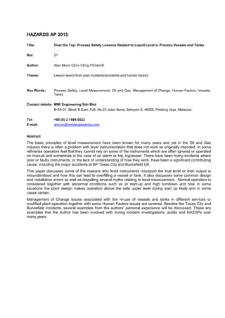
Figure 1 – Texas City Raffinate Splitter: Simplified bottoms arrangement showing effect of density
difference
Instruments also have to be calibrated for the correct temperature. During the initial fill, the SG was higher
(cold); as the tower heated up the SG decreased (hotter) and the operators saw the level coming down, even
though it was actually above 100%. This is exactly as one would expect based on the operation of a DP cell.
This is an example of lack of understanding of how level instruments work; specifically DP cells that measure
differential pressure between two points and how these are affected by changes in fluid density or SG. This
would have been compounded by confirmation bias or seeing what one is expecting to see. The Operator
expected to see the level coming down and this was what appeared to be happening albeit very slowly.
Page 5 of 11
6. Over the Top: Process Safety Lessons Related to Liquid Level in Process Vessels and Tanks
Case Study 3 - HF Alkylation Unit: Main Fractionator Bottoms Level
Alkylate is a gasoline blend stock. The column bottoms operates at about 215
o
C and the nozzles used to
regularly plug up with iron fluoride deposits leading to a false high level. The Controller (or the Operator)
would increase the bottoms flow leading to a loss of level in the tower, the LSL alarm and trip failed to operate
and the bottoms pumps would cavitate, leading to a trip of the fired reboiler and possible pump seal damage
or failure and potential loss of containment. This is an old case study, nowadays the low level switch which
tripped the bottoms pump would probably be classed as safety critical and be designed with an independent
level signal, routinely tested and SIL rated etc.
The solution was to install an extra set of nozzles on the tower (expensive) with a separate level indicator and
an independent controller and trips. The intent was also to trend both instruments against each other so that
when one failed it would quickly be seen and could be cleared. The controller could be configured for either
level instrument. In addition daily flushing and rodding was required as a continuous purge was not possible.
Nowadays an automatic rodding system could be installed to keep the nozzles clear (with monel lined nozzles
and taking care not to remove all the iron fluoride protective layer).
Figure 2 – HF Alkylation Unit: Main Fractionator Bottoms
These modifications had disappointing results, as what happened was that over several months, the routine
flushing and rodding became less frequent as it was not seen as necessary since there was a spare
instrument so they waited until one plugged up before clearing it. Eventually, even when one set was plugged,
it was not seen as a priority to fix it as the second set worked, so it would take days or even weeks to get
fixed. The end result was that loss of level still regularly occurred! This is another example of ‘Normalisation of
Deviance’, the routine acceptance of a high risk.
Page 6 of 11
7. Over the Top: Process Safety Lessons Related to Liquid Level in Process Vessels and Tanks
Case Study 4 - HF Alkylation Unit: Depropanizer Bottoms Level
The depropanizer bottoms level instrument was unreliable occasionally causing problems with the tower
operation and pressure upsets. Generally these were not safety concerns but caused operational problems
and loss of isobutane. It was also possible to discharge liquid via the PSV located below the bottom tray.
The depropanizer column is fitted with a stab-in steam reboiler and as a result the bottoms section contained
boiling isobutane and was very turbulent. The problem here is what do we mean by the level of a boiling
liquid? Imagine trying to measure the level in a boiling kettle with all the steam bubbles being formed. We
were trying to measure something that doesn’t actually exist.
Measuring the ‘level’ was necessary to control the bottoms flow and prevent liquid at the PSV inlet, flooding in
the column or vapour break-through downstream. The PSV was at the bottom of the tower because of HF in
the overheads. The solution to this situation was to add an internal baffle and measure an ‘inferred level’ or
even not to measure the ‘level’ at all, but to measure the DP between the pump suction and below the bottom
tray although there was much resistance to this second proposal.
This is an example of how the designers, engineers and the operators failed to understand what was actually
occurring inside the column. There was also significant resistance to the concept of not measuring the ‘level‘at
all since the belief that there was a defined level in the column remained.
As an aside – this is why measuring the ‘level’ in boilers is often difficult or impossible.
Figure 3 – Depropanizer bottoms arrangement
Page 7 of 11
8. Over the Top: Process Safety Lessons Related to Liquid Level in Process Vessels and Tanks
Case Study 5 - Low Level trip on Pump Suction Line
A SIL rated low level trip had been installed to prevent damage to the pump seal and potential seal failure and
loss of containment. This was not part of the original design for the plant but a modification. The plant had
also been debottlenecked so that the capacity was significantly higher than the original design. The drum
diameter was about 1.2m and contained sour diesel like material at about 30–40
o
C.
The pump would trip at high rates even though there was a liquid level in the drum as could be seen in the
sight glass and on the level controller. As the plant was always running at high rates, the pump kept tripping
and so the operators had disabled it. Therefore, if there was a true low level the system was unprotected.
Figure 4 – Low Level trip on pump suction line
In this case the problem was due to the location of the level take offs, the bottom take off being in the suction
line near to the pump. As there were no available nozzles on the drum when the trip was installed, the Project
Engineer had used an available connection on the suction line. The suction line was undersized and the
resulting pressure drop in the line was significant even though the pump NPSH requirements were satisfied.
The level switch was a float type and because of the pressure drop in the line, the level in the float chamber
was lower than in the drum especially at higher rates, thus causing the float switch to activate.
Page 8 of 11
9. Over the Top: Process Safety Lessons Related to Liquid Level in Process Vessels and Tanks
Case Study 6 - Guided Wave Radar on Batch Reactor
A batch reactor system was fitted with a float type level indicator in an internal slotted stilling pole. Some of
the chemicals used in the reaction were quite viscous and so the float used to get stuck occasionally.
The operating sequence was as follows; the reactor was initially filled with chemical A and then topped up with
several other chemicals (B, C etc.), all with different densities. The reaction takes place resulting in volume
and temperature changes. Clearly any instrument dependant on the density of the liquid would not work.
The vendor suggested installing a Guided Wave Radar (GWR) and this was accepted by the Process
Engineer as a GWR is a direct measurement technique rather than an inferred type.
A HAZOP was performed on the modification during which it was discovered that the GWR was to be installed
in a ‘bypass line’ rather than in the original stilling pole as expected. As a result the instrument would still have
been inaccurate due to density variations as discussed previously.
This is a common arrangement for GWRs; all the vendors supply this as an option. There are some benefits,
but it is not direct measurement of the liquid level in the vessel.
In this case the problem was due to lack of communication between the Process Engineer, the Project
Engineer and the Vendor. The Process Engineer assumed that the GWR would be installed in the existing
stilling well and left it to the Project Engineer and Vendor to get on with the job. The Vendor was aware of the
problem with the stilling well plugging up so decided to supply the bypass line option to enable it to be
cleaned.
Figure 5 – Guided Wave Radar on Batch Reactor
Page 9 of 11
10. Over the Top: Process Safety Lessons Related to Liquid Level in Process Vessels and Tanks
Case Study 7 - HF Alkylation Unit Emergency Acid Dump Drum
The final case study involves foaming and multiple phases, both of which are responsible for numerous level
measurement problems.
This was on a Re-HAZOP of a retrofit project that had been in operation for many years. The emergency
dump system is designed to empty the unit of HF in a major fire or loss of containment event thus minimising
the amount of HF released. The drum was sized to take the full inventory of the HF reactor system including
alkylate (gasoline) and unreacted butane, about 40 Tonnes in total. Transfer time was about 8-10 minutes and
any vapours would be discharged via a caustic scrubber to the flare. There were 2 problems with the system;
foaming and there was no way to measure the hydrocarbon phase in the drum.
Foaming is a common problem in the Oil and Gas industry. Foam has a variable density, less than the liquid
that is being measured. So the indicated level was lower than the height of the foam which could result in
foam being routed to the Caustic Scrubber. As the foam contained lots of HF this could cause a violent
reaction in the scrubber and/or spend the caustic allowing HF breakthrough to the flare system.
The level instrument only had 2 take-offs from the vessel, so the bottom connection always filled with HF and
because of the different densities, the indicated level was always lower than the actual level in the drum.
There was no way of measuring each layer separately; to do so, requires multiple connections to the vessel.
The operators had been complaining for years that they had no way of measuring the hydrocarbon content in
the drum, which made it very difficult to transfer material back to the unit in a controlled manner. The problem
was that the material separated into 3 layers:
• Foam
• Hydrocarbon
• HF
The ideal solution was to install an internal GDR system that was able to detect the interfaces, however cost
considerations led to multiple take offs with magnetic float indicators being installed.
Figure 6 – Multiple layers in Alkylation Unit Emergency Acid Dump Drum
Page 10 of 11
11. Over the Top: Process Safety Lessons Related to Liquid Level in Process Vessels and Tanks
HAZOPs and Process Hazards Analysis (PHA)
In a HAZOP or PHA we identify “causes” of hazardous events; these are either equipment failures or human
failures. Level problems can be both.
Although there is not time in a HAZOP for a detailed analysis of any instruments, it is important to ensure that
the level instruments we are relying on for control or as safeguards actually work. Listen to the Operators who
will be aware of any problems, get the Process Engineer to check instrument logs and sometimes a physical
check on the plant may be necessary. Often the P&IDs incorrectly shows the instrument piping details.
Another common omission in HAZOP/PHAs is to not consider all possible causes for process vessel “level”
deviations. The workshop team will often assume all possible causes of high, low or no/zero level are covered
by the previous HAZOP/PHA guideword discussions, e.g. flow, pressure and temperature deviations.
However, as described in the case studies in this paper, there are many other causes of level deviations
including foaming, calibration error, instrument technology, change in composition of feed fluid, interface
levels, direct or indirect measurement etc. The process engineer should highlight relevant level issues during
the HAZOP/PHA.
Finally, don’t expect the Instrument Engineer, Vendor or Process Design Engineer to understand how a level
instrument works in your situation. Often no one in the HAZOP team does! This should be the Process
Engineer’s role.
SIL Assessments
Just because an instrument has independent signals/tappings and is backed up by alternative/diverse level
technologies, to prevent common cause failure; and is SIL rated/certified and regularly tested etc., does not
necessarily mean that the complete loop (wet-end to wet-end) meets the SIL requirement. The level in the
instrument or standpipe may well be different to the level in the vessel and this can lead to significant errors
which in some cases can defeat the alarm or trip systems. In addition, nozzles can and often do plug up,
leading to a false level indication which can go unnoticed for long periods potentially leading to failure of the
alarm or trip system.
Conclusions
Failure of level instruments and incorrect level measurement has caused many accidents, some of them large
leading to fatalities, environmental damage and significant financial loss to owner companies and the public.
The key to avoiding level related incidents is to understand how the instruments work in the particular
situation; don’t assume that “someone else” will do this, which is often not the case.
Don’t assume the design is correct; sometimes there are errors, especially when the project is on a fast track
schedule. This is why it is so important for any design to go through a thorough design review and having client
process engineers and operators on the design review and HAZOP teams to properly challenge the basis of design and
safeguarding philosophy.
Adopt a questioning or challenging mind-set. Operators should be taught to question instruments readings
and look for independent verification, especially during upset conditions. A good Process and Process Safety
Engineer (including HAZOP/PHA facilitators) must understand the measurement system and technology so
they can understand and correctly interpret the reported results.
The case studies in this paper are presented in the hope that some of the lessons learnt will be incorporated
into future designs and operating practices and thus reduce the risk of future incidents.
Page 11 of 11