
Recommandé
Contenu connexe
Tendances
Tendances (20)
En vedette
En vedette (20)
Similaire à Elements analysis dfd_er_std
Similaire à Elements analysis dfd_er_std (20)
Dernier
Dernier (20)
Elements analysis dfd_er_std
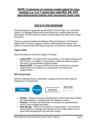
- 1. PREPARED BY: NIDHI SOLANKI (ASSIST. PROF., MKICS) Page 1 NOTE: If elements of analysis model asked for long question i.e. 5 or 7 marks then add DFD, ER, STD description(given below),with previously given note DATA FLOW DIAGRAM Data flow diagram is graphical representation of flow of data in an information system. It is capable of depicting incoming data flow, outgoing data flow and stored data. The DFD does not mention anything about how data flows through the system. There is a prominent difference between DFD and Flowchart. The flowchart depicts flow of control in program modules. DFDs depict flow of data in the system at various levels. DFD does not contain any control or branch elements. Types of DFD Data Flow Diagrams are either Logical or Physical. • Logical DFD - This type of DFD concentrates on the system process and flow of data in the system. For example in a Banking software system, how data is moved between different entities. • Physical DFD - This type of DFD shows how the data flow is actually implemented in the system. It is more specific and close to the implementation. DFD Components DFD can represent Source, destination, storage and flow of data using the following set of components - • Entities - Entities are source and destination of information data. Entities are represented by a rectangle with their respective names. • Process - Activities and action taken on the data are represented by Circle or Round-edged rectangles. • Data Storage - There are two variants of data storage - it can either be represented as a rectangle with absence of both smaller sides or as an open-sided rectangle with only one side missing.
- 2. PREPARED BY: NIDHI SOLANKI (ASSIST. PROF., MKICS) Page 2 • Data Flow - Movement of data is shown by pointed arrows. Data movement is shown from the base of arrow as its source towards head of the arrow as destination. Levels of DFD • Level 0 - Highest abstraction level DFD is known as Level 0 DFD, which depicts the entire information system as one diagram concealing all the underlying details. Level 0 DFDs are also known as context level DFDs. • Level 1 - The Level 0 DFD is broken down into more specific, Level 1 DFD. Level 1 DFD depicts basic modules in the system and flow of data among various modules. Level 1 DFD also mentions basic processes and sources of information.
- 3. PREPARED BY: NIDHI SOLANKI (ASSIST. PROF., MKICS) Page 3 • • Level 2 - At this level, DFD shows how data flows inside the modules mentioned in Level 1. Higher level DFDs can be transformed into more specific lower level DFDs with deeper level of understanding unless the desired level of specification is achieved. ENTITY-RELATIONSHIP MODEL Entity-Relationship model is a type of database model based on the notion of real world entities and relationship among them. We can map real world scenario onto ER database model. ER Model creates a set of entities with their attributes, a set of constraints and relation among them. ER Model is best used for the conceptual design of database. ER Model can be represented as follows:
- 4. PREPARED BY: NIDHI SOLANKI (ASSIST. PROF., MKICS) Page 4 • Entity - An entity in ER Model is a real world being, which has some properties called attributes. Every attribute is defined by its corresponding set of values, called domain. For example, consider a school database. Here, a student is an entity. Student has various attributes like name, id, age and class etc. • Relationship - The logical association among entities is called relationship. Relationships are mapped with entities in various ways. Mapping cardinalities define the number of associations between two entities. Mapping cardinalities: o one to one o one to many o many to one o many to many
- 5. PREPARED BY: NIDHI SOLANKI (ASSIST. PROF., MKICS) Page 5 STATE TRANSITION DIAGRAM: A state diagram is a type of diagram used in computer science and related fields to describe the behavior of systems. State diagrams require that the system described is composed of a finite number of states. Many forms of state diagrams exist, which differ slightly and have different semantics.