SlideShare une entreprise Scribd logo
1  sur  11
Télécharger pour lire hors ligne
CHAPTER 3
DATA COMMUNICATION
DATA
The collection of raw facts and figures is called data. The word data is derived from
the Latin language and it is the plural of Datum. The text, numbers, symbols, images,
voice, and video which are processed by computers and digital devices are called data.
Data can be considered unprocessed information.
COMMUNICATION
Communication is the process of sharing a message. A conversation between two
people is an example of communication.
DATA COMMUNICATION
Data Communication is the process of transferring data electrically from one place to
another. It is the process of exchange of data and information between two parties
such as humans and electronic or computing devices.
COMPONENTS OF THE COMMUNICATION SYSTEM
A Communication system has the following five components.
 Message
It is the information or data to be communicated. Common forms of information
include text, numbers, pictures, audio, and video.
 Sender
It is the device that generates and sends a message. It can be a computer,
telephone handset, etc.
 Receiver
Any particular digital electronic device can receive data in form of a message.
The location of receiving computer is generally different from the sending
computer. Like the sender, it can also be a computer, telephone handset, etc.
 Medium
It is the channel or path through which the message is carried from the sender to
the receiver. Some examples include twisted-pair cable, coaxial cable, radio
waves, etc.
 Protocol
Protocols are the rules and procedures by which computers exchange data on the
network. The sender and receiver follow the same protocols to communicate with
each other. In other words, a protocol is an agreement between two parties or
vendors, using communication devices.
STANDARDS
Standards are the set of rules for data communication that are needed for the exchange
of information among devices. It is important to follow Standards that are created by
various Standard Organizations like IEEE, ISO, ANSI, etc.
OR
Standards are rules that define the appearance, functionality, or protocols of some
equipment. They are essential for network communication. Network standards define
rules of communication among computing devices. This ensures that companies (i.e.
Cisco and IBM) that manufacture computing and networking products follow these
uniform standards. By following standards, all hardware becomes compatible with the
network, allowing efficient networking to take place.
CHARACTERISTICS OF DATA TRANSMISSIONS
Data communication has several characteristics but some are discussed below:
1. Signal type
2. Transmission mode
3. Direction of transmission
1. SIGNAL
A signal is an electromagnetic or electrical current that carries data from one system
or network to another.
TYPES OF SIGNAL
There are two types of signals discussed below:
 Analog Signals
Analog signals are continuously varying signals or waves that change with time
and are used to represent data. An analog signal can be used to measure
changes in some physical quantities such as light, sound, pressure, or
temperature.
Example
An example of an analog signal is the human voice. When we speak, we use air
to transmit an analog signal. An electrical signal from an audio tape can also be
in analog form.
 Characteristics Of Analog Signals
 Amplitude
The amplitude of a signal refers to the height of the signal. It is equal to
the vertical distance from a given point on the waveform to the
horizontal axis. It is measured in volts.
 Frequency
Frequency refers to the number of periods in one second or the number
of cycles per second. Frequency is measured in Hertz (Hz).
 Digital Signals
A digital signal is an electrical signal that is converted into a pattern of bits to
represent a sequence of discrete values, at any given time. It can only be one of
the finite numbers represented as 0 or 1.
Examples
Examples of digital signals are Computers, Digital Phones, Digital pens, etc.
DIFFERENCE BETWEEN ANALOG AND DIGITAL SIGNAL
PARAMETERS ANALOG SIGNAL DIGITAL SIGNAL
Definition
An analog signal is a
continuous wave that
changes over time.
A digital signal is a discrete
wave that carries information
in binary form.
Range
The Analog signal has no
fixed range.
Digital signal has an infinite
number i.e. 0 and 1.
Flexibility
Analog hardware is not
flexible.
Digital hardware is flexible in
implementation.
Representation
An analog signal is
represented by a sine wave.
A digital signal is represented
by square waves
Examples
The human voice is an
example of an analog signal.
Signals used by the computer
are the digital signal.
2. TRANSMISSION MODES (Asynchronous And Synchronous)
Transmission is the action of transferring or moving something from one position or
person to another. It is a mechanism for transferring data between two devices
connected using a network. It is also called communication Mode. In computer
networking there are two types of transmission:
 Synchronous transmissions
 Asynchronous transmissions
 ASYNCHRONOUS TRANSMISSION
In Asynchronous Transmission, data is sent in form of a byte or character. This
transmission is the half-duplex type transmission. In this transmission start bits and
stop bits are added to the data. It does not require synchronization.
EXAMPLE
 Email
 Forums
 Letters etc.
 SYNCHRONOUS TRANSMISSION
In Synchronous Transmission, data is sent in form of blocks or frames. This
transmission is the full-duplex type. Between sender and receiver, synchronization is
compulsory. In Synchronous transmission, There is no gap present between data. It is
efficient and more reliable than asynchronous transmission to transfer a large amount
of data.
EXAMPLE
 Chat Rooms
 Telephonic Conversations
 Video Conferencing etc.
DIFFERENCES BETWEEN SYNCHRONOUS AND ASYNCHRONOUS
TRANSMISSION
SYNCHRONOUS
TRANSMISSION
ASYNCHRONOUS
TRANSMISSION
In Synchronous transmission, data is
sent in form of blocks or frames.
In Asynchronous transmission, data is
sent in form of bytes or characters.
Synchronous transmission is fast. Asynchronous transmission is slow.
Synchronous transmission is costly Synchronous transmission is costly
In Synchronous transmission, the time
interval of transmission is constant.
In Asynchronous transmission, the time
interval of transmission is not constant,
it is random.
In this transmission, users have to
wait till the transmission is complete
before getting a response back from
Here, users do not have to wait for the
completion of transmission to get a
response from the server.
the server.
In Synchronous transmission, there is
no gap present between data.
In Asynchronous transmission, there is
a gap present between data.
Efficient use of transmission lines is
done in synchronous transmission.
While in Asynchronous transmission,
the transmission line remains empty
during a gap in character transmission.
The start and stop bits are not used in
transmitting data.
The start and stop bits are used in
transmitting data that imposes extra
overhead.
Synchronous transmission needs
precisely synchronized clocks for the
information of new bytes.
Asynchronous transmission does not
need synchronized clocks as a parity
bit is used in this transmission for
information of new bytes.
3. DIRECTION OF TRANSMISSION
Another characteristic of data transmission is direction Data may flow in more than
one direction. There are three types of transmission modes. They are:
 Simplex Mode
 Half-duplex Mode
 Full-duplex Mode
 Simplex Mode
Simplex is the data transmission mode in which the data can flow only in one
direction, i.e., the communication is unidirectional. In this mode, a sender can
only send data but can not receive it, and vice versa.
OR
In simplex mode, Sender can send the data but the sender can’t receive the data.
It is unidirectional communication.
Example
Radio and TV transmission, keyboard, mouse, etc.
Advantages
 It utilizes the full capacity of the communication channel during data
transmission.
 It has the least or no data traffic issues as data flows only in one direction.
Disadvantages
 It is unidirectional having no inter-communication between devices.
 There is no mechanism for information to be transmitted back to the
sender(No mechanism for acknowledgment).
 Half-Duplex Mode
In half-duplex mode, each station can both transmit and receive, but not at
the same time. When one device is sending, the other can only receive it, and
vice versa. The half-duplex mode is used in cases where there is no need for
communication in both directions at the same time.
OR
In half-duplex mode, Sender can send the data and also can receive the data
one at a time. It is two-way directional communication but one at a time.
Example
Walkie-talkie in which message is sent one at a time and messages are sent in
both directions.
Advantages
 Speed is a big advantage of a full-duplex.
 The device can receive and send data, but not at the same time.
 Troubleshooting is very easy
 Data is transmitted on both sides
Disadvantages
 In a half Duplex, more data cannot be transmitted on both sides at the same
time.
 When one device sends data, the device on the other hand only receives data.
 It is slow in data transmission.
 Delay in data transmission.
 Full-Duplex Mode
In full-duplex mode, both stations can transmit and receive simultaneously.
In full-duplex mode, signals going in one direction share the capacity of the
link with signals going in another direction, this sharing can occur in two
ways:
 Either the link must contain two physically separate transmission paths,
one for sending and the other for receiving.
 Or the capacity is divided between signals traveling in both directions.
OR
In full-duplex mode, Sender can send the data and also can receive the data
simultaneously. It is two-way directional communication simultaneously.
Example:
Telephone Network in which there is communication between two persons by a
telephone line, through which both can talk and listen at the same time.
Advantages
 Performance of full-duplex mode is much better than half and simplex mode.
 The speed of full-duplex mode is high than simplex and half-duplex mode.
 Data can be sent and received on both sides, which increases the
performance of the network.
 No delay in communication, because both devices send and receive data at
the same time.
Disadvantages
 No proper bandwidth utilization as the same line is used for sending and
receiving data at the same time.
 It is more complex than a simplex and half-duplex mode.
DIFFERENCES BETWEEN THE TYPES OF TRANSMISSION MODES
PARAMETERS
SIMPLEX
MODE
HALF DUPLEX
MODE
FULL-DUPLEX
MODE
Direction Of Simplex mode is a Half Duplex mode Full-Duplex mode
Communication uni-directional
communication.
is a two-way
directional
communication but
one at a time.
is a two-way
directional
communication
simultaneously.
Sender And
Receiver
In simplex mode,
Sender can send
the data but the
sender can’t
receive the data.
In Half-duplex
mode, Sender can
send the data and
also can receive
the data one at a
time.
In Full-duplex
mode, Sender can
send the data and
also can receive
the data
simultaneously.
Channel Usage
Usage of one
channel for the
transmission of
data.
Usage of one
channel for the
transmission of
data.
Usage of two
channels for the
transmission of
data.
Performance
The simplex mode
provides less
performance than a
half duplex and a
full duplex.
The Half-duplex
mode provides less
performance than
the full duplex.
Full-duplex
provides better
performance than
simplex and half-
duplex modes.
Bandwidth
Utilization
Simplex utilizes
the maximum of a
single bandwidth.
The Half-duplex
involves lesser
utilization of single
bandwidth at the
time of
transmission.
The Full-duplex
doubles the
utilization of
transmission
bandwidth.
Examples
Keyboard and
monitor Walkie-
talkie
The walkie-talkie
is an example of a
half-duplex mode.
The telephone
network is an
example of a full-
duplex mode.
DATA COMMUNICATION SPEED AND MEDIA
BANDWIDTH
Bandwidth is the maximum rate at which data transfer occurs across any particular
path of the network. OR
The data handling capacity of a media is referred to as its bandwidth. Bandwidth is
the range of frequencies that is available for the transmission of data. There are
some types of bandwidth are discussed below:
 Narrowband
The media communicate data at a relatively slow speed. Examples are
telegraph lines.
 Voice band
These media are faster than narrowband. Most telephone lines that are used
to carry microcomputer transmissions are voice bands.
 Broadband
These media transmit large volumes of data at high speed via microwave,
satellite, coaxial cable, and fiber optics cable. It is also called a wind band.
COMMUNICATION MEDIAS
Communication media refers to the medium through which data transmission from
the transmitter to the receiver takes place. The most common media for data
communications are twisted-pair cable, coaxial cable, fiber optics cable, microwave,
and satellite.
 Twisted-Pair Cable
Twisted pair cables were one of the earliest directed transmission media. A
twisted pair cable is made up of two individual, insulated copper wires that
are twisted together and run parallel. Usually 1mm in diameter, copper wires.
Data is transmitted through one wire while ground reference is provided by
the other.
Reason for twisting
All transmissions frequently experience noise, interference, and crosstalk.
When the wires are twisted, some of the noise signals move together with the
data signals while the other parts move in the other direction. The outside
waves are canceled out by the unique twists. By computing the voltage
difference between the two wires, the receiver can recover data. As a result,
noise immunity is significantly improved.
 Coaxial Cable
An electrical cable containing a copper conductor, an insulator covering it,
and a braided metal mesh that reduces crosstalk and signal interference is
known as a coaxial cable. Coax is another name for coaxial cable.
Coaxial cable offers much higher bandwidths and supports transmission
speeds up to 10 megabits per second (Mbps). It can carry more data than
older types of twisted pair cable. However, it is also expensive.
 Fiber Optics Cable
A fiber optic cable is made of glass or plastic and transmits signals in the
structure of light signals. It involves an inner glass core surrounded by a
glass cladding that reflects the light into the core. Each fiber is encircled by
a plastic jacket.
Semiconductor lasers transmit data in the form of light along with hair-thin
glass fiber optic cables at the speed of light with no significant loss of
intensity over very long distances. The system includes fiber optic cables
that are made of tiny threads of glass or plastic.
Advantages of Fiber Optic Cables
The advantage of fiber optics cable are listed below:
 Small Size and Lightweight
The size of the optical fiber optic cables is minimal.
 Easily available and low cost
Silica glass is the substance used to make fiber optic cables. As a result,
fiber optic cables are less expensive than cables with metallic conductors.
 No electrical or electromagnetic interface
The signal is unaffected by electrical or electromagnetic interference
since the transmission uses light rays.
 Large Bandwidth
The fiber optic cable bandwidth is exceptionally wide since the light
arrays operate at very high frequencies in the GHz range. This makes it
possible to transmit more channels. As a result, a fiber optic cable has a
substantially larger information-carrying capacity than a coaxial wire.
Disadvantages of Fiber Optic Cables
The disadvantage of fiber optics cable are listed below:
 High Cost
In comparison to other guided media, the cost of the cable and interfaces
is higher.
 Unidirectional light propagation
Two-way communication requires either two fiber optic cables or two
frequency bands on a single fiber because optical transmission is by
nature unidirectional.
 Installation and Maintenance
fiber is different technology requiring skills; most engineers do not
occupy. It is defined as fixed point-to-point ground installations.
 Microwaves
Microwave transmission is a line-of-sight transmission i.e. the sending and
receiving antennas need to be properly aligned with each other. The distance
covered by the signal is directly proportional to the height of the antenna.
These are mostly used for mobile phone communications towers and
television broadcasts. Terrestrial and Satellite are two types of microwave
transmissions.
 Terrestrial
Terrestrial microwaves have both stations having antennas on earth.
 Satellite
In a satellite system, some antennas are on satellites in orbit and others
are on stations on earth. They work at remote places so they can be used
on mobile devices.
COMMUNICATION HARDWARE
MODEM
A modem is short for Modulator and Demodulator. Modulation is the process of
converting digital signals into analog signals. Demodulation is quite opposite; it
converts analog signals into digital signals. The modem can send and receive signals
that allow computers to share information. This sharing of information is possible
over phone lines, cables, or satellite connections.
Modulation
Demodulation
OSI MODEL
The Open Systems Interconnection model is a
conceptual model developed by ISO. It characterizes
and standardizes the communication functions of a
telecommunication and computing network. Its goal is
the interoperability of different communication
systems with standard communication protocols. This
model divides a communication system into seven abstraction layers.
 Application Layer
This layer enables users to access the network with applications such as
email, file transfer, etc. These applications produce the data, which is
transferred over the network.
 Presentation Layer
It receives information from the application layer and converts it to a uniform
network format (ASCII or Unicode) which is acceptable by the rest of the
OSI model and destination. Encryption and decryption are also the
responsibility of this layer. This layer also reduces the number of transfer bits
by compression.
 Session Layer
This layer establishes, maintains, and ends a session or logical connection
between applications on two computers. It manages who can transmit data at
a certain time and for how long. This layer adds checkpoints. If the session
fails only data after the most recent checkpoint need to be transmitted.
 Transport Layer
It ensures the reliable transmission of data. The transport layer manages error
control, ow control, and quality of the service. If the data is not properly
transmitted it requests to be resent.
 Network Layer
The function of this layer is the selection of the shortest and most suitable
path from source to destination, from the number of routes available. It is
also responsible to convert logical addresses (IP addresses) to physical
addresses (MAC addresses).
 Data Link Layer
This layer is responsible to transmit data using physical addresses. The data
link layer ensures error free transmission of packets. The packet in this layer
is referred to as the frame.
 Physical Layer
It is responsible for converting electrical signals into bits. It also defines the
cable types to be used as transmission media, cards, topology, and other
physical aspects.

Contenu connexe

Tendances

TCP/IP Network ppt
TCP/IP Network pptTCP/IP Network ppt
TCP/IP Network ppt
extraganesh
 
Analog and Digital Signals
Analog and Digital SignalsAnalog and Digital Signals
Analog and Digital Signals
Sana Ullah
 

Tendances (20)

Introduction to Data Communication
Introduction to Data CommunicationIntroduction to Data Communication
Introduction to Data Communication
 
TCP/IP Network ppt
TCP/IP Network pptTCP/IP Network ppt
TCP/IP Network ppt
 
Analog and Digital Signals
Analog and Digital SignalsAnalog and Digital Signals
Analog and Digital Signals
 
OSI Model
OSI ModelOSI Model
OSI Model
 
Data communication
Data communicationData communication
Data communication
 
Multiplexing
MultiplexingMultiplexing
Multiplexing
 
Transmission Modes in Computer Networks
Transmission Modes in Computer Networks Transmission Modes in Computer Networks
Transmission Modes in Computer Networks
 
Presentation on DSL & ADSL
Presentation on DSL & ADSLPresentation on DSL & ADSL
Presentation on DSL & ADSL
 
Computer network
Computer networkComputer network
Computer network
 
Powerpoint for data communication
Powerpoint for data communication Powerpoint for data communication
Powerpoint for data communication
 
Data communication (simple explanation)
Data communication (simple explanation)Data communication (simple explanation)
Data communication (simple explanation)
 
Chapter 1 Fundamentals of Database Management System
Chapter 1 Fundamentals of Database Management SystemChapter 1 Fundamentals of Database Management System
Chapter 1 Fundamentals of Database Management System
 
External memory
External memoryExternal memory
External memory
 
Multiple Access Protocal
Multiple Access ProtocalMultiple Access Protocal
Multiple Access Protocal
 
Unit 1 introduction to computer networks
Unit 1  introduction to computer networksUnit 1  introduction to computer networks
Unit 1 introduction to computer networks
 
Dbms schema & instance
Dbms schema & instanceDbms schema & instance
Dbms schema & instance
 
TCP IP Model | Computer Science
TCP IP Model | Computer ScienceTCP IP Model | Computer Science
TCP IP Model | Computer Science
 
Fundamentals of Database system
Fundamentals of Database systemFundamentals of Database system
Fundamentals of Database system
 
DATABASE MANAGEMENT SYSTEM
DATABASE MANAGEMENT SYSTEMDATABASE MANAGEMENT SYSTEM
DATABASE MANAGEMENT SYSTEM
 
02 xml schema
02 xml schema02 xml schema
02 xml schema
 

Similaire à Complete CHAPTER 3 Data Communication.pdf

Learning Guide of Determine Best Fit Topology LO 2.pptx
Learning Guide of Determine Best Fit Topology LO 2.pptxLearning Guide of Determine Best Fit Topology LO 2.pptx
Learning Guide of Determine Best Fit Topology LO 2.pptx
aytenewbelay1
 
Ch2 Data communication.pptx
Ch2 Data communication.pptxCh2 Data communication.pptx
Ch2 Data communication.pptx
kebeAman
 
Lesson 5 data communication and networking (136 kb)
Lesson 5   data communication and networking (136 kb)Lesson 5   data communication and networking (136 kb)
Lesson 5 data communication and networking (136 kb)
IMRAN KHAN
 
Lesson 4 communication and computer network (123 kb)
Lesson 4 communication and computer network (123 kb)Lesson 4 communication and computer network (123 kb)
Lesson 4 communication and computer network (123 kb)
IMRAN KHAN
 

Similaire à Complete CHAPTER 3 Data Communication.pdf (20)

CND_22634_UNIT1_MSBTE_Computer network and Data Communication
CND_22634_UNIT1_MSBTE_Computer network and Data CommunicationCND_22634_UNIT1_MSBTE_Computer network and Data Communication
CND_22634_UNIT1_MSBTE_Computer network and Data Communication
 
Computer networks and internet www.it-workss.com
Computer networks and internet   www.it-workss.comComputer networks and internet   www.it-workss.com
Computer networks and internet www.it-workss.com
 
Data Communication & Networks
Data Communication & NetworksData Communication & Networks
Data Communication & Networks
 
Introduction to Data Communication by Vishal Garg
Introduction to Data Communication by Vishal GargIntroduction to Data Communication by Vishal Garg
Introduction to Data Communication by Vishal Garg
 
Ch 01 part 1 - basic elements of telecommunication systems
Ch 01   part 1 - basic elements of telecommunication systemsCh 01   part 1 - basic elements of telecommunication systems
Ch 01 part 1 - basic elements of telecommunication systems
 
dc1.pdf
dc1.pdfdc1.pdf
dc1.pdf
 
Learning Guide of Determine Best Fit Topology LO 2.pptx
Learning Guide of Determine Best Fit Topology LO 2.pptxLearning Guide of Determine Best Fit Topology LO 2.pptx
Learning Guide of Determine Best Fit Topology LO 2.pptx
 
Ch#3.pptx
Ch#3.pptxCh#3.pptx
Ch#3.pptx
 
Computer Networks for Computer Science Student
Computer Networks for Computer Science StudentComputer Networks for Computer Science Student
Computer Networks for Computer Science Student
 
1834902182 julkar naim_dcam
1834902182 julkar naim_dcam1834902182 julkar naim_dcam
1834902182 julkar naim_dcam
 
2.pptx
2.pptx2.pptx
2.pptx
 
Week 3 indiv to post ok
Week 3 indiv to post okWeek 3 indiv to post ok
Week 3 indiv to post ok
 
Week 3 indiv to post ok
Week 3 indiv to post okWeek 3 indiv to post ok
Week 3 indiv to post ok
 
Ch2 Data communication.pptx
Ch2 Data communication.pptxCh2 Data communication.pptx
Ch2 Data communication.pptx
 
Lecture 1 data communication
Lecture 1 data communicationLecture 1 data communication
Lecture 1 data communication
 
Chapter 1 introduction haramaya
Chapter 1 introduction haramayaChapter 1 introduction haramaya
Chapter 1 introduction haramaya
 
Lesson 5 data communication and networking (136 kb)
Lesson 5   data communication and networking (136 kb)Lesson 5   data communication and networking (136 kb)
Lesson 5 data communication and networking (136 kb)
 
Wolkite polytechnic college ICT Department
Wolkite polytechnic college ICT Department Wolkite polytechnic college ICT Department
Wolkite polytechnic college ICT Department
 
Lesson 4 communication and computer network (123 kb)
Lesson 4 communication and computer network (123 kb)Lesson 4 communication and computer network (123 kb)
Lesson 4 communication and computer network (123 kb)
 
Dc assignment
Dc assignmentDc assignment
Dc assignment
 

Plus de Amna Nawazish

CHAPTER 3 Data Communication.pdf
CHAPTER 3 Data Communication.pdfCHAPTER 3 Data Communication.pdf
CHAPTER 3 Data Communication.pdf
Amna Nawazish
 

Plus de Amna Nawazish (16)

CHAPTER 3 Data Communication.pdf
CHAPTER 3 Data Communication.pdfCHAPTER 3 Data Communication.pdf
CHAPTER 3 Data Communication.pdf
 
MOTION & MANIPULIATION IN ARTIFICIAL INTELLIGENCE.pdf
MOTION & MANIPULIATION IN ARTIFICIAL INTELLIGENCE.pdfMOTION & MANIPULIATION IN ARTIFICIAL INTELLIGENCE.pdf
MOTION & MANIPULIATION IN ARTIFICIAL INTELLIGENCE.pdf
 
ELEMENT COMPOUND & MIXTURES ELEMENT
ELEMENT COMPOUND & MIXTURES ELEMENTELEMENT COMPOUND & MIXTURES ELEMENT
ELEMENT COMPOUND & MIXTURES ELEMENT
 
Short note Lahore Resolution or Pakistan Resolution 1940, Delhi Proposal 1929...
Short note Lahore Resolution or Pakistan Resolution 1940, Delhi Proposal 1929...Short note Lahore Resolution or Pakistan Resolution 1940, Delhi Proposal 1929...
Short note Lahore Resolution or Pakistan Resolution 1940, Delhi Proposal 1929...
 
Life of Ali Ibn Talib
Life of Ali Ibn TalibLife of Ali Ibn Talib
Life of Ali Ibn Talib
 
Routing
RoutingRouting
Routing
 
Routing Information Protocol (RIP)
Routing Information Protocol (RIP)Routing Information Protocol (RIP)
Routing Information Protocol (RIP)
 
Routing Information Protocol(RIP)
Routing Information Protocol(RIP)Routing Information Protocol(RIP)
Routing Information Protocol(RIP)
 
External memory
External memoryExternal memory
External memory
 
Pros & Cons of globalization
Pros & Cons of globalizationPros & Cons of globalization
Pros & Cons of globalization
 
Online doctor appointment
Online doctor appointmentOnline doctor appointment
Online doctor appointment
 
Calculator code with scientific functions in java
Calculator code with scientific functions in java Calculator code with scientific functions in java
Calculator code with scientific functions in java
 
Term report about igloo ice cream
Term report about igloo ice creamTerm report about igloo ice cream
Term report about igloo ice cream
 
Controlling & Motivation
Controlling & MotivationControlling & Motivation
Controlling & Motivation
 
Mind Mapping of Management
Mind Mapping of ManagementMind Mapping of Management
Mind Mapping of Management
 
Memo writing
Memo writingMemo writing
Memo writing
 

Dernier

Artificial Intelligence: Facts and Myths
Artificial Intelligence: Facts and MythsArtificial Intelligence: Facts and Myths
Artificial Intelligence: Facts and Myths
Joaquim Jorge
 
IAC 2024 - IA Fast Track to Search Focused AI Solutions
IAC 2024 - IA Fast Track to Search Focused AI SolutionsIAC 2024 - IA Fast Track to Search Focused AI Solutions
IAC 2024 - IA Fast Track to Search Focused AI Solutions
Enterprise Knowledge
 
Histor y of HAM Radio presentation slide
Histor y of HAM Radio presentation slideHistor y of HAM Radio presentation slide
Histor y of HAM Radio presentation slide
vu2urc
 

Dernier (20)

A Domino Admins Adventures (Engage 2024)
A Domino Admins Adventures (Engage 2024)A Domino Admins Adventures (Engage 2024)
A Domino Admins Adventures (Engage 2024)
 
Raspberry Pi 5: Challenges and Solutions in Bringing up an OpenGL/Vulkan Driv...
Raspberry Pi 5: Challenges and Solutions in Bringing up an OpenGL/Vulkan Driv...Raspberry Pi 5: Challenges and Solutions in Bringing up an OpenGL/Vulkan Driv...
Raspberry Pi 5: Challenges and Solutions in Bringing up an OpenGL/Vulkan Driv...
 
Artificial Intelligence: Facts and Myths
Artificial Intelligence: Facts and MythsArtificial Intelligence: Facts and Myths
Artificial Intelligence: Facts and Myths
 
The Codex of Business Writing Software for Real-World Solutions 2.pptx
The Codex of Business Writing Software for Real-World Solutions 2.pptxThe Codex of Business Writing Software for Real-World Solutions 2.pptx
The Codex of Business Writing Software for Real-World Solutions 2.pptx
 
Finology Group – Insurtech Innovation Award 2024
Finology Group – Insurtech Innovation Award 2024Finology Group – Insurtech Innovation Award 2024
Finology Group – Insurtech Innovation Award 2024
 
Factors to Consider When Choosing Accounts Payable Services Providers.pptx
Factors to Consider When Choosing Accounts Payable Services Providers.pptxFactors to Consider When Choosing Accounts Payable Services Providers.pptx
Factors to Consider When Choosing Accounts Payable Services Providers.pptx
 
08448380779 Call Girls In Civil Lines Women Seeking Men
08448380779 Call Girls In Civil Lines Women Seeking Men08448380779 Call Girls In Civil Lines Women Seeking Men
08448380779 Call Girls In Civil Lines Women Seeking Men
 
Automating Google Workspace (GWS) & more with Apps Script
Automating Google Workspace (GWS) & more with Apps ScriptAutomating Google Workspace (GWS) & more with Apps Script
Automating Google Workspace (GWS) & more with Apps Script
 
Tata AIG General Insurance Company - Insurer Innovation Award 2024
Tata AIG General Insurance Company - Insurer Innovation Award 2024Tata AIG General Insurance Company - Insurer Innovation Award 2024
Tata AIG General Insurance Company - Insurer Innovation Award 2024
 
Strategies for Unlocking Knowledge Management in Microsoft 365 in the Copilot...
Strategies for Unlocking Knowledge Management in Microsoft 365 in the Copilot...Strategies for Unlocking Knowledge Management in Microsoft 365 in the Copilot...
Strategies for Unlocking Knowledge Management in Microsoft 365 in the Copilot...
 
Presentation on how to chat with PDF using ChatGPT code interpreter
Presentation on how to chat with PDF using ChatGPT code interpreterPresentation on how to chat with PDF using ChatGPT code interpreter
Presentation on how to chat with PDF using ChatGPT code interpreter
 
IAC 2024 - IA Fast Track to Search Focused AI Solutions
IAC 2024 - IA Fast Track to Search Focused AI SolutionsIAC 2024 - IA Fast Track to Search Focused AI Solutions
IAC 2024 - IA Fast Track to Search Focused AI Solutions
 
Driving Behavioral Change for Information Management through Data-Driven Gree...
Driving Behavioral Change for Information Management through Data-Driven Gree...Driving Behavioral Change for Information Management through Data-Driven Gree...
Driving Behavioral Change for Information Management through Data-Driven Gree...
 
How to Troubleshoot Apps for the Modern Connected Worker
How to Troubleshoot Apps for the Modern Connected WorkerHow to Troubleshoot Apps for the Modern Connected Worker
How to Troubleshoot Apps for the Modern Connected Worker
 
[2024]Digital Global Overview Report 2024 Meltwater.pdf
[2024]Digital Global Overview Report 2024 Meltwater.pdf[2024]Digital Global Overview Report 2024 Meltwater.pdf
[2024]Digital Global Overview Report 2024 Meltwater.pdf
 
Breaking the Kubernetes Kill Chain: Host Path Mount
Breaking the Kubernetes Kill Chain: Host Path MountBreaking the Kubernetes Kill Chain: Host Path Mount
Breaking the Kubernetes Kill Chain: Host Path Mount
 
04-2024-HHUG-Sales-and-Marketing-Alignment.pptx
04-2024-HHUG-Sales-and-Marketing-Alignment.pptx04-2024-HHUG-Sales-and-Marketing-Alignment.pptx
04-2024-HHUG-Sales-and-Marketing-Alignment.pptx
 
Handwritten Text Recognition for manuscripts and early printed texts
Handwritten Text Recognition for manuscripts and early printed textsHandwritten Text Recognition for manuscripts and early printed texts
Handwritten Text Recognition for manuscripts and early printed texts
 
Histor y of HAM Radio presentation slide
Histor y of HAM Radio presentation slideHistor y of HAM Radio presentation slide
Histor y of HAM Radio presentation slide
 
TrustArc Webinar - Stay Ahead of US State Data Privacy Law Developments
TrustArc Webinar - Stay Ahead of US State Data Privacy Law DevelopmentsTrustArc Webinar - Stay Ahead of US State Data Privacy Law Developments
TrustArc Webinar - Stay Ahead of US State Data Privacy Law Developments
 

Complete CHAPTER 3 Data Communication.pdf

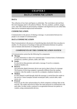
  • 1. CHAPTER 3 DATA COMMUNICATION DATA The collection of raw facts and figures is called data. The word data is derived from the Latin language and it is the plural of Datum. The text, numbers, symbols, images, voice, and video which are processed by computers and digital devices are called data. Data can be considered unprocessed information. COMMUNICATION Communication is the process of sharing a message. A conversation between two people is an example of communication. DATA COMMUNICATION Data Communication is the process of transferring data electrically from one place to another. It is the process of exchange of data and information between two parties such as humans and electronic or computing devices. COMPONENTS OF THE COMMUNICATION SYSTEM A Communication system has the following five components.  Message It is the information or data to be communicated. Common forms of information include text, numbers, pictures, audio, and video.  Sender It is the device that generates and sends a message. It can be a computer, telephone handset, etc.  Receiver Any particular digital electronic device can receive data in form of a message. The location of receiving computer is generally different from the sending computer. Like the sender, it can also be a computer, telephone handset, etc.  Medium It is the channel or path through which the message is carried from the sender to the receiver. Some examples include twisted-pair cable, coaxial cable, radio waves, etc.  Protocol Protocols are the rules and procedures by which computers exchange data on the network. The sender and receiver follow the same protocols to communicate with each other. In other words, a protocol is an agreement between two parties or vendors, using communication devices.
  • 2. STANDARDS Standards are the set of rules for data communication that are needed for the exchange of information among devices. It is important to follow Standards that are created by various Standard Organizations like IEEE, ISO, ANSI, etc. OR Standards are rules that define the appearance, functionality, or protocols of some equipment. They are essential for network communication. Network standards define rules of communication among computing devices. This ensures that companies (i.e. Cisco and IBM) that manufacture computing and networking products follow these uniform standards. By following standards, all hardware becomes compatible with the network, allowing efficient networking to take place. CHARACTERISTICS OF DATA TRANSMISSIONS Data communication has several characteristics but some are discussed below: 1. Signal type 2. Transmission mode 3. Direction of transmission 1. SIGNAL A signal is an electromagnetic or electrical current that carries data from one system or network to another. TYPES OF SIGNAL There are two types of signals discussed below:  Analog Signals Analog signals are continuously varying signals or waves that change with time and are used to represent data. An analog signal can be used to measure changes in some physical quantities such as light, sound, pressure, or temperature. Example An example of an analog signal is the human voice. When we speak, we use air to transmit an analog signal. An electrical signal from an audio tape can also be in analog form.  Characteristics Of Analog Signals  Amplitude The amplitude of a signal refers to the height of the signal. It is equal to the vertical distance from a given point on the waveform to the horizontal axis. It is measured in volts.  Frequency Frequency refers to the number of periods in one second or the number of cycles per second. Frequency is measured in Hertz (Hz).
  • 3.  Digital Signals A digital signal is an electrical signal that is converted into a pattern of bits to represent a sequence of discrete values, at any given time. It can only be one of the finite numbers represented as 0 or 1. Examples Examples of digital signals are Computers, Digital Phones, Digital pens, etc. DIFFERENCE BETWEEN ANALOG AND DIGITAL SIGNAL PARAMETERS ANALOG SIGNAL DIGITAL SIGNAL Definition An analog signal is a continuous wave that changes over time. A digital signal is a discrete wave that carries information in binary form. Range The Analog signal has no fixed range. Digital signal has an infinite number i.e. 0 and 1. Flexibility Analog hardware is not flexible. Digital hardware is flexible in implementation. Representation An analog signal is represented by a sine wave. A digital signal is represented by square waves Examples The human voice is an example of an analog signal. Signals used by the computer are the digital signal. 2. TRANSMISSION MODES (Asynchronous And Synchronous) Transmission is the action of transferring or moving something from one position or person to another. It is a mechanism for transferring data between two devices connected using a network. It is also called communication Mode. In computer networking there are two types of transmission:  Synchronous transmissions  Asynchronous transmissions  ASYNCHRONOUS TRANSMISSION In Asynchronous Transmission, data is sent in form of a byte or character. This transmission is the half-duplex type transmission. In this transmission start bits and stop bits are added to the data. It does not require synchronization.
  • 4. EXAMPLE  Email  Forums  Letters etc.  SYNCHRONOUS TRANSMISSION In Synchronous Transmission, data is sent in form of blocks or frames. This transmission is the full-duplex type. Between sender and receiver, synchronization is compulsory. In Synchronous transmission, There is no gap present between data. It is efficient and more reliable than asynchronous transmission to transfer a large amount of data. EXAMPLE  Chat Rooms  Telephonic Conversations  Video Conferencing etc. DIFFERENCES BETWEEN SYNCHRONOUS AND ASYNCHRONOUS TRANSMISSION SYNCHRONOUS TRANSMISSION ASYNCHRONOUS TRANSMISSION In Synchronous transmission, data is sent in form of blocks or frames. In Asynchronous transmission, data is sent in form of bytes or characters. Synchronous transmission is fast. Asynchronous transmission is slow. Synchronous transmission is costly Synchronous transmission is costly In Synchronous transmission, the time interval of transmission is constant. In Asynchronous transmission, the time interval of transmission is not constant, it is random. In this transmission, users have to wait till the transmission is complete before getting a response back from Here, users do not have to wait for the completion of transmission to get a response from the server.
  • 5. the server. In Synchronous transmission, there is no gap present between data. In Asynchronous transmission, there is a gap present between data. Efficient use of transmission lines is done in synchronous transmission. While in Asynchronous transmission, the transmission line remains empty during a gap in character transmission. The start and stop bits are not used in transmitting data. The start and stop bits are used in transmitting data that imposes extra overhead. Synchronous transmission needs precisely synchronized clocks for the information of new bytes. Asynchronous transmission does not need synchronized clocks as a parity bit is used in this transmission for information of new bytes. 3. DIRECTION OF TRANSMISSION Another characteristic of data transmission is direction Data may flow in more than one direction. There are three types of transmission modes. They are:  Simplex Mode  Half-duplex Mode  Full-duplex Mode  Simplex Mode Simplex is the data transmission mode in which the data can flow only in one direction, i.e., the communication is unidirectional. In this mode, a sender can only send data but can not receive it, and vice versa. OR In simplex mode, Sender can send the data but the sender can’t receive the data. It is unidirectional communication. Example Radio and TV transmission, keyboard, mouse, etc. Advantages  It utilizes the full capacity of the communication channel during data transmission.
  • 6.  It has the least or no data traffic issues as data flows only in one direction. Disadvantages  It is unidirectional having no inter-communication between devices.  There is no mechanism for information to be transmitted back to the sender(No mechanism for acknowledgment).  Half-Duplex Mode In half-duplex mode, each station can both transmit and receive, but not at the same time. When one device is sending, the other can only receive it, and vice versa. The half-duplex mode is used in cases where there is no need for communication in both directions at the same time. OR In half-duplex mode, Sender can send the data and also can receive the data one at a time. It is two-way directional communication but one at a time. Example Walkie-talkie in which message is sent one at a time and messages are sent in both directions. Advantages  Speed is a big advantage of a full-duplex.  The device can receive and send data, but not at the same time.  Troubleshooting is very easy  Data is transmitted on both sides Disadvantages  In a half Duplex, more data cannot be transmitted on both sides at the same time.
  • 7.  When one device sends data, the device on the other hand only receives data.  It is slow in data transmission.  Delay in data transmission.  Full-Duplex Mode In full-duplex mode, both stations can transmit and receive simultaneously. In full-duplex mode, signals going in one direction share the capacity of the link with signals going in another direction, this sharing can occur in two ways:  Either the link must contain two physically separate transmission paths, one for sending and the other for receiving.  Or the capacity is divided between signals traveling in both directions. OR In full-duplex mode, Sender can send the data and also can receive the data simultaneously. It is two-way directional communication simultaneously. Example: Telephone Network in which there is communication between two persons by a telephone line, through which both can talk and listen at the same time. Advantages  Performance of full-duplex mode is much better than half and simplex mode.  The speed of full-duplex mode is high than simplex and half-duplex mode.  Data can be sent and received on both sides, which increases the performance of the network.  No delay in communication, because both devices send and receive data at the same time. Disadvantages  No proper bandwidth utilization as the same line is used for sending and receiving data at the same time.  It is more complex than a simplex and half-duplex mode. DIFFERENCES BETWEEN THE TYPES OF TRANSMISSION MODES PARAMETERS SIMPLEX MODE HALF DUPLEX MODE FULL-DUPLEX MODE Direction Of Simplex mode is a Half Duplex mode Full-Duplex mode
  • 8. Communication uni-directional communication. is a two-way directional communication but one at a time. is a two-way directional communication simultaneously. Sender And Receiver In simplex mode, Sender can send the data but the sender can’t receive the data. In Half-duplex mode, Sender can send the data and also can receive the data one at a time. In Full-duplex mode, Sender can send the data and also can receive the data simultaneously. Channel Usage Usage of one channel for the transmission of data. Usage of one channel for the transmission of data. Usage of two channels for the transmission of data. Performance The simplex mode provides less performance than a half duplex and a full duplex. The Half-duplex mode provides less performance than the full duplex. Full-duplex provides better performance than simplex and half- duplex modes. Bandwidth Utilization Simplex utilizes the maximum of a single bandwidth. The Half-duplex involves lesser utilization of single bandwidth at the time of transmission. The Full-duplex doubles the utilization of transmission bandwidth. Examples Keyboard and monitor Walkie- talkie The walkie-talkie is an example of a half-duplex mode. The telephone network is an example of a full- duplex mode. DATA COMMUNICATION SPEED AND MEDIA BANDWIDTH Bandwidth is the maximum rate at which data transfer occurs across any particular path of the network. OR The data handling capacity of a media is referred to as its bandwidth. Bandwidth is the range of frequencies that is available for the transmission of data. There are some types of bandwidth are discussed below:  Narrowband The media communicate data at a relatively slow speed. Examples are telegraph lines.  Voice band These media are faster than narrowband. Most telephone lines that are used to carry microcomputer transmissions are voice bands.  Broadband These media transmit large volumes of data at high speed via microwave, satellite, coaxial cable, and fiber optics cable. It is also called a wind band. COMMUNICATION MEDIAS Communication media refers to the medium through which data transmission from the transmitter to the receiver takes place. The most common media for data
  • 9. communications are twisted-pair cable, coaxial cable, fiber optics cable, microwave, and satellite.  Twisted-Pair Cable Twisted pair cables were one of the earliest directed transmission media. A twisted pair cable is made up of two individual, insulated copper wires that are twisted together and run parallel. Usually 1mm in diameter, copper wires. Data is transmitted through one wire while ground reference is provided by the other. Reason for twisting All transmissions frequently experience noise, interference, and crosstalk. When the wires are twisted, some of the noise signals move together with the data signals while the other parts move in the other direction. The outside waves are canceled out by the unique twists. By computing the voltage difference between the two wires, the receiver can recover data. As a result, noise immunity is significantly improved.  Coaxial Cable An electrical cable containing a copper conductor, an insulator covering it, and a braided metal mesh that reduces crosstalk and signal interference is known as a coaxial cable. Coax is another name for coaxial cable. Coaxial cable offers much higher bandwidths and supports transmission speeds up to 10 megabits per second (Mbps). It can carry more data than older types of twisted pair cable. However, it is also expensive.  Fiber Optics Cable A fiber optic cable is made of glass or plastic and transmits signals in the structure of light signals. It involves an inner glass core surrounded by a glass cladding that reflects the light into the core. Each fiber is encircled by a plastic jacket. Semiconductor lasers transmit data in the form of light along with hair-thin glass fiber optic cables at the speed of light with no significant loss of intensity over very long distances. The system includes fiber optic cables that are made of tiny threads of glass or plastic. Advantages of Fiber Optic Cables The advantage of fiber optics cable are listed below:  Small Size and Lightweight The size of the optical fiber optic cables is minimal.  Easily available and low cost Silica glass is the substance used to make fiber optic cables. As a result, fiber optic cables are less expensive than cables with metallic conductors.  No electrical or electromagnetic interface The signal is unaffected by electrical or electromagnetic interference since the transmission uses light rays.  Large Bandwidth The fiber optic cable bandwidth is exceptionally wide since the light arrays operate at very high frequencies in the GHz range. This makes it possible to transmit more channels. As a result, a fiber optic cable has a substantially larger information-carrying capacity than a coaxial wire. Disadvantages of Fiber Optic Cables The disadvantage of fiber optics cable are listed below:  High Cost
  • 10. In comparison to other guided media, the cost of the cable and interfaces is higher.  Unidirectional light propagation Two-way communication requires either two fiber optic cables or two frequency bands on a single fiber because optical transmission is by nature unidirectional.  Installation and Maintenance fiber is different technology requiring skills; most engineers do not occupy. It is defined as fixed point-to-point ground installations.  Microwaves Microwave transmission is a line-of-sight transmission i.e. the sending and receiving antennas need to be properly aligned with each other. The distance covered by the signal is directly proportional to the height of the antenna. These are mostly used for mobile phone communications towers and television broadcasts. Terrestrial and Satellite are two types of microwave transmissions.  Terrestrial Terrestrial microwaves have both stations having antennas on earth.  Satellite In a satellite system, some antennas are on satellites in orbit and others are on stations on earth. They work at remote places so they can be used on mobile devices. COMMUNICATION HARDWARE MODEM A modem is short for Modulator and Demodulator. Modulation is the process of converting digital signals into analog signals. Demodulation is quite opposite; it converts analog signals into digital signals. The modem can send and receive signals that allow computers to share information. This sharing of information is possible over phone lines, cables, or satellite connections. Modulation Demodulation OSI MODEL The Open Systems Interconnection model is a conceptual model developed by ISO. It characterizes and standardizes the communication functions of a telecommunication and computing network. Its goal is the interoperability of different communication systems with standard communication protocols. This model divides a communication system into seven abstraction layers.  Application Layer This layer enables users to access the network with applications such as email, file transfer, etc. These applications produce the data, which is transferred over the network.  Presentation Layer It receives information from the application layer and converts it to a uniform network format (ASCII or Unicode) which is acceptable by the rest of the OSI model and destination. Encryption and decryption are also the
  • 11. responsibility of this layer. This layer also reduces the number of transfer bits by compression.  Session Layer This layer establishes, maintains, and ends a session or logical connection between applications on two computers. It manages who can transmit data at a certain time and for how long. This layer adds checkpoints. If the session fails only data after the most recent checkpoint need to be transmitted.  Transport Layer It ensures the reliable transmission of data. The transport layer manages error control, ow control, and quality of the service. If the data is not properly transmitted it requests to be resent.  Network Layer The function of this layer is the selection of the shortest and most suitable path from source to destination, from the number of routes available. It is also responsible to convert logical addresses (IP addresses) to physical addresses (MAC addresses).  Data Link Layer This layer is responsible to transmit data using physical addresses. The data link layer ensures error free transmission of packets. The packet in this layer is referred to as the frame.  Physical Layer It is responsible for converting electrical signals into bits. It also defines the cable types to be used as transmission media, cards, topology, and other physical aspects.