Isweek so d2-960 limiting current type sensor oxygen sensors - so-d2-960-a100 c a300c
•
0 j'aime•308 vues

Measuring gas: Oxygen concentration Measuring medium: Gaseous atmosphere Measuring principle: Limiting current type sensor Measuring ranges: 1.00 – 96.0 vol.% O2 http://www.isweek.com/product/so-d2-960-limiting-current-type-sensor-oxygen-sensors-so-d2-960-a100c-a300c_2115.html Model Number: SO-D2-960-A100C / A300C
![Characteristic Data:
Measuring gas
Oxygen concentration
Measuring medium
Gaseous atmosphere
Measuring principle
Limiting current type sensor
Measuring ranges
Type SO-xx-001 10 ppm – 1000 ppm O2
Type SO-xx-010 0,01 – 1,0 vol.% O2
Type SO-xx-020 0,01 – 2,0 vol.% O2
Type SO-xx-050 0,05 – 5,0 vol.% O2
Type SO-xx-250 0,10 – 25,0 vol.% O2
Txpe SO-xx-960 1,00 – 96,0 vol.% O2
Details see paragraph: specifications
Output characteristic:
Is (O2) Sensor current in A
[O2] Oxygen concentration in %
k specific constant of sensor
Response time (t90)
2 to 25 sec. (Depends on: sensor type, gas flow, measuring chamber)
Sensor voltage / heating voltage / power consumption / heater cold resistance
Sensor voltage: 0,7 to 1,6 Volt
Heating voltage: 3.6 – 4.4 Volts
Power consumption: 1.3 to 1.8 Watts (depends on application and packaging)
Cold resistance: R(25°C) = 3.25 0.20
Warm up time
Min. 30 s
Maximum permissible operating temperature
350 °C (*)
*Depending on the cable and filter assembly (see paragraph: specification, Cable assembly)
Permissible volumetric flow rate (Purging the sensor)
For all sensor types, the maximum flow rate depends on the way of purging the sensor (sensor in direct gas flow, gas beam shape,
etc.) and the size of the measuring chamber. Exception: SO-E1-xxx (TO8 + hose connection for direct gassing). Permissible flow
[ml/min]: 100 - 500 (optimal: 250)
Lifetime (MTTF)
~ 20.000 hours (*)
* Depending on measuring medium. Stated lifetime refers to a heated, operated sensor of type SO-xx-250 and SO-xx-960. A failure or
reaching the lifetime typically means a slight deviation from the dispatch specifications.
Vibration resistance
Sensors based on the TO8 socket as well as those built with a TO39 socket (SO-Bx-xxx, SO-Ex-xxx, SO-Ax-xxx) meet the European
Norm EN60068-2-6 (Sinusoidal vibration tests).
100
][
1ln)( 2
2
O
kOIs](data:image/gif;base64,R0lGODlhAQABAIAAAAAAAP///yH5BAEAAAAALAAAAAABAAEAAAIBRAA7)
Recommandé
Contenu connexe
En vedette
En vedette (18)
Dernier
Dernier (20)
Isweek so d2-960 limiting current type sensor oxygen sensors - so-d2-960-a100 c a300c
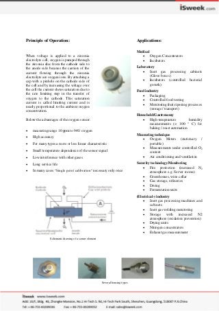
- 1. Principle of Operation: When voltage is applied to a zirconia electrolyte cell, oxygen is pumped through the zirconia disc from the cathode side to the anode side because the carriers of the current flowing through the zirconia electrolyte are oxygen ions. By attaching a cap with a pinhole on the cathode side of the cell and by increasing the voltage over the cell the current shows saturation due to the rate limiting step in the transfer of oxygen to the cathode. This saturation current is called limiting current and is nearly proportional to the ambient oxygen concentration. Below the advantages of the oxygen sensor: measuring range 10 ppm to 96% oxygen High accuracy For many types a more or less linear characteristic Small temperature dependence of the sensor signal Low interference with other gases Long service life In many cases “Single point calibration“ necessary only once Schematic drawing of a sensor element Applications: Medical Oxygen Concentrators Incubators Laboratory Inert gas processing cabinets (Glove boxes) Incubators (controlled bacterial growth) Food industry Packaging Controlled food testing Monitoring fruit ripening processes (storage / transport) Household/Gastronomy High-temperature humidity measurements (> 100 ° C) for baking / roast automation Measuring technique Oxygen Meters (stationary / portable) Measurements under controlled O2 content Air conditioning and ventilation Security technology/Monitoring Fire protection (increased N2 atmosphere e.g. Server rooms) Greenhouses, wine cellar Gas storage, refineries Diving Fermentation units (Electrical-) industry Inert gas processing machines and cabinets Inert gas welding monitoring Storage with increased N2 atmosphere (oxidation prevention) Drying units Nitrogen concentrators Exhaust gas measurement Several housing types
- 2. Characteristic Data: Measuring gas Oxygen concentration Measuring medium Gaseous atmosphere Measuring principle Limiting current type sensor Measuring ranges Type SO-xx-001 10 ppm – 1000 ppm O2 Type SO-xx-010 0,01 – 1,0 vol.% O2 Type SO-xx-020 0,01 – 2,0 vol.% O2 Type SO-xx-050 0,05 – 5,0 vol.% O2 Type SO-xx-250 0,10 – 25,0 vol.% O2 Txpe SO-xx-960 1,00 – 96,0 vol.% O2 Details see paragraph: specifications Output characteristic: Is (O2) Sensor current in A [O2] Oxygen concentration in % k specific constant of sensor Response time (t90) 2 to 25 sec. (Depends on: sensor type, gas flow, measuring chamber) Sensor voltage / heating voltage / power consumption / heater cold resistance Sensor voltage: 0,7 to 1,6 Volt Heating voltage: 3.6 – 4.4 Volts Power consumption: 1.3 to 1.8 Watts (depends on application and packaging) Cold resistance: R(25°C) = 3.25 0.20 Warm up time Min. 30 s Maximum permissible operating temperature 350 °C (*) *Depending on the cable and filter assembly (see paragraph: specification, Cable assembly) Permissible volumetric flow rate (Purging the sensor) For all sensor types, the maximum flow rate depends on the way of purging the sensor (sensor in direct gas flow, gas beam shape, etc.) and the size of the measuring chamber. Exception: SO-E1-xxx (TO8 + hose connection for direct gassing). Permissible flow [ml/min]: 100 - 500 (optimal: 250) Lifetime (MTTF) ~ 20.000 hours (*) * Depending on measuring medium. Stated lifetime refers to a heated, operated sensor of type SO-xx-250 and SO-xx-960. A failure or reaching the lifetime typically means a slight deviation from the dispatch specifications. Vibration resistance Sensors based on the TO8 socket as well as those built with a TO39 socket (SO-Bx-xxx, SO-Ex-xxx, SO-Ax-xxx) meet the European Norm EN60068-2-6 (Sinusoidal vibration tests). 100 ][ 1ln)( 2 2 O kOIs
- 3. Pin connection for different sensor types Standard housing TO39 (Type SO-A0-xxx), TO8 (Type SO-Bx-xxx) 1 H+ (HS+) 2 H- (HS-) 3 Sen+ 4 Sen- (Pin-side view) Sensors with connecting cable for 4-wire operation (SO-Bx-xxx-AxxxC, SO-Dx-xxx-AxxxC) Sensors with connecting leads (teflon isolation with temperature stability up to 250 °C): Schematic drawing of sensor connection cable with plug, view from backside of the plug Cable colour Pin Connection Connected to pin No. Violet 1 Violet 2 H+ HS+ 1 White 1 White 2 H- HS 2 Red Sen+ 3 Black Sen- 4
- 4. Specification: Housing types Type Housing Dimensions, remarks SO-A0-xxx TO39 9.2 mm; H= 6.4 mm; pin distance 3.59 mm SO-B0-xxx SO-E2-xxx TO8 15.3 mm; H= 13.7 mm; pin distance 7.18 mm SO-B1-xxx TO8 + mounting flange 15.3 mm; H= 13.7 mm; pin distance 7.18 mm; mounting holes (flange): 3.4 mm, distance 36 mm SO-D0-xxx- xxxxx Screw mountable housing with sintered metal top M 16 * 1.5 mm L tot.= 49 mm; with connection cable sintered metal top 12 mm, L= 20 mm, SW22 SO-D1-xxx- xxxxx Screw mountable housing with sintered metal top M 10 * 1 mm L tot.= 43 mm; with connection cable sintered metal top 12 mm, L= 20 mmm SW10 SO-D2-xxx- xxxxx Aluminium-screw-mountable housing with sintered metal filter M 16 * 1.5 mm L tot.= 47.4 mm; with connection cable sintered metal filter 12.5 mm, SW22 SO-E1-xxx TO8 with hose connection 15,3 mm; H= 23,9 mm; pin distance 7,18 mm; hose connection 4,8 mm Cable assembly Type Cable length [cm] Operating temperature[°C] Plug connector SO-xx-xxx none 350 none Except: SO-E1-xxx none 250 (*) none SO-xx-xxx-A100C SO-xx-xxx-A300C 100 300 200 (*) 200 (*) Rast 2,5 Rast 2,5 * Operating temperature of the sensor is limited by the temperature resistance of the cable assembly or by the use of an optional Teflon filter. Measuring ranges Sensor type Measuring range Output current at gas composition Sensor voltage Code SO-xx-001 10 ppm O2 – 1000 ppm O2 70 A – 140 A 400 ppm O2 ,remainder N2 0.70 volt A SO-xx-010 0.01 % O2 – 1.0 % O2 150 A – 250 A 1.0 % O2 , remainder N2 0.75 volt H SO-xx-020 0.01 % O2 – 2.0 % O2 150 A – 250 A 2.0 % O2 , remainder N2 0.75 volt B SO-xx-050 0.05 % O2 – 5.0 % O2 150 A – 250 A 5.0 % O2 , remainder N2 0.80 volt C SO-xx-250 0.10 % O2 – 25.0 % O2 100 A – 200 A 20.9 % O2 , remainder N2 (air) 0.85 volt D SO-xx-960 1.00 % O2 – 96.0 % O2 15 A – 30 A 20.9 % O2 , remainder N2 (air) 1.60 volt E * Operation outside the specified measuring range can cause a permanent damage of the electrode. Accuracy, reproducibility and response time Sensor type Accuracy Reproducibility SO-xx-001 (*) 20 ppm O2 < 10 ppm O2 SO-xx-010 100 ppm O2 < 100 ppm O2 SO-xx-020 200 ppm O2 < 100 ppm O2 SO-xx-050 500 ppm O2 < 250 ppm O2 SO-xx-250 0.25 % O2 < 0.1 % O2 SO-xx-960 1.00 % O2 < 0.2 % O22 * Currently SO-D2-001 not available Temperature of the housing during operation Type Housing Max. temperature SO-Ax-xxx TO39 250 °C SO-Bx-xxx TO8 70 °C SO-Dx-xxx-xxxxx Screw mounted housing 70 °C (Measured at ambient temperature of 25°C)
- 5. Appendix: Housing types Standard housings: TO39 (SO-A0-xxx) TO8 (SO-B0-xxx) Screw mountable housings with sintered metal cap SO-D0-xxx- xxxxx SO-D1-xxx- xxxxx
- 6. Aluminium Screw mountable housings with sintered metal filter SO-D2-xxx- xxxxx (SW22) TO8 housing with mounting flange TO8 housing with hose connection (direct exposure to gas) SO-B1-xxx- xxxxx SO-E1-xxx