SlideShare une entreprise Scribd logo
1  sur  192
Télécharger pour lire hors ligne
1
Industrial Training Project Report
On
“Coal - Fired Steam Power Plants”
National Thermal Power Corporation SIMHADRI (Visakhapatnam)
(Submitted towards completion of industrial training at NTPC SIMHADRI)
Under the guidance of: Submitted by:
Shri B.Venkata Rao, Uppu Ashish,
DGM, Ash Handling Plant, B.Tech, Mechanical Engg.
NTPC SIMHADRI, (4th
sem),
Visakhapatnam. GITAM University,
Visakhapatnam.
2
TRAINING SCHEDULE
DEPARTMENT PERIOD
BOILER MAINTAINANCE
11.05.2015
to
16.05.2015
TURBINE MAINTAINANCE
18.05.2015
to
23.05.2015
OFFSITE MAINTAINANCE
25.05.2015
to
30.05.2015
ASH HANDLING PLANT
01.06.2015
to
09.06.2015
3
CERTIFICATE
This is to certify that UPPU ASHISH, a student of 2012-2016 Batch
of B.Tech,Mechanical Engineering in 4th
Year of GITAM University,
Visakhapatnam has successfully completed his industrial training at
NTPC Simhadri, Visakhapatnam for four weeks from 7th
May to 9th
June 2015. He has completed the whole training as per the training
report submitted by him.
HR Manager
NTPC Simhadri,
Visakhapatnam
4
Acknowledgment
“It is not possible to prepare a project report without the assistance &
encouragement of other people. This one is certainly no exception.”
On the very outset of this report, I would like to extend my sincere &
heartfelt obligation towards all the personages who have helped me in
this endeavor. Without their active guidance, help, cooperation &
encouragement, I would not have made headway in the industrial
training
I am ineffably indebted to Mr. K.N. Reddy, AGM (MM-BMD); Mr.
D.Shravan, Dy. Manager (BMD-PP); Mr. Piyush Kanwar, Dy. Manager
(BMD-Mills); Mr. Balaji, Dy. Manager (BMD-RM); Mr. T.Prem Das, AGM
(MM-TMD & OS); Mr. Shridhar, Dy. Manager (MM-TMD) for
conscientious and encouragement to accomplish this assignment.
I am extremely thankful and pay my gratitude to my guide Mr. B.Venkata
Rao for his valuable guidance and support on completion of this project
in its presently.
I extend my gratitude to NTPC Ltd Simhadri and HR-EDC Dept. of NTPC
Ltd Simhadri for giving me this opportunity.
I also acknowledge with a deep sense of reverence, my gratitude
towards my parents, who has always supported me morally as well as
economically.
Any omission in this brief acknowledgement does not mean lack of
gratitude.
Thanking You
Ashish Uppu
5
TABLE OF CONTENTS
1. About NTPC……………………………………………… 6
2. About NTPC SIMHADRI……………………………. 14
3. NTPC power stations in India…………………… 18
4.Principal and Operation of a Thermal Power
Plant…………………………………………………………. 19
5.Principal components of a 500MW Thermal
Power Plant………………………………………………. 29
6.The Layout of NTPC Simhadri……………………. 45
7.Boiler and its auxiliaries……………………………. 48
8.The Steam Turbine Theory……………………… 118
9. Turbine and its auxiliaries……………………… 128
10. DM treatment
plant……………………………………………………….. 161
11. Cooling Towers…………………………………. 169
12. Circulating Water System…………………. 174
13. Principal components of CWS………….. 178
14. Ash Handling System……………………….. 183
15. Ways to increase the thermal efficiency of
power plants………………………………………….. 187
16. Losses during operation & maintenance of
a power plant…………………………………………. 190
6
About NTPC
NTPC Limited is the largest thermal power generating company of
India, Public Sector Company. It was incorporated in the year 1975 to
accelerate power development in the country as a wholly owned
company of the Government of India. NTPC is emerging as a diversified
power major with presence in the entire value chain of the power
generation business. Apart from power generation, which is the mainstay
of the company, NTPC has already ventured into consultancy, power
trading, ash utilization and coal mining. NTPC ranked 341st in the ‘2010,
Forbes Global 2000’ ranking of the World’s biggest companies. NTPC
became a Maharatna company in May, 2010, one of the only four
companies to be awarded this status.
Within a span of 31 years, NTPC has emerged as a truly national
power company, with power generating facilities in all the major regions of the
country. NTPC's core business is engineering, construction and operation
of power generating plants and providing consultancy to power utilities in
India and abroad.
The total installed capacity of the company is 31134 MW (including JVs)
with 15coal based and 7 gas based stations, located across the country.
In addition under JVs, 3 stations are coal based & another station uses
7
naphtha/LNG as fuel. By 2017, the power generation portfolio is
expected to have a diversified fuel mix with coal based capacity of
around 53000 MW, 10000 MW through gas, 9000 MW through Hydro
generation, about 2000 MW from nuclear sources and around 1000MW
from Renewable Energy Sources (RES). NTPC has adopted a multi-
pronged growth strategy which includes capacity addition through green
field projects, expansion of existing stations, joint ventures, subsidiaries
and takeover of stations.
NTPC has been operating its plants at high efficiency levels. Although the
company has 18.79% of the total national capacity it contributes 28.60%
of total power generation due to its focus on high efficiency. NTPC’s
share at 31 Mar 2001of the total installed capacity of the country was
24.51% and it generated 29.68%of the power of the country in 2008-09. Every
fourth home in India is lit by NTPC.170.88BU of electricity was produced by its
stations in the financial year 2005-2006. The Net Profit after Tax on March
31, 2006 was INR 58,202 million. The Net Profit after Tax for the quarter
ended June 30, 2006 was INR 15528 million, which is 18.65% more than
for the same quarter in the previous financial year. 2005). NTPC is as
second best utility in the world.
In October 2004, NTPC launched its Initial Public Offering (IPO)
consisting of 5.25% as fresh issue and 5.25% as offer for sale by
Government of India. NTPC thus became a listed company in November
2004 with the Government holding 89.5% of the equity share capital. In
February 2010, the Shareholding of Government of India was reduced
from 89.5% to 84.5% through Further Public Offer and the balance 10.5%
is held by FIIs, Domestic Banks, Public and others.
8
NTPC Limited
Type Public
Founded 1975
Headquarters Delhi, India
Key people R S Sharma, Chairman & Managing Director
Industry Electricity generation
Products Electricity
Revenue INR 416.37 billion (2008)
Net income INR 70.47 billion (2008)
Employees 23867 (2006)
Website http://www.ntpc.co.in
8
NTPC Limited
Type Public
Founded 1975
Headquarters Delhi, India
Key people R S Sharma, Chairman & Managing Director
Industry Electricity generation
Products Electricity
Revenue INR 416.37 billion (2008)
Net income INR 70.47 billion (2008)
Employees 23867 (2006)
Website http://www.ntpc.co.in
8
NTPC Limited
Type Public
Founded 1975
Headquarters Delhi, India
Key people R S Sharma, Chairman & Managing Director
Industry Electricity generation
Products Electricity
Revenue INR 416.37 billion (2008)
Net income INR 70.47 billion (2008)
Employees 23867 (2006)
Website http://www.ntpc.co.in
9
Strategies of NTPC
Technological Initiatives
 Introduction of steam generators (boilers) of the size of 800 MW.
 Integrated Gasification Combined Cycle (IGCC) Technology.
 Launch of Energy Technology Centre -A new initiative for
development of technologies with focus on fundamental R&D.
 The company sets aside up to 0.5% of the profits for R&D.
 Roadmap developed for adopting μClean Development.
 Mechanism to help get / earn μCertified Emission Reduction.
10
Corporate Social Responsibility
 As a responsible corporate citizen NTPC has taken up number of
CSR initiatives.
 NTPC Foundation formed to address Social issues at national
level
 NTPC has framed Corporate Social Responsibility Guidelines
committing up to 0.5% of net profit annually for Community
Welfare.
 The welfare of project affected persons and the local population
around NTPC projects are taken care of through well drawn
Rehabilitation and Resettlement policies.
 The company has also taken up distributed generation for remote
rural areas
Partnering government in various initiatives
 Consultant role to modernize and improvise several plants across
the country.
 Disseminate technologies to other players in the sector.
 Consultant role Partnership in Excellence Programme for
improvement of PLF of 15 Power Stations of SEBs.
 Rural Electrification work under Rajiv Gandhi Garmin Vidyutikaran.
Environment management
 All stations of NTPC are ISO 14001 certified.
 Various groups to care of environmental issues.
 The Environment Management Group.
 Ash tilization Division.
 Afforestation Group.
 Centre for Power Efficiency & Environment Protection.
 Group on Clean Development Mechanism.
11
 NTPC is the second largest owner of trees in the country after
the Forest department.
Vision
“To be the world’s largest and best power producer, powering India’s
growth.”
Mission
“Develop and provide reliable power, related products and services
at competitive prices, integrating multiple energy sources with
innovative and eco-friendly technologies and contribute to society.”
Core Values – BE COMMITTED
B Business ethics
E Environmentally and Economically Sustainable
C Customer Focus
O Organizational and Professional Pride
M Mutual Respect and Trust
M Motivating Self and Others
I Innovation and Speed
T Total Quality for Excellence
T Transparent and Respected Organization
E Enterprising
D Devoted
12
Journey of NTPC
12
Journey of NTPC
12
Journey of NTPC
13
A Qualitative study of the Company
14
About NTPC Simhadri
Simhadri Super Thermal Power Plant is a coal-fired power plant
located in the Visakhapatnam district of the Indian state of Andhra
Pradesh. The power plant is one of the coal fired power plants of NTPC,
a Government of India enterprise. The coal for the power plant is
sourced from Kalinga Block of Talcher Coal fields in Odisha. Power
generated by units 1 and 2, making up for 1,000 MW, is dedicated to
power distribution companies owned by the Government of Andhra
Pradesh. The remainder 1,000 MW, generated by units 3 and 4, is
allocated to the states of Odisha, Tamil Nadu, and Karnataka. Their
shares are decided arbitrarily, with unsold power being sold to Andhra
Pradesh.
NTPC Simhadri is a modern coal-fired power plant, and is a combination
of four independent generation units, with common water and fuel
sources, and common ash ponds. Each of the four units has a
nameplate capacity of 500 MW. Units 1 and 2 were built in the first
phase of development, and were commissioned in February 2002 and
15
August 2004, respectively, to meet urgent needs of power in the largely
agrarian Coastal Andhra and North-Coastal Andhra regions. Units 3 and
4 were built in the second phase, and commissioned in March 2011 and
March 2012, respectively. Since the operator of this plant is a
Government of India enterprise, and since the plant was built with
central government funds, power generated by units 3 and 4 are sold to
distribution companies based in neighboring states of Odisha, Tamil
Nadu, and Karnataka, over the National Grid, as power stocks. The
allocations are decided between NTPC and the three states' discoms.
Unsold units are offered to discoms of Andhra Pradesh for purchase at
market prices.
Coal for NTPC Simhadri is sourced from Talcher Coal Fields, Odisha,
and transported by East Coast Railway (ECoR), over the Kolkata-
Chennai trunk line, with a spur heading towards the plant at Duvvada.
NTPC Simhadri uses fresh water sourced from the Yeluru Canal as
working fluid (steam which turns the turbines). For cooling, however, the
plant uses seawater pumped in from the Bay of Bengal. Seawater, with
its salt content, is unfit to be used as working fluid, without desalination.
16
PROJECT PROFILE
Approved Capacity 2000 MW (4 X 500 MW)
Location Paravada Mandal, Visakhapatnam, AP
Source of Finance JBIC Loan and Internal Resources
Fuel Source Mahanadi Coal Fields, Talcher
Fuel Requirement 5.04 Million Tons of Coal per annum
Mode of Transportation Rail
DM Water Source Water from Yelluru Canal
Sweet Water Requirement 600 m3
/ hr
Cooling Water Source Sea Water from Bay of Bengal
Sea Water Requirement 9100 m3
/ hr
Main Contractor M/s BHEL
Power Evacuation AP TRANSCO (Via Kalpaka)
Beneficiary State Andhra Pradesh
17
Salient Features of NTPC Simhadri
• First Coastal Based Coal fired thermal Power Project of NTPC
• Biggest Sea Water Intake-Well in India (For Drawing Sea Water
from Bay of Bengal)
• Use of Sea Water for Condenser Cooling and Ash Disposal
• Asia’s Tallest Natural Cooling Towers (165 m), 6th in the
World
• Use of Fly-Ash Bricks in the Construction of all Buildings
• Coal Based Project of NTPC Whose Entire Power is allocated to
Home State (AP)
• Use of Monitors and Large Video Screens (LVS) as Man Machine
Interface (MMIs) for Operating the Plant
• Use of Process Analysis, Diagnosis and Optimization (PADO) for the
first time in NTPC
• Flame Analysis of Boiler by Dedicated Scanners for all Coal
Burners
• Boiler Mapping By Acoustic Pyrometers
• Use of Distributed Digital Control and Management Information
System (DDCMIS)
• Totally Spring Loaded Floating Foundation for all Major
Equipments Including TG
• Use of INERGEN as Fire Protection System for the 1st time in
NTPC
• Use of Digital Automatic Voltage Regulator (DAVR)
• Use of VFD in ID Fan
18
NTPC POWER STATIONS IN INDIA
18
NTPC POWER STATIONS IN INDIA
18
NTPC POWER STATIONS IN INDIA
19
Principle and Operation of a Thermal Power
Plant
Principle:
Any Steam Power Plant operates under the Simple Rankine Cycle.
Hence the Rankine cycle is often termed as Basic Power Plant Cycle.
The Rankine Cycle
The Rankine cycle is a thermodynamic cyclewhich converts heat into
work. The heat is supplied externally to a closed loop, which usually uses
water as the working fluid. This cycle generates about 80% of all electric
power used throughout the world, including virtually all solar, thermal,
biomass, coal and nuclear power plants. It is named after William John
Macquorn Rankine,aScottish polymath. The thermal (steam) power plant
uses a dual (vapour+liquid) phase cycle. It is a closed cycle to enable
the working fluid (water) to be used again and again.
The basic principle of the working of a Thermal Power Plant is quite
simple. The fuel used in the plant is burnt in the boiler, and the heat
generated is then used to boil water which is circulated through several
Layout of a Simple
Rankine Cycle
T-S diagram of a Simple
Rankine Cycle
20
tubes, the steam that is generated is used to drive a turbine, which in
turn is coupled with a generator, which then produces the electricity.
A Rankine cycle describes a model of the operation of steam heat
engines most commonly found in power generation plants. Common
heat sources for power plants using the Rankine cycle are coal, natural gas,
oil, and nuclear. The Rankine cycle is sometimes referred to as a practical
Carnot cycle as, when an efficient turbine is used, the TS diagram will
begin to resemble the Carnot cycle. The main difference is that a pump
is used to pressurize liquid instead of a gas. This requires about 1/100th
(1%) as much energy as that compressing a gas in a compressor (as in the
Carnot cycle).The efficiency of a Rankine cycle is usually limited by the
working fluid. Without the pressure going super critical the temperature
range the cycle can operate over is quite small, turbine entry
temperatures are typically 565°C (the creep limit of stainless steel) and
condenser temperatures are around 30°C. This gives a theoretical
Carnot efficiency of around 63% compared with an actual efficiency of
42% for a modern coal-fired power station. This low turbine entry
temperature (compared with a gas turbine) is why the Rankine cycle is
often used as a bottoming cycle in combined cycle gas turbine power stations.
The working fluid in a Rankine cycle follows a closed loop and is re-used
constantly. The water vapor and entrained droplets often seen billowing
from power stations is generated by the cooling systems (not from the
closed loop Rankine power cycle) and represents the waste heat that
could not be converted to useful work.
Note that cooling towers operate using the latent heat of vaporization of
the cooling fluid. The white billowing clouds that form in cooling tower
operation are the result of water droplets which are entrained in the
cooling tower airflow; it is not, as commonly thought, steam. While many
substances could be used in the Rankine cycle, water is usually the fluid
21
of choice due to its favorable properties, such as nontoxic and un
reactive chemistry, abundance, and low cost, as well as its thermodynamic
properties. One of the principal advantages it holds over other cycles is
that during the compression stage relatively little work is required to drive
the pump, due to the working fluid being in its liquid phase at this point.
By condensing the fluid to liquid, the work required by the pump will only
consume approximately 1% to 3% of the turbine power and so give a
much higher efficiency for a real cycle. The benefit of this is lost
somewhat due to the lower heat addition temperature. Gas turbines, for
instance, have turbine entry temperatures approaching 1500°C.
Nonetheless, the efficiencies of steam cycles and gas turbines are fairly well
matched.
Ts diagram of a typical Rankine cycle operating between pressures of
0.06bar and 50bar.
There are four processes in the Rankine cycle, each changing the state
of the working fluid. These states are identified by number in the diagram
to the right
T-S diagram of a Typical
Rankine cycle
22
I. Process 1-2: The working fluid is pumped from low to high
pressure, as the fluid is a liquid at this stage the pump requires
little input energy.
II. Process 2-3: The high pressure liquid enters a boiler where it is
heated at constant pressure by an external heat source to become
a dry saturated vapor.
III. Process 3-4: The dry saturated vapor expands through a turbine,
generating power. This decreases the temperature and pressure of
the vapor and some condensation may occur.
IV. Process 4-1: The wet vapor then enters a condenser where it is
condensed at a constant pressure and temperature to become a
saturated liquid. The pressure and temperature of the condenser is
fixed by the temperature of the cooling coils as the fluid is
undergoing a phase-change.
In an ideal Rankine cycle thepumpand turbine would be isentropic, i.e.,
the pump and turbine would generate no entropy and hence maximize
the net work output processes1-2and 3-4 would be represented by vertical lines
onthe Ts diagram. The Rankine cycle shown here prevents the vapor
ending up in the superheat region after the expansion in the turbine,
which reduces the energy removed by the condensers.
In a real Rankine cycle, the compression by the pump and the
expansion in the turbine are not isentropic. In other words, these
processes are non-reversible and entropy is increased during the two
processes. This somewhat increases the power required by the pump
and decreases the power generated by the turbine. In particular the
efficiency of the steam turbine will be limited by water droplet formation. As
thewater condenses, water droplets hit the turbine blades at high speed
causing pitting and erosion, gradually decreasing the life of turbine
23
blades and efficiency of the turbine. The easiest way to overcome this
problem is by superheating the steam. On the Ts diagram above, state 3
is above a two phase region of steam and water so after expansion the
steam will be very wet. By superheating, state 3 will move to the right
of the diagram and hence produce a dryer steam after expansion.
Rankine Cycle with Reheat
In this two turbines work in series on a common shaft. The first accepts
vapor from the boiler at a high pressure. After the vapor has passed
through the first turbine (also referred as H.P turbine), it renters the
boiler and is reheated before it is allowed to pass through the second
turbine (often referred to as L.P turbine).It prevents the vapor from
condensing during its expansion which can intensely damage the turbine
blades, and improves the efficiency of the cycle by decreasing the net
work output. To protect the reheat tubes, steam is not allowed to expand
Rankine Cycle with superheating
24
deep into the two-phase region before it is taken for reheating, because
in that case the moisture particles in the steam while evaporating would
leave behind solid deposits in the form of scale which is difficult to
remove. A low reheat pressure may bring down the cycle efficiency.
Again, a high reheat pressure increases the moisture content at turbine
exhaust. Thus the reheat pressure is optimized. By increasing the
number of reheats, still higher steam pressures could be used, but
mechanical stresses increase at a higher proportion then the increase in
pressure, also increase. Hence more than two reheats have not been
used so far.
Regenerative Rankine Cycle
The main aim of the Regenerative Rankine cycle is to improve the cycle
efficiency by decreasing the net heat input. In Regenerative Rankine
cycle, after emerging from the condenser (possibly as a sub cooled
liquid) the working fluid is heated by steam tapped from the hot portion
of the cycle (i.e. from the intermediate stages of the turbine). On the
Rankine Cycle with Reheat
25
diagram shown, the fluid at 2 is mixed with the fluid at 4 (both at the
same pressure) to end up with a saturated liquid at 7.
Reheat-Regenerative Cycle
The reheating of steam is adopted when the vaporization pressure is
high. The effect of reheat alone on the thermal efficiency of the cycle is
very small. Regeneration or the heating up of feed water by steam
extracted from the turbine has a marked effect on cycle efficiency. The
Reheat-Regenerative Rankine cycle (with minor variants) is commonly
used in modern steam power stations. Another variation is where 'bleed
steam' from between turbine stages is sent to feed water heaters to
preheat thewateronits way from the condenser to the boiler.
Regenerative Rankine Cycle
26
Factors affecting thermal cycle efficiency
1. Initial steam pressure
2. Initial steam temperature
3. Reheat pressure and temperature, if reheat is used
4. Condenser pressure
5. Regenerative feed water heating
Operation-Fundamentals of Coal to Electricity:
Reheat – Regenerative Rankine
Cycle
Operation of a Steam Power Plant
27
28
MM
Mechanical Power to Electric Power
As the blades of the turbine rotate, the shaft of the generator which is coupled to that of the
turbine also rotates .It causes rotation of the exciter which produces an induced emf
(electric power)
29
Principle components of a 500MW thermal
power plant
Any 500MW thermal power plant comprises of the following
components:
1. Cooling tower
2. Cooling water pump
3. Transmission line (3-phase)
4. Unit transformer (3-phase)
5. Electric generator (3-phase)
6. Low pressure turbine
7. Feed Water Pump
A typical 500MW Thermal Power
Plant
30
8. Condenser
9. Intermediate pressure turbine
10. Steam governor valve
11. High pressure turbine
12. Deaerator
13. Feed heater
14. Coal conveyor
15. Coal hopper
16. Pulverized coal mill
17. Boiler drum
18. Ash hopper
19. Super heater
20. Forced draught fan
21. Re heater
22. Air intake tower
23. Economizer
24. Air pre heater
25. Electrostatic Precipitator (ESP)
26. Induced draught fan
27. Flue Gas
1. Cooling Tower
Cooling towers are heat removal devices used to transfer process
waste heat to the atmosphere. Cooling towers may either use the
evaporation of water to remove process heat and cool the working
fluid to near the wet-bulb air temperature or in the case of closed
circuit dry cooling towers rely solely on air to cool the working fluid to
near the dry-bulb air temperature. However, evaporative type cooling
31
towers are most commonly used. Common applications include
cooling the circulating water used in oil refineries, chemical plants,
power stations and building cooling. The towers vary in size from
small roof-top units to very large hyperboloid structures that can be
up to 200 meters tall and 100 meters in diameter, or rectangular
structures that can be over 40 meters tall and 80 meters long.
Smaller towers are normally factory-built, while larger ones are
constructed on site. The absorbed heat is rejected to the atmosphere
by the evaporation of some of the cooling water in mechanical
forced-draft or induced Draft towers or in natural draft hyperbolic
shaped cooling towers as seen at most nuclear power plants.
2. Cooling Water Pump
It pumps the water from the cooling tower to the condenser.
3. Three Phase Transmission line
Three phase electric power is a common method of electric power
transmission. It is a type of polyphase system mainly used to power
motors and many other devices. A three phase system uses less
conductive material to transmit electric power than equivalent single
phase, two phase, or direct current system at the same voltage. In a
three phase system, three circuits reach their instantaneous peak
values at different times. Taking current in one conductor as the
reference, the currents in the other two are delayed in time by one-
third and two-third of one cycle .This delay between “phases” has the
effect of giving constant power transfer over each cycle of the current
and also makes it possible to produce a rotating magnetic field in an
electric motor. At the power station, an electric generator converts
mechanical power into a set of electric currents, one from each
32
electromagnetic coil or winding of the generator. The current are
sinusoidal functions of time, all at the same frequency but offset in
time to give different phases. In a three phase system the phases are
spaced equally, giving a phase separation of one-third of one cycle.
Generators output at a voltage that ranges from hundreds of volts to
30,000 volts.
4. Unit transformer (3-phase)
At the power station, transformers step-up this voltage to one more
suitable for transmission. After numerous further conversions in the
transmission and distribution network the power is finally transformed
to the standard mains voltage (i.e. the “household” voltage). The
power may already have been split into single phase at this point or it
may still be three phase. Where the step-down is three phase at the
receiving stage, the output of this transformer is usually star
connected with the standard mains voltage being the phase-neutral
voltage. Another system commonly seen in North America is to have
a delta connected secondary with a center tap on one of the
windings supplying the ground and neutral. This allows for 240 V
three phase as well as three different single phase voltages( 120 V
between two of the phases and neutral , 208 V between the third
phase ( or wild leg) and neutral and 240 V between any two phase)
to be available from the same supply.
A unit Transformer
33
5. Electrical generator
An Electrical generator is a device that converts kinetic energy to
electrical energy, generally using electromagnetic induction. The task
of converting the electrical energy into mechanical energy is
accomplished by using a motor. The source of mechanical energy
maybe water falling through the turbine or steam turning a turbine (as
is the case with thermal power plants). There are several
classifications for modern steam turbines. Steam turbines are used in
our entire major coal fired power stations to drive the generators or
alternators, which produce electricity. The turbines themselves are
driven by steam generated in "boilers “or "steam generators" as they
are sometimes called. Electrical power stations use large steam
turbines driving electric generators to produce most (about 86%) of
the world’s electricity. These centralized stations are of two types:
fossil fuel power plants and nuclear power plants. The turbines used
for electric power generation are most often directly coupled to their-
generators .As the generators must rotate at constant synchronous
speeds according to the frequency of the electric power system, the
most common speeds are 3000 r/min for 50 Hz systems, and 3600
r/min for 60 Hz systems. Most large nuclear sets rotate at half those
speeds, and have a 4-pole generator rather than the more common
2-pole one.
An electric generator with an excitor
34
6. Low Pressure Turbine
Energy in the steam after it leaves the boiler is converted into
rotational energy as it passes through the turbine. The turbine
normally consists of several stages with each stages consisting of a
stationary blade (or nozzle) and a rotating blade. Stationary blades
convert the potential energy of the steam into kinetic energy and
direct the flow onto the rotating blades. The rotating blades convert
the kinetic energy into impulse and reaction forces, caused by
pressure drop, which results in the rotation of the turbine shaft. The
turbine shaft is connected to a generator, which produces the
electrical energy. Low Pressure Turbine (LPT) consists of 2x6
stages. After passing through Intermediate Pressure Turbine steam
is passed through LPT which is made up of two parts- LPC REAR &
LPC FRONT. As water gets cooler here it gathers into a HOTWELL
placed in lower parts of turbine.
7. Feed Water Pump
A Boiler feed water pump or simply a feed water pump is a specific
type of pump used to pump water into a steam boiler. The water may
be freshly supplied or returning condensation of the steam produced
by the boiler. These pumps are normally high pressure units that use
suction from a condensate return system and can be of the
centrifugal pump type or positive displacement type. Feed water
pumps range in size up to many horsepower and the electric motor is
usually separated from the pump body by some form of mechanical
coupling. Large industrial condensate pumps may also serve as the
feed water pump. In either case, to force the water into the boiler, the
pump must generate sufficient pressure to overcome the steam
pressure developed by the boiler. This is usually accomplished
35
through the use of a centrifugal pump. Feed water pumps usually run
intermittently and are controlled by a float switch or other similar
level-sensing device energizing the pump when it detects a lowered
liquid level in the boiler. Some pumps contain a two-stage switch. As
liquid lowers to the trigger point of the first stage, the pump is
activated. If the liquid continues to drop, (perhaps because the pump
has failed, its supply has been cut off or exhausted, or its discharge
is blocked) the second stage will be triggered. This stage may switch
off the boiler equipment (preventing the boiler from running dry and
overheating); trigger an alarm, or both.
8. Condenser
The steam coming out from the Low Pressure Turbine (a little above
its boiling pump) is brought into thermal contact with cold water
(pumped in from the cooling tower) in the condenser, where it
condenses rapidly back into water, creating near Vacuum-like
conditions inside the condenser chest allowing it to be pumped. If the
condenser can be made cooler, the pressure of the exhaust steam is
reduced and efficiency of the cycle increases. The surface
condenser is a shell and tube heat exchanger in which cooling water
is circulated through the tubes. The exhaust steam from the low
pressure turbine enters the shell where it is cooled and converted to
condensate (water) by flowing over the tubes as shown in the
adjacent diagram. Such condensers use steam ejectors or rotary
motor-driven exhausters for continuous removal of air and gases
from the steam side to maintain vacuum.
36
9. Intermediate Pressure Turbine
Intermediate Pressure Turbine (IPT) consists of 12 stages. When the
steam has been passed through HPT it enters into IPT. IPT has two
ends named as FRONT & REAR. Steam enters through front end
and leaves from Rear end.
10. Steam Governor Valve
Steam locomotives and the steam engines used on ships and
stationary applications such as power plants also required feed water
pumps. In this situation, though, the pump was often powered using
a small steam engine that ran using the steam produced by the boiler
a means had to be provided, of course, to put the initial charge of
water into the boiler (before steam power was available to operate
the steam-powered feed water pump).The pump was often a positive
displacement pump that had steam valves and cylinders at one end
and feed water cylinders at the other end; no crankshaft was
required. In thermal plants, the primary purpose of surface
condenser is to condense the exhaust steam from a steam turbine to
obtain maximum efficiency and also to convert the turbine exhaust
steam into pure water so that it may be reused in the steam
generator or boiler as boiler feed water. By condensing the exhaust
steam of a turbine at a pressure below atmospheric pressure, the
steam pressure drop between the inlet and exhaust of the turbine is
increased, which increases the amount heat available for conversion
to mechanical power. Most of the heat liberated due to condensation
of the exhaust steam is carried away by the cooling medium (water
or air) used by the surface condenser. Control valves are valves
used within industrial plants and elsewhere to control operating
37
conditions such as temperature, pressure, flow and liquid level by
fully or partially opening or closing in response to signals received
from controllers that compares a “set point” to a “process variable”
whose value is provided by sensors that monitor changes in such
conditions. The opening or closing of control valves is done by
means of electrical, hydraulic or pneumatic systems.
11. High Pressure Turbine
Steam coming from Boiler directly feeds into HPT at a temperature of
540°C and at a pressure of 170 kg/cm2. Here it passes through 12
different stages due to which its temperature goes down to 350°C
and pressure as 45 kg/cm2. This line is also called as CRH – COLD
REHEAT LINE. It is now passed to a REHEATER where its
temperature rises to 540°C and called as HRH-HOT REHEATED
LINE.
12. Deaerator
A Deaerator is a boiler feed device for air removal and used to
remove dissolved gases (an alternate would be the use of water
treatment chemicals) from boiler feed water to make it noncorrosive.
A deaerator is an open type feed water heater. A dearator typically
includes a vertical domed deaeration section as the deaeration boiler
feed water tank. A steam generating boiler requires that the
circulating steam, condensate, and feed water should be devoid of
dissolved gases, particularly corrosive ones and dissolved or
suspended solids. The gases will give rise to corrosion of the metal.
The solids will deposit on the heating surfaces giving rise to localized
heating and tube ruptures due to overheating. Under some
conditions it may give rise to stress corrosion cracking. Deaerator
38
level and pressure must be controlled by adjusting control valves the
level by regulating condensate flow and the pressure by regulating
steam flow. If operated properly, most deaerators will guarantee that
oxygen in the deaerated water will not exceed 7 ppb by weight
(0.005 cm3/L).
13. Feed water heater
A Feed water heater is a power plant component used to pre-heat
water delivered to a steam generating boiler. Preheating the feed
water reduces the irreversibility involved in steam generation and
therefore improves the thermodynamic efficiency of the system. This
reduces plant operating costs and also helps to avoid thermal shock
to the boiler metal when the feed water is introduced back into the
steam cycle. In a steam power (usually modeled as a modified
Rankine cycle), feed water heaters allow the feed water to be
brought up to the saturation temperature very gradually. This
minimizes the inevitable irreversibility associated with heat transfer to
the working fluid (water).
14. Coal conveyor
Coal conveyors are belts which are used to transfer coal from its
storage place to Coal Hopper. A belt conveyor consists of two
pulleys, with a continuous loop of material- the conveyor Belt – that
rotates about them. The pulleys are powered, moving the belt and
the material on the belt forward. Conveyor belts are extensively used
to transport industrial and agricultural material, such as grain, coal,
ores etc.
39
15. Coal Hopper
Coal Hoppers are the places which are used to feed coal to Coal Mill.
It also has the arrangement of entering Hot Air at 200°C inside it
which solves our two purposes:
1. If our Coal has moisture content then it dries it so that a proper
combustion takes place.
2. It raises the temperature of coal so that its temperature is more
near to its Ignite Temperature so that combustion is easy.
16. Pulverized Coal Mill
A pulverizer is a mechanical device for grinding coal for combustion
in a furnace in a Thermal power plant.
17. Boiler drum
Steam Drums are a regular feature of water tube boilers. It is
reservoir of water/steam at the top end of the water tubes in the
water-tube boiler. They store the steam generated in the water tubes
and act as a phase separator for the steam/water mixture. Usually,
the boiler drum is at an elevation of 75m. The difference in densities
between hot and cold water helps in the accumulation of the “hotter”-
water/and saturated –steam into steam drum. Made from high-grade
steel (probably stainless) and its working involve temperature of
390°C and pressure well above 350psi (2.4MPa). The separated
steam is drawn out from the top section of the drum. Saturated
Steam is drawn off the top of the drum. The steam will re-enter the
furnace in through a super heater, while the saturated water at the
bottom of steam drum flows down to the mud-drum /feed water drum
by down comer tubes accessories include a safety valve, water level
40
indicator and fuse plug. A steam drum is used in company of a mud-
drum/feed water drum which is located at a lower level. So that it
acts as a sump for the sludge or sediments which have a higher
tendency at the bottom.
18. Ash Hopper
A steam drum is used in the company of a mud-drum/feed water
drum which is located at a lower level. So that it acts as a sump for
the sludge or sediments which have a tendency to accumulate at the
bottom.
19. Super Heater
A Super heater is a device in a steam engine that heats the steam
generated by the boiler again increasing its thermal energy. Super
heaters increase the efficiency of the steam engine, and were widely
adopted. Steam which has been superheated is logically known as
superheated steam; non- superheated steam is called saturated
steam or wet steam. Super heaters are being applied most stationary
steam engines including power stations. The dry steam coming out
of the boiler drum passes through three stages of superheating.
Initially the main steam is passed through a low temperature super
heater followed by a divisional panel super heater and finally through
a platen super heater. The resulting steam obtained will be at 540o
C
this is sent to the inlet of the HP turbine.
20. Force Draught Fan
External fans are provided to give sufficient air for combustion. The
forced draught fan takes air from the atmosphere and, warms it in the
41
air pre heater for better combustion, injects it via the air nozzles on
the furnace wall.
21. Re heater
Re heater is a heater which is used to raise the temperature of steam
which has exhausted from the high pressure turbine. The steam
entering the re heater is known as Cold Reheat (CR). The steam
leaving the re heater is known as Hot Reheat (HR).
22. Air Intake
Air is taken from the environment by an air intake tower which is fed
to the fuel.
23. Economizer
Economizers are mechanical devices intended to reduce energy
consumption, or to perform another useful function like preheating a
fluid. The term economizer is used for other purposes as well-Boiler,
power plant, heating, ventilating and air-conditioning. In boilers,
economizer are heat exchange devices that heat fluids , usually
water, up to but not normally beyond the boiling point of the fluid.
Economizers are so named because they can make use of the
enthalpy and improving the boiler’s efficiency. They are devices fitted
to a boiler which save energy by using the heat from the exhaust
gases from the boiler to preheat the cold water used to fill it (the feed
water). Modern day boilers, such as those in cold fired power
stations, are still fitted with economizer which is decedents of
Green’s original design. In this context there are turbines before it is
pumped to the boilers. A common application of economizer in steam
power plants is to capture the waste heat from boiler stack gases
42
(flue gas) and transfer thus it to the boiler feed water thus lowering
the needed energy input , in turn reducing the firing rates to
accomplish the rated boiler output . Economizer lower stack
temperatures which may cause condensation of acidic combustion
gases and serious equipment corrosion damage if care is not taken
in their design and material selection.
24. Air Pre heater
Air pre heater is a general term to describe any device designed to
heat air before another process (for example, combustion in a boiler).
The purpose of the air pre heater is to recover the heat from the
boiler flue gas which increases the thermal efficiency of the boiler by
reducing the useful heat lost in the flue gas. As a consequence, the
flue gases are also sent to the flue gas stack (or chimney) at a lower
temperature allowing simplified design of the ducting and the flue gas
stack. It also allows control over the temperature of gases leaving the
stack (chimney).
25. Electrostatic Precipitator (ESP)
An Electrostatic precipitator (ESP) or electrostatic air cleaner is a
particulate device that removes particles from a flowing gas (such as
air) using the force of an induced electrostatic charge. Electrostatic
precipitators are highly efficient filtration devices, and can easily
remove fine particulate matter such as dust and smoke from the air
steam. ESPs continue to be excellent devices for control of many
industrial particulate emissions, including smoke from electricity-
generating utilities (coal and oil fired), salt cake collection from black
liquor boilers in pump mills, and catalyst collection from fluidized bed
catalytic crackers from several hundred thousand ACFM in the
43
largest coal-fired boiler applications. The original parallel plate-
Weighted wire design (described above) has evolved as more
efficient (and robust) discharge electrode designs, today focus is on
rigid discharge electrodes to which many sharpened spikes are
attached , maximizing corona production. Transformer –rectifier
systems apply voltages of 50-100 Kilovolts at relatively high current
densities. Modern controls minimize sparking and prevent arcing,
avoiding damage to the components. Automatic rapping systems and
hopper evacuation systems remove the collected particulate matter
while on line allowing ESPs to stay in operation for years at a time.
26. Induced Draught Fan
The induced draft fan assists the FD fan by drawing out combustible
gases from the furnace, maintaining a slightly negative pressure in
the furnace to avoid backfiring through any opening. At the furnace
outlet and before the furnace gases are handled by the ID fan, fine
dust carried by the outlet gases is removed to avoid atmospheric
pollution. This is an environmental limitation prescribed by law, which
additionally minimizes erosion of the ID fan.
27. Flue gas stack
A Flue gas stack is a type of chimney, a vertical pipe, channel or
similar structure through which combustion product gases called flue
gases are exhausted to the outside air. Flue gases are produced
when coal, oil, natural gas, wood or any other large combustion
device. Flue gas is usually composed of carbon dioxide (CO2) and
water vapor as well as nitrogen and excess oxygen remaining from
the intake combustion air. It also contains a small percentage of
pollutants such as particulates matter, carbon mono oxide, nitrogen
44
oxides and sulphur oxides. The flue gas stacks are often quite tall, up
to 400 meters (1300 feet) or more, so as to disperse the exhaust
pollutants over a greater area and thereby reduce the concentration
of the pollutants to the levels required by government's
environmental policies and regulations.
45
The Layout of NTPC Simhadri
The plant consists of two stages: Stage 1 (consisting of unit 1 and
unit 2) and Stage 2 (consisting of unit 3 and unit 4).Each unit has an
average capacity of 500MW.The boilers used in all the units are sub
critical type and employ tilting tangential firing. Each unit of stage 1
comprises of nine coal mills (bowl mills) while each unit of stage 2
consists of ten coal mills. In addition to, an HP turbine and an LP
turbine the plant uses an IP turbine too. Each pressure part in a unit
employs three pumps out of which one is a standby and two are
under service. Similarly, each unit uses four air pre heaters; two are
under service while the other two are for standby. The plant uses DM
water for steam generation and raw water for cooling purpose. The
plant uses Natural Draught Cooling System. The lube oil that is used
for lubrication and cooling purpose is Servo prime 46. For governing
the speed of the turbine throttle governing is employed. The output of
the plant is distributed and transmitted through a three phase
transmission system (Switch yard). The switch yard is of a one and
half breaker bus configuration. It uses Global Positioning System for
time synchronization. The plant uses a two pole synchronous
brushless generator. (Water cooled stator and hydrogen cooled
rotor).
46
A GENERAL LAYOUT OF A UNIT OF NTPC SIMHADRI
47
BOILER MAINTAINANCE
DEPARTMENT
48
Boiler and its auxiliaries
Boiler:
According to IBR, any closed vessel exceeding 22.75 liters in capacity
and which is used expressively for generating steam under pressure and
includes any mounting or other fitting attached to such vessel, which is
wholly, or partly under pressure when the steam is shut off can be
termed as a steam boiler. A boiler is the central or an important
component of the thermal power plant which focuses on producing
superheated steams that is used for running of the turbines which in turn
is used for the generation of electricity. A boiler is a closed vessel in
which the heat produced by the combustion of fuel is transferred to
water for its conversation into steam of the desired temperature &
pressure. The steam generating boiler has to produce steam at the
highest purity, pressure and temperature required for the steam
turbine that drives the electrical generator.
The heat-generating unit includes a furnace in which the fuel is burned.
With the advantage of water-cooled furnace walls, super heaters, air
heaters and economizers, the term steam generator was evolved as a
better description of the apparatus.
The boiler is a rectangular furnace about 50 ft (15 m) on a side and 130 ft (40 m)
tall. Its walls are made of a web of high pressure steel tubes about 2.3
inches (60mm) in diameter. Pulverized coal is air-blown into the furnace
from fuel nozzles at the four corners and it rapidly burns, forming a large fireball
at the center. The thermal radiation of the fireball heats the water that
circulates through the boiler tubes near the boiler perimeter. The
water circulation rate in the boiler is three to four times the throughput
and is typically driven by pumps. As the water in the boiler circulates it
49
absorbs heat and changes into steam at 370 °C and 3,200 psi (22.1MPa). It
is separated from the water inside a drum at the top of the furnace. The
saturated steam is introduced into superheat pendant tubes that hang in
the hottest part of the combustion gases as they exit the furnace. Here
the steam is superheated to 540 °C to prepare it for the turbine. The steam
generating boiler has to produce steam at the high purity, pressure and
temperature required for the steam turbine that drives the electrical
generator. The generator includes the economizer, the steam drum, the
chemical dosing equipment, and the furnace with its steam generating
tubes and the super heating coils. Necessary safety valves are located
at suitable points to avoid excessive boiler pressure. The air and flue
gas path equipment include: forced draft (FD) fan, air pre heater (APH),
boiler furnace, induced draft (ID) fan, fly ash collectors (electrostatic
precipitator or bag house) and the flue gas stack.
Construction of boilers is mainly of steel stainless steel a n d
wrought iron. In live steam models, copper or brass is often use.
An internal section of a boiler
50
For utility purpose, it should generate steam uninterruptedly at operating
pressure and temperature for running steam turbines.
Boilers may be classified on the basis of any of the following
characteristics:
 Use
 Pressure
 Materials
 Size
 Tube Content
 Tube Shape and position
 Firing
 Fuel
 Fluid
 Circulations
 Furnace position
 Furnace type
 General shape
 Trade name
 Special features.
Use: The characteristics of the boiler vary according to the nature of
service performed. Customarily boiler is called either stationary or
mobile. Large units used primarily for electric power generation are
known as control station steam generator or utility plants.
Pressure: To provide safety control over construction features, all boilers
must be constructed in accordance with the Boiler codes, which
differentiates boiler as per their characteristics. Boilers with operating
pressures above 224 kgf/cm2
are known as supercritical boilers, while
51
boilers with operating pressures below 224 kgf/cm2
are known as
subcritical boilers.
Materials: Selection of construction materials is controlled by boiler code
material specifications. Power boilers are usually constructed of special
steels.
Size: Rating code for boiler standardize the size and ratings of boilers
based on heating surfaces. The same is verified by performance tests.
Tube Contents: In addition to ordinary shell type of boiler, there are two
general steel boiler classifications, the fire tube and water tube boilers.
Fire tube boiler is boilers with straight tubes that are surrounded by
water and through which the products of combustion pass. Water tube
boilers are those, in which the tubes themselves contain steam or water,
the heat being applied to the outside surface.
Firing: The boiler may be a fired or unfired pressure vessel. In fired
boilers, the heat applied is a product of fuel combustion. A non-fired
boiler has a heat source other than combustion.
Fuel: Boilers are often designated with respect to the fuel burned.
Fluid: The general concept of a boiler is that of a vessel to generate
steam. A few utility plants have installed mercury boilers.
Circulation: The majority of boilers operate with natural circulation. Some
utilize positive circulation in which the operative fluid may be forced
'once through' or controlled with partial circulation.
Furnace Position: The boiler is an external combustion device in which
the combustion takes place outside the region of boiling water. The
relative location of the furnace to the boiler is indicated by the
description of the furnace as being internally or externally fired.
The furnace is internally fired if the furnace region is completely
surrounded by water.
52
Furnace type: The boiler may be described in terms of the furnace type.
General Shape: During the evaluation of the boiler as a heat producer,
many new shapes and designs have appeared and these are widely
recognized in the trade.
Trade Name: Many manufacturers coin their own name for each boiler
and these names come into common usage as being descriptive of the
boiler.
Special features: Sometimes the type of boiler like differential firing and
Tangential firing are employed. NTPC Simhadri uses tangential firing.
Boilers are generally categorized as follows:
• Steel boilers
• Fire Tube type
• Water tube type
• Horizontal Straight tube
Fire tube boiler type:
Fire-tube boilers rely on hot gases circulating through the boiler inside
tubes that are submerged in water. These gases usually make several
passes through the tubes, thereby transferring their heat through the
tube walls and causing the water to boil on the other side. Fire-tube
boilers are generally available in the range of 20 through 800 boiler
horsepower (BHP) and in pressures up to 150 psi.
Water tube boiler type:
Here the heat source is outside the tubes and the water to be heated is
inside. Most high-pressure and large boilers are of this type. In the
water-tube boiler, gases flow over water-filled tubes. These water-filled
tubes are in turn connected to large containers called drums.
53
The boiler mainly has natural circulation of gases, steam and other
things. They contain vertical membrane water. The pulverized fuel which
is being used in the furnace is fixed tangentially. They consume
approximately 350 ton/hr of coal of about 1370kg/cm2 of pressure
having temperature of 540o
C. The first pass of the boiler has a
combustion chamber enclosed with water walls of fusion welded
construction on all four sides. In addition there are four water platens to
increase the radiant heating surface.
Beside this platen super heater re heater sections are also suspended in
the furnace combustion chamber. The first pass is a high heat zone
since the fuel is burn in this pass.
The second pass is surrounded by steam cooled walls on all four sides
as well as roof of the boiler. A horizontal super heater, an economizer &
two air heaters are located in the second pass.
Large boiler capacities are often specified in terms of tons of steam
evaporated per hour under specified steam conditions.
Raw materials for boilers:
• Coal from mines
• Ambient air
• Water from natural resources (river, ponds)
• Generating heat energy
• Air for combustion
• Working fluid for steam generation, possessing heat energy
A 500MW steam generator consumes about 8000 tons of coal every
day. It will be considered good, if it requires about 200 cubic meter of
DM water in a day. It will produce about 9500 tons of Carbon dioxide
every day.
54
Specifications of the boiler (at 100% load)
1) Boiler type: radiant reheat, controlled circulation with rifle tubing, dry
bottom, single drum, dry-bottom type unit, top supported, balanced
draft furnace. (BHEL make).
2) Evaporation SH outlet : 1.725 t/hr
RH outlet : 1.530 t/hr
3) Water Pressure after stop valve : 178 kgf/cm2
4) Steam Temperature at SH outlet: : 5400
C
5) Steam Temperature at RH inlet: : 344.10
C
6) Steam Temperature at RH outlet: : 5400
C
7) Steam Pressure at RH inlet : 42.85 kgf/cm2
8) Steam Pressure at RH outlet: : 43.46 kgf/cm2
9) Feed Water Temperature at ECO : 2560
C
10) Furnace Design Pressure : +660 mmwc
55
Boiler drum
It is a type of storage tank much higher placed than the level at which
the boiler is placed, and it is also a place where water and steam are
separated. First the drum is filled with water coming from the
economizer, from where it is brought down with the help of down-
comers, entering the bottom ring headers. From there they enter the
riser, which are nothing but tubes that carries the water (which now is a
liquid-vapor mixture), back to the drum. Now, the steam is sent to the
super heaters while the saturated liquid water is again circulated through
the down-comers and then subsequently through the risers till all the
water in the drum turns into steam and passes to the next stage of
heating that is superheating.
NOTE: For a 660 MW plant, the boiler does not employ any drum;
instead the water and steam go directly into the super heater because
the pressure employed being higher than the critical pressure of water
on further stages of heating will eventually turn completely into steam
without absorbing any latent heat of vaporization since the boiling part in
the T-s curve no longer passes through the saturation dome rather its
goes above the dome.
Sub-critical boiler Super-critical boiler
56
The boiler drum is of fusion-welded design with welded hemi-spherical
dished ends. It is provided with stubs for welding all the connecting
tubes i.e. down comers, risers, pipes, saturated steam outlet.
The function of steam drum internals is to separate th e
water from the steam generated in the furnace walls and to reduce the
dissolved solid contents of the steam below the prescribed limit of 1ppm
and also take care of the sudden change of steam demand for boiler.
The secondary stage of two opposed banks of closely spaced
thin corrugated sheets, which direct the steam and force the remaining
entertained water against the corrugated plates. Since the velocity is
relatively low this water does not get picked up again but runs
down the plates and off the second stage of the two steam outlets.
From the secondary separators the steam flows upwards
to the series of screen dryers, extending in layers across the length of
the drum. These screens perform the final stage of separation.
In the boiler drum, steam volume increases to 1,600 times from water
and produces tremendous force
Steam Drum Internals
57
In the boiler drum, the steam volume increases to 1,600 times from
water and produces tremendous force. The working fluid within the boiler
drum undergoes evaporation. It is supported on U-structures suspended
on a rigid supporting beam.
Boiler Drum Specifications
Boiler drum lifting in progress
57
In the boiler drum, the steam volume increases to 1,600 times from
water and produces tremendous force. The working fluid within the boiler
drum undergoes evaporation. It is supported on U-structures suspended
on a rigid supporting beam.
Boiler Drum Specifications
Boiler drum lifting in progress
57
In the boiler drum, the steam volume increases to 1,600 times from
water and produces tremendous force. The working fluid within the boiler
drum undergoes evaporation. It is supported on U-structures suspended
on a rigid supporting beam.
Boiler Drum Specifications
Boiler drum lifting in progress
58
The steam drum contains steam separating equipment and internal
piping for distribution of chemicals to the water, for distribution of feed
water and for blow down of the water to reduce solids concentration.
Steam drum internal view
Steam separator
58
The steam drum contains steam separating equipment and internal
piping for distribution of chemicals to the water, for distribution of feed
water and for blow down of the water to reduce solids concentration.
Steam drum internal view
Steam separator
58
The steam drum contains steam separating equipment and internal
piping for distribution of chemicals to the water, for distribution of feed
water and for blow down of the water to reduce solids concentration.
Steam drum internal view
Steam separator
59
Once water enters the boiler or steam generator, the process of adding
the latent heat of vaporization or enthalpy is underway. The boiler
transfers energy to the water by the chemical reaction of burning some
type of fuel. The water enters the boiler through a section in the
convection pass called the economizer. From the economizer it passes
to the steam drum. Once the water enters the steam drum it goes down
the down comers to the lower inlet water wall headers. From the inlet
headers the water rises through the water walls and is eventually turned
into steam due to the heat being generated by the burners located on the front
and rear water walls (typically).As the water is turned into steam/vapor in
the water walls, the steam/vapor once again enters the steam drum.
The steam/vapor is passed through a series of steam and water
separators and then dryers inside the steam drum. The steam
separators and dryers remove the water droplets from the steam and the
cycle through the water walls is repeated. This process is known as
natural circulation. The boiler furnace auxiliary equipment includes coal
feed nozzles and igniter guns, soot blowers, water lancing and observation ports
(in the furnace walls) for observation of the furnace interior.
Furnace explosions due to any accumulation of combustible gases after
a trip out are avoided by flushing out such gases from the combustion
zone before igniting the coal. The steam drum (as well as the super
heater coils and headers) have air vents and drains needed for initial
start-up. The steam drum has an internal device that removes moisture
from the wet steam entering the drum from the steam generating tubes.
The dry steam then flows into the super heater coils.
60
Boiler Furnace
Furnace is primary part of boiler where the c h e m i c a l e n e r g y o f
f u e l i s c o n v e r t e d t o t h e r m a l e n e r g y b y
c o m b u s t i o n . F u r n a c e i s d e s i g n e d f o r e f f i c i e n t
a n d c o m p l e t e combustion. Major factors that assist for
efficient combustion are amount of fuel inside the furnace
and turbulence, which causes rapid mixing between fuel and air.
In modern boilers, water-cooled furnaces are used. In general, oil fired
furnace is employed in the boiler. Normally about 65% of furnace volume
is enough for an oil-fired boiler as compared to the corresponding P.F.
fired boiler. Oil-fired furnace is generally closed at the bottom, as
there is no need to remove slag as in case of P.F. fired boiler. The
bottom part will have small amount of slope to prevent film boiler
building in the bottom tubes. If boiler has to design for both P.F. as
well as oil, the f u r n a c e h a s t o b e d e s i g n e d f o r c o a l , a s
o t h e r wi s e h i g h e r h e a t loading with P.F. will cause
slogging and high furnace exit gas temperature.
The furnace walls are composed of tubes. The space between the tubes
is fusion welded to form a complete gas tight seal. The furnace arch is
composed of fusion welded tubes. The furnace extended side walls are
composed of fin welded tubes. The back pass front (furnace) roof is
compared of tubes peg fin welded. The spaces between the tubes and
openings are closed with fin material so a completely metallic surface is
exposed to the hot furnace gases. Poured insulation is used at each
horizontal buck stay to form a continuous band around the furnace
thereby preventing flue action of gases between the casing and water
walls. Bottom designs used in these coal fired units are of the open
hopper type, often referred to as the dry bottom type.
61
A water cooled furnace
62
Super Heaters
The steam from the boiler drum is then sent for superheating. This takes
place in three stages. In the first stage, the steam is sent to a simple
super heater, known as the low temperature super heaters (LTSH), after
which the second stage consists of several divisional panel super
heaters (DPSH) or radiant pendent super heaters (RPSH). The final
stage involves further heating in the Platen super heaters (PLSH), after
which the steam is sent through the Main Steam (MS) piping for driving
the turbine.
Superheating is done to increase the dryness fraction of the exiting
steam. This is because if the dryness fraction is low, as is the case with
saturated steam, the presence of moisture can cause corrosion of the
blades of the turbine. Super heated steam also has several merits such
as increased working capacity, ability to increase the plant efficiency,
lesser erosion and so on. It is also of interest to know that while the
super heater increases the temperature of the steam, it does not change
the pressure. There are different stages of super heaters besides the
sidewalls and extended sidewalls. The first stage consists of LTSH (low
temperature super heater), which is conventional mixed type with upper
& lower banks above the economizer assembly in rear pass. The other is
Divisional Panel Super heater which is hanging above in the first pass of
the boiler above the furnace. The third stage is the Platen Super heater
(placed above the furnace in convection path) from where the steam
goes into the HP turbine through the main steam line. The outlet
temperature & pressure of the steam coming out from the super heater
is 5400
Celsius & 157 kg/cm2
. After the HP turbine part is crossed the
steam is taken out through an outlet as CRH (Cold Re-heat steam) to be
re-heated again as HRH (Hot Re-heat steam) and then is fed to the IPT
63
(Intermediate pressure turbine) which goes directly to the LPT (Low
pressure turbine) through the IP-LP cross-over.
The enthalpy rise of steam in a given section of the super heater should
not exceed
 250 – 420 kJ/kg for High pressure. > 17 MPa
 < 280 kJ/kg for medium pressure. 7 Mpa – 17 MPa
 < 170 kJ/kg for low pressure. < 7 MPa
Convective Super heaters
64
Platen Super heaters
Pendant Super heaters
65
Super heater specifications
LTSH DPSH PSH
No. of tubes 744 432 400
Outer dia in
mm
44.5 44.5 54.0
Joining Butt Butt Butt
Max. steam
temperature
405 (H)
444 (P)
513 550
Max. gas
temperature
450 (H)
469 (P)
524 629
66
Water walls
The water from the bottom ring header is then transferred to the water
walls, where the first step in the formation of steam occurs by absorbing
heat from the hot interior of the boiler where the coal is burned
continuously. This saturated water steam mixture then enters the boiler
drum.
In a 500 MW unit, the water walls are of vertical type, and have rifled
tubing whereas in a 660 MW unit, the water walls are of spiral type till an
intermediate ring header from where it again goes up as vertical type
water walls. The advantage of the spiral wall tubes ensures an even
distribution of heat, and avoids higher thermal stresses in the water walls
by reducing the fluid temperature differences in the adjacent tubes and
thus minimizes the sagging produced in the tubes.
The above figure depicts the difference between the vertical water
wall and the spiral water wall type of tubing where the vertical water
walls have the rifle type of tubes to increase the surface area unlike
the spiral ones that have plain, smooth surfaces.
67
Heating and evaporation of feed water supplied to the boiler from the
economizers takes place within the water tubes. These are vertical tubes
connected at the top and bottom to the headers. These tubes receive
water from the boiler drum by means of down comers connected
between drum and water walls lower header. Approximately 50% of the
heat released by the combustion of the fuel in the furnace is absorbed
by the water walls.
Tangent tube The construction consists of water wall placed side by
side nearly touching each other. An envelope of thin sheet of steel called
"SKIN CASING" is placed in contact with the tubes, which provides a
seal against furnace leakage.
Membrane Water tube A number of tubes are joined by a process of
fusion welding or by means of steel strips called 'fins pressurized
furnace is possible with the related Advantages
Tangent water tube
68
• Increase in efficiency
• Better load response simpler combustion control.
• Quicker starting and stopping
• Increased availability of boiler.
• Heat transfer is better
• Weight is saved in refractory and structure
• Erection is made easy and quick
Down comers
There are six down comers in (500 MW) which carry water from boiler
drum to the ring header. They are installed from outside the furnace
to keep density difference for natural circulation of water & steam.
Membrane water tube
69
Water wall specifications
Front
Wall
Side
Wall
Rear
Wall
Roof
OD (mm) 51 51 51 57
D.thickness 5.6 5.6 5.6 6.3
Joining BUTT BUTT BUTT BUTT
Design pressure
of tube
208.8 208.8 208.8 203.7
Max. Pressure
of tube
197.8 197.8 197.8 192.7
DES.MET.TEMP 394 394 394 412
70
Safety valves
Device attached to the boiler for automatically relieving the pressure of
steam before it becomes great enough to cause bursting. The common
spring-loaded type is held closed by a spring designed to open the valve
when the internal pressure reaches a point in excess of the calculated
safe load of the boiler. Safety valves are installed on boilers according to
strict safety norms and IBR recommendation.
Boiler stop valves
A steam boiler must be fitted with a stop v a l v e ( a l s o k n o w n
a s a c r o w n v a l v e ) w h i c h i s o l a t e s t h e
s t e a m boiler and its pressure from the process or plant. It
is generally an angle pattern globe valve of the screw-down variety.
A spring loaded safety valve
71
The stop valve is not designed as a t h r o t t l i n g va l ve , a n d
s h o u l d b e f u l l y o p e n o r c l o s e d . I t s h o u l d always be
opened slowly to prevent any sudden rise in downstream pressure and
associated water hammer, and to help restrict the fall in boiler
pressure and any possible associated priming.
Three types of safety valves are commonly employed at NTPC Simhadri
 Electrically operated valve
 Pneumatically operated valve
 Manually operated valve
Boiler stop valve
72
Economizer
The economizer is a tube-shaped structure which contains water from
the boiler feed pump. This water is heated up by the hot flue gases
which pass through the economizer layout, which then enters the drum.
The economizer is usually placed below the second pass of the boiler,
below the Low Temperature Super heater. As the flue gases are being
constantly produced due to the combustion of coal, the water in the
economizer is being continuously being heated up, resulting in the
formation of steam to a partial extent. Economizer tubes are supported
in such a way that sagging, deflection & expansion will not occur at any
condition of operation. In other words, Boiler Economizers are feed-
water heaters in which the heat from waste gases is recovered to raise
the temperature of feed-water supplied to the boiler. It reduces the
exhaust gas temperature and saves the fuel. Modern power plants use
steel-tube-type economizers. It is divided into several sections of 0.6 –
0.8 m gap.
An Economizer
73
6o
C raise in feed water temperature by the economizer corresponds to a
1% saving in fuel consumption. 220
C reduction in flue gas temperature
increases the boiler efficiency by 1%.
Location and arrangement
 Ahead of air-heaters
 Following the primary super-heater or re-heater
 Counter-flow arrangement
 Horizontal placement (to facilitate draining)
 Stop valve and non-return valve incorporated to ensure
recirculation in case of no feed-flow
Plain tube: Several banks of tubes with either-in-line or staggered
type formation which induces more turbulence than the in-line
arrangement. This gives a higher rate of heat transfer and requires
less surface but at the expense of higher draught loss.
74
Welded Fin- tube: Fin welded design is used for improving the heat
transfer.
Feed pipe: Any pipe or connected fitting wholly or partly under pressure
through which feed water passes directly to a Boiler and which does not
form an integral part thereof.
Steam pipe: Any pipe through which steam passes from a Boiler to a
prime mover or other user or both, if the pressure at which steam passes
through such pipe exceeds 3. 5 Kilograms per square centimeter above
atmospheric pressure or such pipe exceeds 254 millimeters in internal
diameter.
Economizer Specifications
Material Carbon steel
SA210 GRA1
No. of coils 184
Outer diameter of tubes (in mm) 38.1
Actual thickness 5.3
Des.pr of tubes 217.8
Des.pr of headers 219.7
Fin welded design
75
Deaerator
A deaerator is a device that is widely used for the removal of air and
other dissolved gases from the feed water to steam-generating boilers.
In particular, dissolved oxygen in boiler feed water will cause serious
corrosion damage in steam systems by attaching to the walls of metal
piping and other metallic equipment and forming oxides (rust). Water
also combines with any dissolved carbon dioxide to form carbonic acid
that causes further corrosion. Most deaerators are designed to remove
oxygen down to levels of 7 ppb by weight (0.005 cm³/L) or less.
There are two basic types of deaerators, the tray-type and the spray-
type:
 The tray-type (also called the cascade-type) includes a vertical
domed deaeration section mounted on top of a horizontal
cylindrical vessel which serves as the deaerated boiler feed water
storage tank.
 The spray-type consists only of a horizontal (or vertical) cylindrical
vessel which serves as both the deaeration section and the boiler
feed water storage tank.
76
Re heater
Purpose: to re-heat the steam from HP turbine to 5400
C
It is composed of three sections:
 radiant wall re heater arranged in front & side water walls
 rear pendant section arranged above goose neck
 front section arranged between upper heater platen & rear water
wall hanger tubes
The arrangement and construction of a re-heater is similar to that of a
super-heater. In large modern boiler plant, the reheat sections are mixed
equally with super-heater sections. The pressure drop inside re-heater
tubes has an important adverse effect on the efficiency of turbine.
Pressure drop through the re-heater should be kept as low as possible.
The tube diameter is to be kept between 42 – 60mm. Its design is similar
to convective super-heaters. The Overall Heat Transfer Coefficient lies
between 90 – 110 W/m2
K. Reheating is another method of increasing
the cycle efficiency.
Re heater specifications
Max. operating pressure in kgf/cm2
46.7
Design pressure in kgf/cm2
52.4
Max. steam temperature in 0
C 540
Max. gas side mean temp in 0
C 593
Outer diameter (in mm) 54.0
Total no. of tubes 888
Joining butt
77
Coal system: Coal burners
Coal burners comprise of a coal nozzle, steel tip, seal plate and tilting
link mechanism, housed in coal compartment in all four corners of the
furnace and connected with coal pipes. One end (outlet) is rectangular
and another end is cylindrical. The burner can be tilted on a pivot pin.
The angle of tilt for the burner is about -300
to +300
. The nozzle tip has
separate coal and air passages. Coal and air passages are divided into
several parts. Each boiler of one unit consists of eight pulverized coal
burners. The pulverized coal is mixed with primary air flow which carries
the coal mixture to each of the four corners of the furnace burner
nozzles and into the furnace. Coal is pulverized to achieve optimum
efficiency.
Coal burners
78
Fuel- Oil system
Purpose:
(a) To establish initial boiler light up.
(b) To support the furnace flame during low load operation up to 15%
MCR load.
The Fuel oil system consists of
 Fuel oil Pumps
 Oil heaters
 Filters
 Steam tracing lines
The main objective is to get filtered oil at correct pressure and
temperature.
The Fuel Oil system prepares any of the two designated fuel oil for use
in oil burners (16 per boiler, 4 per elevation) to establish the above two
stated purposes. To achieve this, the system incorporates fuel oil
pumps, oil heaters, and filters, steam tracing lines which together ensure
that the fuel oil is progressively filtered, raised in temperature, raised in
pressure and delivered to the oil burners at the requisite atomizing
viscosity for optimum efficiency in the furnace.
Both the oil and coal burner nozzles fire at a tangent to an imaginary
circle at the furnace centre. The turbulent swirling action thus produces,
promotes the necessary mixing of the fuels and air to ensure complete
combustion of the fuel. A vertical tilt facility of the burner nozzles, which
is controlled by the automatic control system of the boiler, ensures
constant reheat outlet steam temperature at varying boiler loads.
79
In the tangential firing system the furnace itself constitutes the burner.
Fuel and air are introduced through the furnace through four wind box
assemblies located in the furnace corners. The fuel and air streams from
the wind box nozzles are directed to a firing circle in the centre of the
furnace. The rotative or cyclonic action that is the characteristic of this
type of firing is most effective in turbulently mixing the burning fuel in a
constantly changing air and gas atmosphere.
Oil burners:
Design Considerations
• Atomization of oil
• Properly shaped jet
• Complete combustion
• Excess air should be minimum
• Ready accessibility for repairs
Tangential Firing in a boiler furnace
80
The three main oils used in the oil burners are:
a) Light Diesel Oil
b) Heavy fuel oil
c) Low sulphur heavy stock (LSHS).
Heavy oil guns are used for stabilizing flame at low load carrying. Warm
up oil guns are used for cold boiler warm up during cold start up and
igniters are used for start up and oil flame stabilizing.
Operating Principle (Atomization):
Atomization breaks the fuel into fine particles that readily mixes with the
air for combustion. Oil should be divided up into small particles for
effective atomization.
The advantages of atomization are:
a) Atomizing burners can be used with heavier grades of oil.
b) Can be adopted to large applications because of its large capacity
range.
c) Complete combustion is assured by the ability of the small particles to
penetrate in turbulent combustion.
Atomization of fuel oil is done by means of oil guns.
Oil burners are classified according to the method used for atomization,
as follows:
a) Air-atomized burners
b) Steam-atomized burners
c) Mechanically atomized burners
81
Air atomizing systems are not recommended for heavy oil system as
they tend to chill the oil and decrease atomization quality.
Steam atomization system uses auxiliary steam to assist in the
atomization of the oil. The steam used in this method should be slightly
superheated and free from moisture. As in the case of air atomizing
system, the steam here is used for both atomizing as well as heating the
fuel as it pass through the tip and into the furnace. The main advantages
of steam atomizing burners over other are:
a) Simplicity of its design
b) Initial cost of installation is low
c) Low pumping pressure
d) Low preheating temperature.
HFO being a highly viscous fluid is atomized using auxiliary steam. Upon
passing hot steam, the temperature of HFO increases, this decreases
the viscosity of HFO and hence the oil can be freely transported from the
oil sump to the boiler furnace. This process is known as Steam Tracing.
82
Wind box assembly
The fuel firing equipment consists of four wind box assemblies located in
the furnace corners. Each wind box assembly is divided in its height into
a number of sections or compartments. The coal components (fuel air
compartment) contain air (intermediate air compartments). Combustion
air (secondary air) is admitted to the intermediate air compartments and
each fuel compartment (around the fuel nozzle) through sets of lower
dampers. Each set of dampers is operated by a damper drive cylinder
located at the side of the wind box. The drive cylinder at each elevation
(25 m to 35 m) are operated either remote manually or automatically by
the secondary air damper control system. Some of the (auxiliary) air
components between coal nozzles contain oil guns. Retractable High
Energy Arc (HEA) igniters are located adjacent to the retractable oil
guns. These igniters directly light up the oil guns.
Wind box Arrangement
83
All auxiliary air dampers regulate the wind box to furnace DP as per the
set point which is generated with respect to Boiler Load Index. All fuel air
dampers regulate in proportion to the fuel firing rate. Oil dampers are
used to maintain a rich mixture of air/oil at the time of Oil Firing. Over fire
dampers are used to reduce SOx & NOx percentage.
The function of the wind box component dampers is to proportion the
amount of secondary air admitted to an elevation pf fuel components in
relation to that admitted to adjacent elevation of auxiliary air components
Wind box Arrangement
84
An overview of Firing System
85
Coal bunkers and Feeders
Coal Bunker: These are in process storage silos used for storing
crushed coal from the coal handling system. Generally,
these are made up of welded steel plates. Normally, there are six such
bunkers supplying coal of the corresponding mills. These are located on
top of the mills so as to aid in gravity feeding of coal.
Coal Feeder: Coal feeders are used to regulate the flow of coal from
bunker to the pulverizer. Each mill is provided with a drag link
chain/ rotary/ gravimetric feeder to transport raw coal from
the bunker to the inlet chute, leading to mill at a desired rate.
There are principally three types of feeders namely:
 Chain Feeder
 Belt Feeder or gravimetric feeder
 Table type belt Feeder
NTPC Simhadri employs gravimetric pulverizer to feed the Coal from
Bunker to Pulverizer as per requirement. It comprises of a leveling bar to
check the level of coal in the bunker. It uses a specialized belt conveyer
whose belt speed can be varied as per the requirement. The amount of
Coal entry is controlled by the speed of the drive pulley. The drive pulley
is connected through the motor with variable speed drive. Either a DC
Motor or a Motor with Magnetic clutch is used.
Gravimetric feeder
86

Gravimetric Feeder
Bunker and feeder
arrangement
Gravimetric Feeder used in NTPC Simhadri
 Project Report on Industrial Summer Training at NTPC Simhadri
 Project Report on Industrial Summer Training at NTPC Simhadri
 Project Report on Industrial Summer Training at NTPC Simhadri
 Project Report on Industrial Summer Training at NTPC Simhadri
 Project Report on Industrial Summer Training at NTPC Simhadri
 Project Report on Industrial Summer Training at NTPC Simhadri
 Project Report on Industrial Summer Training at NTPC Simhadri
 Project Report on Industrial Summer Training at NTPC Simhadri
 Project Report on Industrial Summer Training at NTPC Simhadri
 Project Report on Industrial Summer Training at NTPC Simhadri
 Project Report on Industrial Summer Training at NTPC Simhadri
 Project Report on Industrial Summer Training at NTPC Simhadri
 Project Report on Industrial Summer Training at NTPC Simhadri
 Project Report on Industrial Summer Training at NTPC Simhadri
 Project Report on Industrial Summer Training at NTPC Simhadri
 Project Report on Industrial Summer Training at NTPC Simhadri
 Project Report on Industrial Summer Training at NTPC Simhadri
 Project Report on Industrial Summer Training at NTPC Simhadri
 Project Report on Industrial Summer Training at NTPC Simhadri
 Project Report on Industrial Summer Training at NTPC Simhadri
 Project Report on Industrial Summer Training at NTPC Simhadri
 Project Report on Industrial Summer Training at NTPC Simhadri
 Project Report on Industrial Summer Training at NTPC Simhadri
 Project Report on Industrial Summer Training at NTPC Simhadri
 Project Report on Industrial Summer Training at NTPC Simhadri
 Project Report on Industrial Summer Training at NTPC Simhadri
 Project Report on Industrial Summer Training at NTPC Simhadri
 Project Report on Industrial Summer Training at NTPC Simhadri
 Project Report on Industrial Summer Training at NTPC Simhadri
 Project Report on Industrial Summer Training at NTPC Simhadri
 Project Report on Industrial Summer Training at NTPC Simhadri
 Project Report on Industrial Summer Training at NTPC Simhadri
 Project Report on Industrial Summer Training at NTPC Simhadri
 Project Report on Industrial Summer Training at NTPC Simhadri
 Project Report on Industrial Summer Training at NTPC Simhadri
 Project Report on Industrial Summer Training at NTPC Simhadri
 Project Report on Industrial Summer Training at NTPC Simhadri
 Project Report on Industrial Summer Training at NTPC Simhadri
 Project Report on Industrial Summer Training at NTPC Simhadri
 Project Report on Industrial Summer Training at NTPC Simhadri
 Project Report on Industrial Summer Training at NTPC Simhadri
 Project Report on Industrial Summer Training at NTPC Simhadri
 Project Report on Industrial Summer Training at NTPC Simhadri
 Project Report on Industrial Summer Training at NTPC Simhadri
 Project Report on Industrial Summer Training at NTPC Simhadri
 Project Report on Industrial Summer Training at NTPC Simhadri
 Project Report on Industrial Summer Training at NTPC Simhadri
 Project Report on Industrial Summer Training at NTPC Simhadri
 Project Report on Industrial Summer Training at NTPC Simhadri
 Project Report on Industrial Summer Training at NTPC Simhadri
 Project Report on Industrial Summer Training at NTPC Simhadri
 Project Report on Industrial Summer Training at NTPC Simhadri
 Project Report on Industrial Summer Training at NTPC Simhadri
 Project Report on Industrial Summer Training at NTPC Simhadri
 Project Report on Industrial Summer Training at NTPC Simhadri
 Project Report on Industrial Summer Training at NTPC Simhadri
 Project Report on Industrial Summer Training at NTPC Simhadri
 Project Report on Industrial Summer Training at NTPC Simhadri
 Project Report on Industrial Summer Training at NTPC Simhadri
 Project Report on Industrial Summer Training at NTPC Simhadri
 Project Report on Industrial Summer Training at NTPC Simhadri
 Project Report on Industrial Summer Training at NTPC Simhadri
 Project Report on Industrial Summer Training at NTPC Simhadri
 Project Report on Industrial Summer Training at NTPC Simhadri
 Project Report on Industrial Summer Training at NTPC Simhadri
 Project Report on Industrial Summer Training at NTPC Simhadri
 Project Report on Industrial Summer Training at NTPC Simhadri
 Project Report on Industrial Summer Training at NTPC Simhadri
 Project Report on Industrial Summer Training at NTPC Simhadri
 Project Report on Industrial Summer Training at NTPC Simhadri
 Project Report on Industrial Summer Training at NTPC Simhadri
 Project Report on Industrial Summer Training at NTPC Simhadri
 Project Report on Industrial Summer Training at NTPC Simhadri
 Project Report on Industrial Summer Training at NTPC Simhadri
 Project Report on Industrial Summer Training at NTPC Simhadri
 Project Report on Industrial Summer Training at NTPC Simhadri
 Project Report on Industrial Summer Training at NTPC Simhadri
 Project Report on Industrial Summer Training at NTPC Simhadri
 Project Report on Industrial Summer Training at NTPC Simhadri
 Project Report on Industrial Summer Training at NTPC Simhadri
 Project Report on Industrial Summer Training at NTPC Simhadri
 Project Report on Industrial Summer Training at NTPC Simhadri
 Project Report on Industrial Summer Training at NTPC Simhadri
 Project Report on Industrial Summer Training at NTPC Simhadri
 Project Report on Industrial Summer Training at NTPC Simhadri
 Project Report on Industrial Summer Training at NTPC Simhadri
 Project Report on Industrial Summer Training at NTPC Simhadri
 Project Report on Industrial Summer Training at NTPC Simhadri
 Project Report on Industrial Summer Training at NTPC Simhadri
 Project Report on Industrial Summer Training at NTPC Simhadri
 Project Report on Industrial Summer Training at NTPC Simhadri
 Project Report on Industrial Summer Training at NTPC Simhadri
 Project Report on Industrial Summer Training at NTPC Simhadri
 Project Report on Industrial Summer Training at NTPC Simhadri
 Project Report on Industrial Summer Training at NTPC Simhadri
 Project Report on Industrial Summer Training at NTPC Simhadri
 Project Report on Industrial Summer Training at NTPC Simhadri
 Project Report on Industrial Summer Training at NTPC Simhadri
 Project Report on Industrial Summer Training at NTPC Simhadri
 Project Report on Industrial Summer Training at NTPC Simhadri
 Project Report on Industrial Summer Training at NTPC Simhadri
 Project Report on Industrial Summer Training at NTPC Simhadri
 Project Report on Industrial Summer Training at NTPC Simhadri
 Project Report on Industrial Summer Training at NTPC Simhadri
 Project Report on Industrial Summer Training at NTPC Simhadri
 Project Report on Industrial Summer Training at NTPC Simhadri

Contenu connexe

Tendances

Ntpc kahalgaon training report
Ntpc kahalgaon training reportNtpc kahalgaon training report
Ntpc kahalgaon training reportravi kant
 
NTPC Project KORBA(SUPER THEMAL POWER PLANT)
NTPC Project KORBA(SUPER THEMAL POWER PLANT)NTPC Project KORBA(SUPER THEMAL POWER PLANT)
NTPC Project KORBA(SUPER THEMAL POWER PLANT)Rajan Kumar Choudhary
 
Steam turbines and its associated systems(ntpc ramagundam)
Steam turbines and its associated systems(ntpc ramagundam)Steam turbines and its associated systems(ntpc ramagundam)
Steam turbines and its associated systems(ntpc ramagundam)abdul mohammad
 
VOCATIONAL TRAINING REPORT ON NTPC KORBA
VOCATIONAL TRAINING REPORT ON NTPC KORBAVOCATIONAL TRAINING REPORT ON NTPC KORBA
VOCATIONAL TRAINING REPORT ON NTPC KORBAVIKASH BAGHEL
 
NTPC summer training report
NTPC summer training reportNTPC summer training report
NTPC summer training reportsanjeevps12345
 
training report on thermal power plant & thermal power generation by sagar me...
training report on thermal power plant & thermal power generation by sagar me...training report on thermal power plant & thermal power generation by sagar me...
training report on thermal power plant & thermal power generation by sagar me...Sagar Mehta
 
training report NTPC Muzaffarpur Bihar
training report  NTPC Muzaffarpur Bihar training report  NTPC Muzaffarpur Bihar
training report NTPC Muzaffarpur Bihar Dilip kumar
 
vocational training report on CSPGCL korba, chhattisgarh
vocational training report on CSPGCL korba, chhattisgarhvocational training report on CSPGCL korba, chhattisgarh
vocational training report on CSPGCL korba, chhattisgarhsahilthakur03
 
CONTROL AND INSTRUMENTATION OF POWER PLANT
CONTROL AND INSTRUMENTATION OF POWER PLANTCONTROL AND INSTRUMENTATION OF POWER PLANT
CONTROL AND INSTRUMENTATION OF POWER PLANTSubarna Poddar
 
Ntpc unchahar summer or vocational training ppt
Ntpc unchahar summer or vocational training pptNtpc unchahar summer or vocational training ppt
Ntpc unchahar summer or vocational training pptaryan5808
 
Summer training report at uttpar pradesh rajay viduat utpadan nigam ...
Summer training report at uttpar pradesh rajay viduat utpadan          nigam ...Summer training report at uttpar pradesh rajay viduat utpadan          nigam ...
Summer training report at uttpar pradesh rajay viduat utpadan nigam ...Navin Pathak
 
Industrial training at NTPC Shaktinagar
Industrial training at NTPC ShaktinagarIndustrial training at NTPC Shaktinagar
Industrial training at NTPC ShaktinagarRishikesh .
 
Thermal Power plant visit Report by Amit Hinge
Thermal Power plant visit Report by Amit HingeThermal Power plant visit Report by Amit Hinge
Thermal Power plant visit Report by Amit Hingeamit307
 
Ntpc KAHALGAON REPORT FILE
Ntpc KAHALGAON REPORT FILENtpc KAHALGAON REPORT FILE
Ntpc KAHALGAON REPORT FILERanjan kumar
 
Internship Report on thermal power station in vizag steel plant
Internship Report on thermal power station in vizag steel plantInternship Report on thermal power station in vizag steel plant
Internship Report on thermal power station in vizag steel plantAbhishek Kumar
 
Industrial training report of thermal power plant
Industrial training report of thermal power plantIndustrial training report of thermal power plant
Industrial training report of thermal power plantRavinder Jangid
 

Tendances (20)

Ntpc kahalgaon training report
Ntpc kahalgaon training reportNtpc kahalgaon training report
Ntpc kahalgaon training report
 
NTPC Project KORBA(SUPER THEMAL POWER PLANT)
NTPC Project KORBA(SUPER THEMAL POWER PLANT)NTPC Project KORBA(SUPER THEMAL POWER PLANT)
NTPC Project KORBA(SUPER THEMAL POWER PLANT)
 
Report ON NTPC DADRI .BY ....EMAM
Report ON NTPC DADRI  .BY ....EMAMReport ON NTPC DADRI  .BY ....EMAM
Report ON NTPC DADRI .BY ....EMAM
 
Steam turbines and its associated systems(ntpc ramagundam)
Steam turbines and its associated systems(ntpc ramagundam)Steam turbines and its associated systems(ntpc ramagundam)
Steam turbines and its associated systems(ntpc ramagundam)
 
VOCATIONAL TRAINING REPORT ON NTPC KORBA
VOCATIONAL TRAINING REPORT ON NTPC KORBAVOCATIONAL TRAINING REPORT ON NTPC KORBA
VOCATIONAL TRAINING REPORT ON NTPC KORBA
 
NTPC summer training report
NTPC summer training reportNTPC summer training report
NTPC summer training report
 
training report on thermal power plant & thermal power generation by sagar me...
training report on thermal power plant & thermal power generation by sagar me...training report on thermal power plant & thermal power generation by sagar me...
training report on thermal power plant & thermal power generation by sagar me...
 
training report NTPC Muzaffarpur Bihar
training report  NTPC Muzaffarpur Bihar training report  NTPC Muzaffarpur Bihar
training report NTPC Muzaffarpur Bihar
 
Training NTPC
Training NTPCTraining NTPC
Training NTPC
 
vocational training report on CSPGCL korba, chhattisgarh
vocational training report on CSPGCL korba, chhattisgarhvocational training report on CSPGCL korba, chhattisgarh
vocational training report on CSPGCL korba, chhattisgarh
 
CONTROL AND INSTRUMENTATION OF POWER PLANT
CONTROL AND INSTRUMENTATION OF POWER PLANTCONTROL AND INSTRUMENTATION OF POWER PLANT
CONTROL AND INSTRUMENTATION OF POWER PLANT
 
Training report on thermal power plant
Training report on thermal power plantTraining report on thermal power plant
Training report on thermal power plant
 
Ntpc unchahar summer or vocational training ppt
Ntpc unchahar summer or vocational training pptNtpc unchahar summer or vocational training ppt
Ntpc unchahar summer or vocational training ppt
 
Ntpc
NtpcNtpc
Ntpc
 
Summer training report at uttpar pradesh rajay viduat utpadan nigam ...
Summer training report at uttpar pradesh rajay viduat utpadan          nigam ...Summer training report at uttpar pradesh rajay viduat utpadan          nigam ...
Summer training report at uttpar pradesh rajay viduat utpadan nigam ...
 
Industrial training at NTPC Shaktinagar
Industrial training at NTPC ShaktinagarIndustrial training at NTPC Shaktinagar
Industrial training at NTPC Shaktinagar
 
Thermal Power plant visit Report by Amit Hinge
Thermal Power plant visit Report by Amit HingeThermal Power plant visit Report by Amit Hinge
Thermal Power plant visit Report by Amit Hinge
 
Ntpc KAHALGAON REPORT FILE
Ntpc KAHALGAON REPORT FILENtpc KAHALGAON REPORT FILE
Ntpc KAHALGAON REPORT FILE
 
Internship Report on thermal power station in vizag steel plant
Internship Report on thermal power station in vizag steel plantInternship Report on thermal power station in vizag steel plant
Internship Report on thermal power station in vizag steel plant
 
Industrial training report of thermal power plant
Industrial training report of thermal power plantIndustrial training report of thermal power plant
Industrial training report of thermal power plant
 

Similaire à Project Report on Industrial Summer Training at NTPC Simhadri

Banti industrial training-report-on-ntpc-dadri GAS POWER PLANT
Banti industrial training-report-on-ntpc-dadri GAS POWER PLANTBanti industrial training-report-on-ntpc-dadri GAS POWER PLANT
Banti industrial training-report-on-ntpc-dadri GAS POWER PLANT94600banti
 
Badarpur Thermal Power Station
Badarpur Thermal Power StationBadarpur Thermal Power Station
Badarpur Thermal Power StationAyush Khare
 
Final reprt at ntpc vindhyanagar , singrauli
Final  reprt at ntpc vindhyanagar , singrauliFinal  reprt at ntpc vindhyanagar , singrauli
Final reprt at ntpc vindhyanagar , singrauliDevanshu Yadav
 
DADRI GAS POWER PLANT report
DADRI GAS POWER PLANT reportDADRI GAS POWER PLANT report
DADRI GAS POWER PLANT report94600banti
 
ntpc anta training report
ntpc anta training reportntpc anta training report
ntpc anta training reportnishant pareek
 
Vikas ntpc report complete
Vikas ntpc report completeVikas ntpc report complete
Vikas ntpc report completeVikas Singh
 
A summer training report on NTPC
A summer training report on NTPCA summer training report on NTPC
A summer training report on NTPCRanjeet1501
 
A summer traning report on ntpc
A summer traning report on ntpcA summer traning report on ntpc
A summer traning report on ntpcRanjeet1501
 
Nikhil kumar project report ON NTPC KANTI
Nikhil kumar project report ON NTPC KANTINikhil kumar project report ON NTPC KANTI
Nikhil kumar project report ON NTPC KANTINikhil Singh
 
gas power plant ntpc dadri
gas power plant ntpc dadrigas power plant ntpc dadri
gas power plant ntpc dadriVirat Shishodia
 

Similaire à Project Report on Industrial Summer Training at NTPC Simhadri (20)

Banti industrial training-report-on-ntpc-dadri GAS POWER PLANT
Banti industrial training-report-on-ntpc-dadri GAS POWER PLANTBanti industrial training-report-on-ntpc-dadri GAS POWER PLANT
Banti industrial training-report-on-ntpc-dadri GAS POWER PLANT
 
Badarpur Thermal Power Station
Badarpur Thermal Power StationBadarpur Thermal Power Station
Badarpur Thermal Power Station
 
Final reprt at ntpc vindhyanagar , singrauli
Final  reprt at ntpc vindhyanagar , singrauliFinal  reprt at ntpc vindhyanagar , singrauli
Final reprt at ntpc vindhyanagar , singrauli
 
Vikas
VikasVikas
Vikas
 
DADRI GAS POWER PLANT report
DADRI GAS POWER PLANT reportDADRI GAS POWER PLANT report
DADRI GAS POWER PLANT report
 
NTPC PROJECT..
NTPC PROJECT..NTPC PROJECT..
NTPC PROJECT..
 
ntpc
ntpcntpc
ntpc
 
ntpc unchahar
ntpc unchaharntpc unchahar
ntpc unchahar
 
project_001.docx
project_001.docxproject_001.docx
project_001.docx
 
Ntpc report
Ntpc reportNtpc report
Ntpc report
 
NTPC LTD.
NTPC LTD.NTPC LTD.
NTPC LTD.
 
ntpc anta training report
ntpc anta training reportntpc anta training report
ntpc anta training report
 
Vikas ntpc report complete
Vikas ntpc report completeVikas ntpc report complete
Vikas ntpc report complete
 
A summer training report on NTPC
A summer training report on NTPCA summer training report on NTPC
A summer training report on NTPC
 
A summer traning report on ntpc
A summer traning report on ntpcA summer traning report on ntpc
A summer traning report on ntpc
 
Reports ntpc
Reports ntpcReports ntpc
Reports ntpc
 
Ntpc report
Ntpc reportNtpc report
Ntpc report
 
Nikhil kumar project report ON NTPC KANTI
Nikhil kumar project report ON NTPC KANTINikhil kumar project report ON NTPC KANTI
Nikhil kumar project report ON NTPC KANTI
 
Power plant overview_2
Power plant overview_2Power plant overview_2
Power plant overview_2
 
gas power plant ntpc dadri
gas power plant ntpc dadrigas power plant ntpc dadri
gas power plant ntpc dadri
 

Dernier

Employee leave management system project.
Employee leave management system project.Employee leave management system project.
Employee leave management system project.Kamal Acharya
 
Double Revolving field theory-how the rotor develops torque
Double Revolving field theory-how the rotor develops torqueDouble Revolving field theory-how the rotor develops torque
Double Revolving field theory-how the rotor develops torqueBhangaleSonal
 
data_management_and _data_science_cheat_sheet.pdf
data_management_and _data_science_cheat_sheet.pdfdata_management_and _data_science_cheat_sheet.pdf
data_management_and _data_science_cheat_sheet.pdfJiananWang21
 
Standard vs Custom Battery Packs - Decoding the Power Play
Standard vs Custom Battery Packs - Decoding the Power PlayStandard vs Custom Battery Packs - Decoding the Power Play
Standard vs Custom Battery Packs - Decoding the Power PlayEpec Engineered Technologies
 
Computer Lecture 01.pptxIntroduction to Computers
Computer Lecture 01.pptxIntroduction to ComputersComputer Lecture 01.pptxIntroduction to Computers
Computer Lecture 01.pptxIntroduction to ComputersMairaAshraf6
 
Minimum and Maximum Modes of microprocessor 8086
Minimum and Maximum Modes of microprocessor 8086Minimum and Maximum Modes of microprocessor 8086
Minimum and Maximum Modes of microprocessor 8086anil_gaur
 
A Study of Urban Area Plan for Pabna Municipality
A Study of Urban Area Plan for Pabna MunicipalityA Study of Urban Area Plan for Pabna Municipality
A Study of Urban Area Plan for Pabna MunicipalityMorshed Ahmed Rahath
 
Rums floating Omkareshwar FSPV IM_16112021.pdf
Rums floating Omkareshwar FSPV IM_16112021.pdfRums floating Omkareshwar FSPV IM_16112021.pdf
Rums floating Omkareshwar FSPV IM_16112021.pdfsmsksolar
 
2016EF22_0 solar project report rooftop projects
2016EF22_0 solar project report rooftop projects2016EF22_0 solar project report rooftop projects
2016EF22_0 solar project report rooftop projectssmsksolar
 
Tamil Call Girls Bhayandar WhatsApp +91-9930687706, Best Service
Tamil Call Girls Bhayandar WhatsApp +91-9930687706, Best ServiceTamil Call Girls Bhayandar WhatsApp +91-9930687706, Best Service
Tamil Call Girls Bhayandar WhatsApp +91-9930687706, Best Servicemeghakumariji156
 
Unleashing the Power of the SORA AI lastest leap
Unleashing the Power of the SORA AI lastest leapUnleashing the Power of the SORA AI lastest leap
Unleashing the Power of the SORA AI lastest leapRishantSharmaFr
 
DC MACHINE-Motoring and generation, Armature circuit equation
DC MACHINE-Motoring and generation, Armature circuit equationDC MACHINE-Motoring and generation, Armature circuit equation
DC MACHINE-Motoring and generation, Armature circuit equationBhangaleSonal
 
Thermal Engineering Unit - I & II . ppt
Thermal Engineering  Unit - I & II . pptThermal Engineering  Unit - I & II . ppt
Thermal Engineering Unit - I & II . pptDineshKumar4165
 
Design For Accessibility: Getting it right from the start
Design For Accessibility: Getting it right from the startDesign For Accessibility: Getting it right from the start
Design For Accessibility: Getting it right from the startQuintin Balsdon
 
Computer Networks Basics of Network Devices
Computer Networks  Basics of Network DevicesComputer Networks  Basics of Network Devices
Computer Networks Basics of Network DevicesChandrakantDivate1
 
AIRCANVAS[1].pdf mini project for btech students
AIRCANVAS[1].pdf mini project for btech studentsAIRCANVAS[1].pdf mini project for btech students
AIRCANVAS[1].pdf mini project for btech studentsvanyagupta248
 
kiln thermal load.pptx kiln tgermal load
kiln thermal load.pptx kiln tgermal loadkiln thermal load.pptx kiln tgermal load
kiln thermal load.pptx kiln tgermal loadhamedmustafa094
 
notes on Evolution Of Analytic Scalability.ppt
notes on Evolution Of Analytic Scalability.pptnotes on Evolution Of Analytic Scalability.ppt
notes on Evolution Of Analytic Scalability.pptMsecMca
 

Dernier (20)

Employee leave management system project.
Employee leave management system project.Employee leave management system project.
Employee leave management system project.
 
Double Revolving field theory-how the rotor develops torque
Double Revolving field theory-how the rotor develops torqueDouble Revolving field theory-how the rotor develops torque
Double Revolving field theory-how the rotor develops torque
 
data_management_and _data_science_cheat_sheet.pdf
data_management_and _data_science_cheat_sheet.pdfdata_management_and _data_science_cheat_sheet.pdf
data_management_and _data_science_cheat_sheet.pdf
 
Standard vs Custom Battery Packs - Decoding the Power Play
Standard vs Custom Battery Packs - Decoding the Power PlayStandard vs Custom Battery Packs - Decoding the Power Play
Standard vs Custom Battery Packs - Decoding the Power Play
 
Computer Lecture 01.pptxIntroduction to Computers
Computer Lecture 01.pptxIntroduction to ComputersComputer Lecture 01.pptxIntroduction to Computers
Computer Lecture 01.pptxIntroduction to Computers
 
Minimum and Maximum Modes of microprocessor 8086
Minimum and Maximum Modes of microprocessor 8086Minimum and Maximum Modes of microprocessor 8086
Minimum and Maximum Modes of microprocessor 8086
 
A Study of Urban Area Plan for Pabna Municipality
A Study of Urban Area Plan for Pabna MunicipalityA Study of Urban Area Plan for Pabna Municipality
A Study of Urban Area Plan for Pabna Municipality
 
Rums floating Omkareshwar FSPV IM_16112021.pdf
Rums floating Omkareshwar FSPV IM_16112021.pdfRums floating Omkareshwar FSPV IM_16112021.pdf
Rums floating Omkareshwar FSPV IM_16112021.pdf
 
2016EF22_0 solar project report rooftop projects
2016EF22_0 solar project report rooftop projects2016EF22_0 solar project report rooftop projects
2016EF22_0 solar project report rooftop projects
 
FEA Based Level 3 Assessment of Deformed Tanks with Fluid Induced Loads
FEA Based Level 3 Assessment of Deformed Tanks with Fluid Induced LoadsFEA Based Level 3 Assessment of Deformed Tanks with Fluid Induced Loads
FEA Based Level 3 Assessment of Deformed Tanks with Fluid Induced Loads
 
Tamil Call Girls Bhayandar WhatsApp +91-9930687706, Best Service
Tamil Call Girls Bhayandar WhatsApp +91-9930687706, Best ServiceTamil Call Girls Bhayandar WhatsApp +91-9930687706, Best Service
Tamil Call Girls Bhayandar WhatsApp +91-9930687706, Best Service
 
Unleashing the Power of the SORA AI lastest leap
Unleashing the Power of the SORA AI lastest leapUnleashing the Power of the SORA AI lastest leap
Unleashing the Power of the SORA AI lastest leap
 
DC MACHINE-Motoring and generation, Armature circuit equation
DC MACHINE-Motoring and generation, Armature circuit equationDC MACHINE-Motoring and generation, Armature circuit equation
DC MACHINE-Motoring and generation, Armature circuit equation
 
Thermal Engineering Unit - I & II . ppt
Thermal Engineering  Unit - I & II . pptThermal Engineering  Unit - I & II . ppt
Thermal Engineering Unit - I & II . ppt
 
Design For Accessibility: Getting it right from the start
Design For Accessibility: Getting it right from the startDesign For Accessibility: Getting it right from the start
Design For Accessibility: Getting it right from the start
 
Integrated Test Rig For HTFE-25 - Neometrix
Integrated Test Rig For HTFE-25 - NeometrixIntegrated Test Rig For HTFE-25 - Neometrix
Integrated Test Rig For HTFE-25 - Neometrix
 
Computer Networks Basics of Network Devices
Computer Networks  Basics of Network DevicesComputer Networks  Basics of Network Devices
Computer Networks Basics of Network Devices
 
AIRCANVAS[1].pdf mini project for btech students
AIRCANVAS[1].pdf mini project for btech studentsAIRCANVAS[1].pdf mini project for btech students
AIRCANVAS[1].pdf mini project for btech students
 
kiln thermal load.pptx kiln tgermal load
kiln thermal load.pptx kiln tgermal loadkiln thermal load.pptx kiln tgermal load
kiln thermal load.pptx kiln tgermal load
 
notes on Evolution Of Analytic Scalability.ppt
notes on Evolution Of Analytic Scalability.pptnotes on Evolution Of Analytic Scalability.ppt
notes on Evolution Of Analytic Scalability.ppt
 

Project Report on Industrial Summer Training at NTPC Simhadri

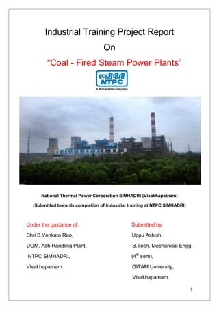
  • 1. 1 Industrial Training Project Report On “Coal - Fired Steam Power Plants” National Thermal Power Corporation SIMHADRI (Visakhapatnam) (Submitted towards completion of industrial training at NTPC SIMHADRI) Under the guidance of: Submitted by: Shri B.Venkata Rao, Uppu Ashish, DGM, Ash Handling Plant, B.Tech, Mechanical Engg. NTPC SIMHADRI, (4th sem), Visakhapatnam. GITAM University, Visakhapatnam.
  • 2. 2 TRAINING SCHEDULE DEPARTMENT PERIOD BOILER MAINTAINANCE 11.05.2015 to 16.05.2015 TURBINE MAINTAINANCE 18.05.2015 to 23.05.2015 OFFSITE MAINTAINANCE 25.05.2015 to 30.05.2015 ASH HANDLING PLANT 01.06.2015 to 09.06.2015
  • 3. 3 CERTIFICATE This is to certify that UPPU ASHISH, a student of 2012-2016 Batch of B.Tech,Mechanical Engineering in 4th Year of GITAM University, Visakhapatnam has successfully completed his industrial training at NTPC Simhadri, Visakhapatnam for four weeks from 7th May to 9th June 2015. He has completed the whole training as per the training report submitted by him. HR Manager NTPC Simhadri, Visakhapatnam
  • 4. 4 Acknowledgment “It is not possible to prepare a project report without the assistance & encouragement of other people. This one is certainly no exception.” On the very outset of this report, I would like to extend my sincere & heartfelt obligation towards all the personages who have helped me in this endeavor. Without their active guidance, help, cooperation & encouragement, I would not have made headway in the industrial training I am ineffably indebted to Mr. K.N. Reddy, AGM (MM-BMD); Mr. D.Shravan, Dy. Manager (BMD-PP); Mr. Piyush Kanwar, Dy. Manager (BMD-Mills); Mr. Balaji, Dy. Manager (BMD-RM); Mr. T.Prem Das, AGM (MM-TMD & OS); Mr. Shridhar, Dy. Manager (MM-TMD) for conscientious and encouragement to accomplish this assignment. I am extremely thankful and pay my gratitude to my guide Mr. B.Venkata Rao for his valuable guidance and support on completion of this project in its presently. I extend my gratitude to NTPC Ltd Simhadri and HR-EDC Dept. of NTPC Ltd Simhadri for giving me this opportunity. I also acknowledge with a deep sense of reverence, my gratitude towards my parents, who has always supported me morally as well as economically. Any omission in this brief acknowledgement does not mean lack of gratitude. Thanking You Ashish Uppu
  • 5. 5 TABLE OF CONTENTS 1. About NTPC……………………………………………… 6 2. About NTPC SIMHADRI……………………………. 14 3. NTPC power stations in India…………………… 18 4.Principal and Operation of a Thermal Power Plant…………………………………………………………. 19 5.Principal components of a 500MW Thermal Power Plant………………………………………………. 29 6.The Layout of NTPC Simhadri……………………. 45 7.Boiler and its auxiliaries……………………………. 48 8.The Steam Turbine Theory……………………… 118 9. Turbine and its auxiliaries……………………… 128 10. DM treatment plant……………………………………………………….. 161 11. Cooling Towers…………………………………. 169 12. Circulating Water System…………………. 174 13. Principal components of CWS………….. 178 14. Ash Handling System……………………….. 183 15. Ways to increase the thermal efficiency of power plants………………………………………….. 187 16. Losses during operation & maintenance of a power plant…………………………………………. 190 5 TABLE OF CONTENTS 1. About NTPC……………………………………………… 6 2. About NTPC SIMHADRI……………………………. 14 3. NTPC power stations in India…………………… 18 4.Principal and Operation of a Thermal Power Plant…………………………………………………………. 19 5.Principal components of a 500MW Thermal Power Plant………………………………………………. 29 6.The Layout of NTPC Simhadri……………………. 45 7.Boiler and its auxiliaries……………………………. 48 8.The Steam Turbine Theory……………………… 118 9. Turbine and its auxiliaries……………………… 128 10. DM treatment plant……………………………………………………….. 161 11. Cooling Towers…………………………………. 169 12. Circulating Water System…………………. 174 13. Principal components of CWS………….. 178 14. Ash Handling System……………………….. 183 15. Ways to increase the thermal efficiency of power plants………………………………………….. 187 16. Losses during operation & maintenance of a power plant…………………………………………. 190 5 TABLE OF CONTENTS 1. About NTPC……………………………………………… 6 2. About NTPC SIMHADRI……………………………. 14 3. NTPC power stations in India…………………… 18 4.Principal and Operation of a Thermal Power Plant…………………………………………………………. 19 5.Principal components of a 500MW Thermal Power Plant………………………………………………. 29 6.The Layout of NTPC Simhadri……………………. 45 7.Boiler and its auxiliaries……………………………. 48 8.The Steam Turbine Theory……………………… 118 9. Turbine and its auxiliaries……………………… 128 10. DM treatment plant……………………………………………………….. 161 11. Cooling Towers…………………………………. 169 12. Circulating Water System…………………. 174 13. Principal components of CWS………….. 178 14. Ash Handling System……………………….. 183 15. Ways to increase the thermal efficiency of power plants………………………………………….. 187 16. Losses during operation & maintenance of a power plant…………………………………………. 190
  • 6. 6 About NTPC NTPC Limited is the largest thermal power generating company of India, Public Sector Company. It was incorporated in the year 1975 to accelerate power development in the country as a wholly owned company of the Government of India. NTPC is emerging as a diversified power major with presence in the entire value chain of the power generation business. Apart from power generation, which is the mainstay of the company, NTPC has already ventured into consultancy, power trading, ash utilization and coal mining. NTPC ranked 341st in the ‘2010, Forbes Global 2000’ ranking of the World’s biggest companies. NTPC became a Maharatna company in May, 2010, one of the only four companies to be awarded this status. Within a span of 31 years, NTPC has emerged as a truly national power company, with power generating facilities in all the major regions of the country. NTPC's core business is engineering, construction and operation of power generating plants and providing consultancy to power utilities in India and abroad. The total installed capacity of the company is 31134 MW (including JVs) with 15coal based and 7 gas based stations, located across the country. In addition under JVs, 3 stations are coal based & another station uses
  • 7. 7 naphtha/LNG as fuel. By 2017, the power generation portfolio is expected to have a diversified fuel mix with coal based capacity of around 53000 MW, 10000 MW through gas, 9000 MW through Hydro generation, about 2000 MW from nuclear sources and around 1000MW from Renewable Energy Sources (RES). NTPC has adopted a multi- pronged growth strategy which includes capacity addition through green field projects, expansion of existing stations, joint ventures, subsidiaries and takeover of stations. NTPC has been operating its plants at high efficiency levels. Although the company has 18.79% of the total national capacity it contributes 28.60% of total power generation due to its focus on high efficiency. NTPC’s share at 31 Mar 2001of the total installed capacity of the country was 24.51% and it generated 29.68%of the power of the country in 2008-09. Every fourth home in India is lit by NTPC.170.88BU of electricity was produced by its stations in the financial year 2005-2006. The Net Profit after Tax on March 31, 2006 was INR 58,202 million. The Net Profit after Tax for the quarter ended June 30, 2006 was INR 15528 million, which is 18.65% more than for the same quarter in the previous financial year. 2005). NTPC is as second best utility in the world. In October 2004, NTPC launched its Initial Public Offering (IPO) consisting of 5.25% as fresh issue and 5.25% as offer for sale by Government of India. NTPC thus became a listed company in November 2004 with the Government holding 89.5% of the equity share capital. In February 2010, the Shareholding of Government of India was reduced from 89.5% to 84.5% through Further Public Offer and the balance 10.5% is held by FIIs, Domestic Banks, Public and others.
  • 8. 8 NTPC Limited Type Public Founded 1975 Headquarters Delhi, India Key people R S Sharma, Chairman & Managing Director Industry Electricity generation Products Electricity Revenue INR 416.37 billion (2008) Net income INR 70.47 billion (2008) Employees 23867 (2006) Website http://www.ntpc.co.in 8 NTPC Limited Type Public Founded 1975 Headquarters Delhi, India Key people R S Sharma, Chairman & Managing Director Industry Electricity generation Products Electricity Revenue INR 416.37 billion (2008) Net income INR 70.47 billion (2008) Employees 23867 (2006) Website http://www.ntpc.co.in 8 NTPC Limited Type Public Founded 1975 Headquarters Delhi, India Key people R S Sharma, Chairman & Managing Director Industry Electricity generation Products Electricity Revenue INR 416.37 billion (2008) Net income INR 70.47 billion (2008) Employees 23867 (2006) Website http://www.ntpc.co.in
  • 9. 9 Strategies of NTPC Technological Initiatives  Introduction of steam generators (boilers) of the size of 800 MW.  Integrated Gasification Combined Cycle (IGCC) Technology.  Launch of Energy Technology Centre -A new initiative for development of technologies with focus on fundamental R&D.  The company sets aside up to 0.5% of the profits for R&D.  Roadmap developed for adopting μClean Development.  Mechanism to help get / earn μCertified Emission Reduction.
  • 10. 10 Corporate Social Responsibility  As a responsible corporate citizen NTPC has taken up number of CSR initiatives.  NTPC Foundation formed to address Social issues at national level  NTPC has framed Corporate Social Responsibility Guidelines committing up to 0.5% of net profit annually for Community Welfare.  The welfare of project affected persons and the local population around NTPC projects are taken care of through well drawn Rehabilitation and Resettlement policies.  The company has also taken up distributed generation for remote rural areas Partnering government in various initiatives  Consultant role to modernize and improvise several plants across the country.  Disseminate technologies to other players in the sector.  Consultant role Partnership in Excellence Programme for improvement of PLF of 15 Power Stations of SEBs.  Rural Electrification work under Rajiv Gandhi Garmin Vidyutikaran. Environment management  All stations of NTPC are ISO 14001 certified.  Various groups to care of environmental issues.  The Environment Management Group.  Ash tilization Division.  Afforestation Group.  Centre for Power Efficiency & Environment Protection.  Group on Clean Development Mechanism.
  • 11. 11  NTPC is the second largest owner of trees in the country after the Forest department. Vision “To be the world’s largest and best power producer, powering India’s growth.” Mission “Develop and provide reliable power, related products and services at competitive prices, integrating multiple energy sources with innovative and eco-friendly technologies and contribute to society.” Core Values – BE COMMITTED B Business ethics E Environmentally and Economically Sustainable C Customer Focus O Organizational and Professional Pride M Mutual Respect and Trust M Motivating Self and Others I Innovation and Speed T Total Quality for Excellence T Transparent and Respected Organization E Enterprising D Devoted
  • 12. 12 Journey of NTPC 12 Journey of NTPC 12 Journey of NTPC
  • 13. 13 A Qualitative study of the Company
  • 14. 14 About NTPC Simhadri Simhadri Super Thermal Power Plant is a coal-fired power plant located in the Visakhapatnam district of the Indian state of Andhra Pradesh. The power plant is one of the coal fired power plants of NTPC, a Government of India enterprise. The coal for the power plant is sourced from Kalinga Block of Talcher Coal fields in Odisha. Power generated by units 1 and 2, making up for 1,000 MW, is dedicated to power distribution companies owned by the Government of Andhra Pradesh. The remainder 1,000 MW, generated by units 3 and 4, is allocated to the states of Odisha, Tamil Nadu, and Karnataka. Their shares are decided arbitrarily, with unsold power being sold to Andhra Pradesh. NTPC Simhadri is a modern coal-fired power plant, and is a combination of four independent generation units, with common water and fuel sources, and common ash ponds. Each of the four units has a nameplate capacity of 500 MW. Units 1 and 2 were built in the first phase of development, and were commissioned in February 2002 and
  • 15. 15 August 2004, respectively, to meet urgent needs of power in the largely agrarian Coastal Andhra and North-Coastal Andhra regions. Units 3 and 4 were built in the second phase, and commissioned in March 2011 and March 2012, respectively. Since the operator of this plant is a Government of India enterprise, and since the plant was built with central government funds, power generated by units 3 and 4 are sold to distribution companies based in neighboring states of Odisha, Tamil Nadu, and Karnataka, over the National Grid, as power stocks. The allocations are decided between NTPC and the three states' discoms. Unsold units are offered to discoms of Andhra Pradesh for purchase at market prices. Coal for NTPC Simhadri is sourced from Talcher Coal Fields, Odisha, and transported by East Coast Railway (ECoR), over the Kolkata- Chennai trunk line, with a spur heading towards the plant at Duvvada. NTPC Simhadri uses fresh water sourced from the Yeluru Canal as working fluid (steam which turns the turbines). For cooling, however, the plant uses seawater pumped in from the Bay of Bengal. Seawater, with its salt content, is unfit to be used as working fluid, without desalination.
  • 16. 16 PROJECT PROFILE Approved Capacity 2000 MW (4 X 500 MW) Location Paravada Mandal, Visakhapatnam, AP Source of Finance JBIC Loan and Internal Resources Fuel Source Mahanadi Coal Fields, Talcher Fuel Requirement 5.04 Million Tons of Coal per annum Mode of Transportation Rail DM Water Source Water from Yelluru Canal Sweet Water Requirement 600 m3 / hr Cooling Water Source Sea Water from Bay of Bengal Sea Water Requirement 9100 m3 / hr Main Contractor M/s BHEL Power Evacuation AP TRANSCO (Via Kalpaka) Beneficiary State Andhra Pradesh 16 PROJECT PROFILE Approved Capacity 2000 MW (4 X 500 MW) Location Paravada Mandal, Visakhapatnam, AP Source of Finance JBIC Loan and Internal Resources Fuel Source Mahanadi Coal Fields, Talcher Fuel Requirement 5.04 Million Tons of Coal per annum Mode of Transportation Rail DM Water Source Water from Yelluru Canal Sweet Water Requirement 600 m3 / hr Cooling Water Source Sea Water from Bay of Bengal Sea Water Requirement 9100 m3 / hr Main Contractor M/s BHEL Power Evacuation AP TRANSCO (Via Kalpaka) Beneficiary State Andhra Pradesh 16 PROJECT PROFILE Approved Capacity 2000 MW (4 X 500 MW) Location Paravada Mandal, Visakhapatnam, AP Source of Finance JBIC Loan and Internal Resources Fuel Source Mahanadi Coal Fields, Talcher Fuel Requirement 5.04 Million Tons of Coal per annum Mode of Transportation Rail DM Water Source Water from Yelluru Canal Sweet Water Requirement 600 m3 / hr Cooling Water Source Sea Water from Bay of Bengal Sea Water Requirement 9100 m3 / hr Main Contractor M/s BHEL Power Evacuation AP TRANSCO (Via Kalpaka) Beneficiary State Andhra Pradesh
  • 17. 17 Salient Features of NTPC Simhadri • First Coastal Based Coal fired thermal Power Project of NTPC • Biggest Sea Water Intake-Well in India (For Drawing Sea Water from Bay of Bengal) • Use of Sea Water for Condenser Cooling and Ash Disposal • Asia’s Tallest Natural Cooling Towers (165 m), 6th in the World • Use of Fly-Ash Bricks in the Construction of all Buildings • Coal Based Project of NTPC Whose Entire Power is allocated to Home State (AP) • Use of Monitors and Large Video Screens (LVS) as Man Machine Interface (MMIs) for Operating the Plant • Use of Process Analysis, Diagnosis and Optimization (PADO) for the first time in NTPC • Flame Analysis of Boiler by Dedicated Scanners for all Coal Burners • Boiler Mapping By Acoustic Pyrometers • Use of Distributed Digital Control and Management Information System (DDCMIS) • Totally Spring Loaded Floating Foundation for all Major Equipments Including TG • Use of INERGEN as Fire Protection System for the 1st time in NTPC • Use of Digital Automatic Voltage Regulator (DAVR) • Use of VFD in ID Fan
  • 18. 18 NTPC POWER STATIONS IN INDIA 18 NTPC POWER STATIONS IN INDIA 18 NTPC POWER STATIONS IN INDIA
  • 19. 19 Principle and Operation of a Thermal Power Plant Principle: Any Steam Power Plant operates under the Simple Rankine Cycle. Hence the Rankine cycle is often termed as Basic Power Plant Cycle. The Rankine Cycle The Rankine cycle is a thermodynamic cyclewhich converts heat into work. The heat is supplied externally to a closed loop, which usually uses water as the working fluid. This cycle generates about 80% of all electric power used throughout the world, including virtually all solar, thermal, biomass, coal and nuclear power plants. It is named after William John Macquorn Rankine,aScottish polymath. The thermal (steam) power plant uses a dual (vapour+liquid) phase cycle. It is a closed cycle to enable the working fluid (water) to be used again and again. The basic principle of the working of a Thermal Power Plant is quite simple. The fuel used in the plant is burnt in the boiler, and the heat generated is then used to boil water which is circulated through several Layout of a Simple Rankine Cycle T-S diagram of a Simple Rankine Cycle 19 Principle and Operation of a Thermal Power Plant Principle: Any Steam Power Plant operates under the Simple Rankine Cycle. Hence the Rankine cycle is often termed as Basic Power Plant Cycle. The Rankine Cycle The Rankine cycle is a thermodynamic cyclewhich converts heat into work. The heat is supplied externally to a closed loop, which usually uses water as the working fluid. This cycle generates about 80% of all electric power used throughout the world, including virtually all solar, thermal, biomass, coal and nuclear power plants. It is named after William John Macquorn Rankine,aScottish polymath. The thermal (steam) power plant uses a dual (vapour+liquid) phase cycle. It is a closed cycle to enable the working fluid (water) to be used again and again. The basic principle of the working of a Thermal Power Plant is quite simple. The fuel used in the plant is burnt in the boiler, and the heat generated is then used to boil water which is circulated through several Layout of a Simple Rankine Cycle T-S diagram of a Simple Rankine Cycle 19 Principle and Operation of a Thermal Power Plant Principle: Any Steam Power Plant operates under the Simple Rankine Cycle. Hence the Rankine cycle is often termed as Basic Power Plant Cycle. The Rankine Cycle The Rankine cycle is a thermodynamic cyclewhich converts heat into work. The heat is supplied externally to a closed loop, which usually uses water as the working fluid. This cycle generates about 80% of all electric power used throughout the world, including virtually all solar, thermal, biomass, coal and nuclear power plants. It is named after William John Macquorn Rankine,aScottish polymath. The thermal (steam) power plant uses a dual (vapour+liquid) phase cycle. It is a closed cycle to enable the working fluid (water) to be used again and again. The basic principle of the working of a Thermal Power Plant is quite simple. The fuel used in the plant is burnt in the boiler, and the heat generated is then used to boil water which is circulated through several Layout of a Simple Rankine Cycle T-S diagram of a Simple Rankine Cycle
  • 20. 20 tubes, the steam that is generated is used to drive a turbine, which in turn is coupled with a generator, which then produces the electricity. A Rankine cycle describes a model of the operation of steam heat engines most commonly found in power generation plants. Common heat sources for power plants using the Rankine cycle are coal, natural gas, oil, and nuclear. The Rankine cycle is sometimes referred to as a practical Carnot cycle as, when an efficient turbine is used, the TS diagram will begin to resemble the Carnot cycle. The main difference is that a pump is used to pressurize liquid instead of a gas. This requires about 1/100th (1%) as much energy as that compressing a gas in a compressor (as in the Carnot cycle).The efficiency of a Rankine cycle is usually limited by the working fluid. Without the pressure going super critical the temperature range the cycle can operate over is quite small, turbine entry temperatures are typically 565°C (the creep limit of stainless steel) and condenser temperatures are around 30°C. This gives a theoretical Carnot efficiency of around 63% compared with an actual efficiency of 42% for a modern coal-fired power station. This low turbine entry temperature (compared with a gas turbine) is why the Rankine cycle is often used as a bottoming cycle in combined cycle gas turbine power stations. The working fluid in a Rankine cycle follows a closed loop and is re-used constantly. The water vapor and entrained droplets often seen billowing from power stations is generated by the cooling systems (not from the closed loop Rankine power cycle) and represents the waste heat that could not be converted to useful work. Note that cooling towers operate using the latent heat of vaporization of the cooling fluid. The white billowing clouds that form in cooling tower operation are the result of water droplets which are entrained in the cooling tower airflow; it is not, as commonly thought, steam. While many substances could be used in the Rankine cycle, water is usually the fluid
  • 21. 21 of choice due to its favorable properties, such as nontoxic and un reactive chemistry, abundance, and low cost, as well as its thermodynamic properties. One of the principal advantages it holds over other cycles is that during the compression stage relatively little work is required to drive the pump, due to the working fluid being in its liquid phase at this point. By condensing the fluid to liquid, the work required by the pump will only consume approximately 1% to 3% of the turbine power and so give a much higher efficiency for a real cycle. The benefit of this is lost somewhat due to the lower heat addition temperature. Gas turbines, for instance, have turbine entry temperatures approaching 1500°C. Nonetheless, the efficiencies of steam cycles and gas turbines are fairly well matched. Ts diagram of a typical Rankine cycle operating between pressures of 0.06bar and 50bar. There are four processes in the Rankine cycle, each changing the state of the working fluid. These states are identified by number in the diagram to the right T-S diagram of a Typical Rankine cycle 21 of choice due to its favorable properties, such as nontoxic and un reactive chemistry, abundance, and low cost, as well as its thermodynamic properties. One of the principal advantages it holds over other cycles is that during the compression stage relatively little work is required to drive the pump, due to the working fluid being in its liquid phase at this point. By condensing the fluid to liquid, the work required by the pump will only consume approximately 1% to 3% of the turbine power and so give a much higher efficiency for a real cycle. The benefit of this is lost somewhat due to the lower heat addition temperature. Gas turbines, for instance, have turbine entry temperatures approaching 1500°C. Nonetheless, the efficiencies of steam cycles and gas turbines are fairly well matched. Ts diagram of a typical Rankine cycle operating between pressures of 0.06bar and 50bar. There are four processes in the Rankine cycle, each changing the state of the working fluid. These states are identified by number in the diagram to the right T-S diagram of a Typical Rankine cycle 21 of choice due to its favorable properties, such as nontoxic and un reactive chemistry, abundance, and low cost, as well as its thermodynamic properties. One of the principal advantages it holds over other cycles is that during the compression stage relatively little work is required to drive the pump, due to the working fluid being in its liquid phase at this point. By condensing the fluid to liquid, the work required by the pump will only consume approximately 1% to 3% of the turbine power and so give a much higher efficiency for a real cycle. The benefit of this is lost somewhat due to the lower heat addition temperature. Gas turbines, for instance, have turbine entry temperatures approaching 1500°C. Nonetheless, the efficiencies of steam cycles and gas turbines are fairly well matched. Ts diagram of a typical Rankine cycle operating between pressures of 0.06bar and 50bar. There are four processes in the Rankine cycle, each changing the state of the working fluid. These states are identified by number in the diagram to the right T-S diagram of a Typical Rankine cycle
  • 22. 22 I. Process 1-2: The working fluid is pumped from low to high pressure, as the fluid is a liquid at this stage the pump requires little input energy. II. Process 2-3: The high pressure liquid enters a boiler where it is heated at constant pressure by an external heat source to become a dry saturated vapor. III. Process 3-4: The dry saturated vapor expands through a turbine, generating power. This decreases the temperature and pressure of the vapor and some condensation may occur. IV. Process 4-1: The wet vapor then enters a condenser where it is condensed at a constant pressure and temperature to become a saturated liquid. The pressure and temperature of the condenser is fixed by the temperature of the cooling coils as the fluid is undergoing a phase-change. In an ideal Rankine cycle thepumpand turbine would be isentropic, i.e., the pump and turbine would generate no entropy and hence maximize the net work output processes1-2and 3-4 would be represented by vertical lines onthe Ts diagram. The Rankine cycle shown here prevents the vapor ending up in the superheat region after the expansion in the turbine, which reduces the energy removed by the condensers. In a real Rankine cycle, the compression by the pump and the expansion in the turbine are not isentropic. In other words, these processes are non-reversible and entropy is increased during the two processes. This somewhat increases the power required by the pump and decreases the power generated by the turbine. In particular the efficiency of the steam turbine will be limited by water droplet formation. As thewater condenses, water droplets hit the turbine blades at high speed causing pitting and erosion, gradually decreasing the life of turbine
  • 23. 23 blades and efficiency of the turbine. The easiest way to overcome this problem is by superheating the steam. On the Ts diagram above, state 3 is above a two phase region of steam and water so after expansion the steam will be very wet. By superheating, state 3 will move to the right of the diagram and hence produce a dryer steam after expansion. Rankine Cycle with Reheat In this two turbines work in series on a common shaft. The first accepts vapor from the boiler at a high pressure. After the vapor has passed through the first turbine (also referred as H.P turbine), it renters the boiler and is reheated before it is allowed to pass through the second turbine (often referred to as L.P turbine).It prevents the vapor from condensing during its expansion which can intensely damage the turbine blades, and improves the efficiency of the cycle by decreasing the net work output. To protect the reheat tubes, steam is not allowed to expand Rankine Cycle with superheating
  • 24. 24 deep into the two-phase region before it is taken for reheating, because in that case the moisture particles in the steam while evaporating would leave behind solid deposits in the form of scale which is difficult to remove. A low reheat pressure may bring down the cycle efficiency. Again, a high reheat pressure increases the moisture content at turbine exhaust. Thus the reheat pressure is optimized. By increasing the number of reheats, still higher steam pressures could be used, but mechanical stresses increase at a higher proportion then the increase in pressure, also increase. Hence more than two reheats have not been used so far. Regenerative Rankine Cycle The main aim of the Regenerative Rankine cycle is to improve the cycle efficiency by decreasing the net heat input. In Regenerative Rankine cycle, after emerging from the condenser (possibly as a sub cooled liquid) the working fluid is heated by steam tapped from the hot portion of the cycle (i.e. from the intermediate stages of the turbine). On the Rankine Cycle with Reheat
  • 25. 25 diagram shown, the fluid at 2 is mixed with the fluid at 4 (both at the same pressure) to end up with a saturated liquid at 7. Reheat-Regenerative Cycle The reheating of steam is adopted when the vaporization pressure is high. The effect of reheat alone on the thermal efficiency of the cycle is very small. Regeneration or the heating up of feed water by steam extracted from the turbine has a marked effect on cycle efficiency. The Reheat-Regenerative Rankine cycle (with minor variants) is commonly used in modern steam power stations. Another variation is where 'bleed steam' from between turbine stages is sent to feed water heaters to preheat thewateronits way from the condenser to the boiler. Regenerative Rankine Cycle
  • 26. 26 Factors affecting thermal cycle efficiency 1. Initial steam pressure 2. Initial steam temperature 3. Reheat pressure and temperature, if reheat is used 4. Condenser pressure 5. Regenerative feed water heating Operation-Fundamentals of Coal to Electricity: Reheat – Regenerative Rankine Cycle Operation of a Steam Power Plant 26 Factors affecting thermal cycle efficiency 1. Initial steam pressure 2. Initial steam temperature 3. Reheat pressure and temperature, if reheat is used 4. Condenser pressure 5. Regenerative feed water heating Operation-Fundamentals of Coal to Electricity: Reheat – Regenerative Rankine Cycle Operation of a Steam Power Plant 26 Factors affecting thermal cycle efficiency 1. Initial steam pressure 2. Initial steam temperature 3. Reheat pressure and temperature, if reheat is used 4. Condenser pressure 5. Regenerative feed water heating Operation-Fundamentals of Coal to Electricity: Reheat – Regenerative Rankine Cycle Operation of a Steam Power Plant
  • 27. 27
  • 28. 28 MM Mechanical Power to Electric Power As the blades of the turbine rotate, the shaft of the generator which is coupled to that of the turbine also rotates .It causes rotation of the exciter which produces an induced emf (electric power)
  • 29. 29 Principle components of a 500MW thermal power plant Any 500MW thermal power plant comprises of the following components: 1. Cooling tower 2. Cooling water pump 3. Transmission line (3-phase) 4. Unit transformer (3-phase) 5. Electric generator (3-phase) 6. Low pressure turbine 7. Feed Water Pump A typical 500MW Thermal Power Plant 29 Principle components of a 500MW thermal power plant Any 500MW thermal power plant comprises of the following components: 1. Cooling tower 2. Cooling water pump 3. Transmission line (3-phase) 4. Unit transformer (3-phase) 5. Electric generator (3-phase) 6. Low pressure turbine 7. Feed Water Pump A typical 500MW Thermal Power Plant 29 Principle components of a 500MW thermal power plant Any 500MW thermal power plant comprises of the following components: 1. Cooling tower 2. Cooling water pump 3. Transmission line (3-phase) 4. Unit transformer (3-phase) 5. Electric generator (3-phase) 6. Low pressure turbine 7. Feed Water Pump A typical 500MW Thermal Power Plant
  • 30. 30 8. Condenser 9. Intermediate pressure turbine 10. Steam governor valve 11. High pressure turbine 12. Deaerator 13. Feed heater 14. Coal conveyor 15. Coal hopper 16. Pulverized coal mill 17. Boiler drum 18. Ash hopper 19. Super heater 20. Forced draught fan 21. Re heater 22. Air intake tower 23. Economizer 24. Air pre heater 25. Electrostatic Precipitator (ESP) 26. Induced draught fan 27. Flue Gas 1. Cooling Tower Cooling towers are heat removal devices used to transfer process waste heat to the atmosphere. Cooling towers may either use the evaporation of water to remove process heat and cool the working fluid to near the wet-bulb air temperature or in the case of closed circuit dry cooling towers rely solely on air to cool the working fluid to near the dry-bulb air temperature. However, evaporative type cooling
  • 31. 31 towers are most commonly used. Common applications include cooling the circulating water used in oil refineries, chemical plants, power stations and building cooling. The towers vary in size from small roof-top units to very large hyperboloid structures that can be up to 200 meters tall and 100 meters in diameter, or rectangular structures that can be over 40 meters tall and 80 meters long. Smaller towers are normally factory-built, while larger ones are constructed on site. The absorbed heat is rejected to the atmosphere by the evaporation of some of the cooling water in mechanical forced-draft or induced Draft towers or in natural draft hyperbolic shaped cooling towers as seen at most nuclear power plants. 2. Cooling Water Pump It pumps the water from the cooling tower to the condenser. 3. Three Phase Transmission line Three phase electric power is a common method of electric power transmission. It is a type of polyphase system mainly used to power motors and many other devices. A three phase system uses less conductive material to transmit electric power than equivalent single phase, two phase, or direct current system at the same voltage. In a three phase system, three circuits reach their instantaneous peak values at different times. Taking current in one conductor as the reference, the currents in the other two are delayed in time by one- third and two-third of one cycle .This delay between “phases” has the effect of giving constant power transfer over each cycle of the current and also makes it possible to produce a rotating magnetic field in an electric motor. At the power station, an electric generator converts mechanical power into a set of electric currents, one from each
  • 32. 32 electromagnetic coil or winding of the generator. The current are sinusoidal functions of time, all at the same frequency but offset in time to give different phases. In a three phase system the phases are spaced equally, giving a phase separation of one-third of one cycle. Generators output at a voltage that ranges from hundreds of volts to 30,000 volts. 4. Unit transformer (3-phase) At the power station, transformers step-up this voltage to one more suitable for transmission. After numerous further conversions in the transmission and distribution network the power is finally transformed to the standard mains voltage (i.e. the “household” voltage). The power may already have been split into single phase at this point or it may still be three phase. Where the step-down is three phase at the receiving stage, the output of this transformer is usually star connected with the standard mains voltage being the phase-neutral voltage. Another system commonly seen in North America is to have a delta connected secondary with a center tap on one of the windings supplying the ground and neutral. This allows for 240 V three phase as well as three different single phase voltages( 120 V between two of the phases and neutral , 208 V between the third phase ( or wild leg) and neutral and 240 V between any two phase) to be available from the same supply. A unit Transformer
  • 33. 33 5. Electrical generator An Electrical generator is a device that converts kinetic energy to electrical energy, generally using electromagnetic induction. The task of converting the electrical energy into mechanical energy is accomplished by using a motor. The source of mechanical energy maybe water falling through the turbine or steam turning a turbine (as is the case with thermal power plants). There are several classifications for modern steam turbines. Steam turbines are used in our entire major coal fired power stations to drive the generators or alternators, which produce electricity. The turbines themselves are driven by steam generated in "boilers “or "steam generators" as they are sometimes called. Electrical power stations use large steam turbines driving electric generators to produce most (about 86%) of the world’s electricity. These centralized stations are of two types: fossil fuel power plants and nuclear power plants. The turbines used for electric power generation are most often directly coupled to their- generators .As the generators must rotate at constant synchronous speeds according to the frequency of the electric power system, the most common speeds are 3000 r/min for 50 Hz systems, and 3600 r/min for 60 Hz systems. Most large nuclear sets rotate at half those speeds, and have a 4-pole generator rather than the more common 2-pole one. An electric generator with an excitor
  • 34. 34 6. Low Pressure Turbine Energy in the steam after it leaves the boiler is converted into rotational energy as it passes through the turbine. The turbine normally consists of several stages with each stages consisting of a stationary blade (or nozzle) and a rotating blade. Stationary blades convert the potential energy of the steam into kinetic energy and direct the flow onto the rotating blades. The rotating blades convert the kinetic energy into impulse and reaction forces, caused by pressure drop, which results in the rotation of the turbine shaft. The turbine shaft is connected to a generator, which produces the electrical energy. Low Pressure Turbine (LPT) consists of 2x6 stages. After passing through Intermediate Pressure Turbine steam is passed through LPT which is made up of two parts- LPC REAR & LPC FRONT. As water gets cooler here it gathers into a HOTWELL placed in lower parts of turbine. 7. Feed Water Pump A Boiler feed water pump or simply a feed water pump is a specific type of pump used to pump water into a steam boiler. The water may be freshly supplied or returning condensation of the steam produced by the boiler. These pumps are normally high pressure units that use suction from a condensate return system and can be of the centrifugal pump type or positive displacement type. Feed water pumps range in size up to many horsepower and the electric motor is usually separated from the pump body by some form of mechanical coupling. Large industrial condensate pumps may also serve as the feed water pump. In either case, to force the water into the boiler, the pump must generate sufficient pressure to overcome the steam pressure developed by the boiler. This is usually accomplished
  • 35. 35 through the use of a centrifugal pump. Feed water pumps usually run intermittently and are controlled by a float switch or other similar level-sensing device energizing the pump when it detects a lowered liquid level in the boiler. Some pumps contain a two-stage switch. As liquid lowers to the trigger point of the first stage, the pump is activated. If the liquid continues to drop, (perhaps because the pump has failed, its supply has been cut off or exhausted, or its discharge is blocked) the second stage will be triggered. This stage may switch off the boiler equipment (preventing the boiler from running dry and overheating); trigger an alarm, or both. 8. Condenser The steam coming out from the Low Pressure Turbine (a little above its boiling pump) is brought into thermal contact with cold water (pumped in from the cooling tower) in the condenser, where it condenses rapidly back into water, creating near Vacuum-like conditions inside the condenser chest allowing it to be pumped. If the condenser can be made cooler, the pressure of the exhaust steam is reduced and efficiency of the cycle increases. The surface condenser is a shell and tube heat exchanger in which cooling water is circulated through the tubes. The exhaust steam from the low pressure turbine enters the shell where it is cooled and converted to condensate (water) by flowing over the tubes as shown in the adjacent diagram. Such condensers use steam ejectors or rotary motor-driven exhausters for continuous removal of air and gases from the steam side to maintain vacuum.
  • 36. 36 9. Intermediate Pressure Turbine Intermediate Pressure Turbine (IPT) consists of 12 stages. When the steam has been passed through HPT it enters into IPT. IPT has two ends named as FRONT & REAR. Steam enters through front end and leaves from Rear end. 10. Steam Governor Valve Steam locomotives and the steam engines used on ships and stationary applications such as power plants also required feed water pumps. In this situation, though, the pump was often powered using a small steam engine that ran using the steam produced by the boiler a means had to be provided, of course, to put the initial charge of water into the boiler (before steam power was available to operate the steam-powered feed water pump).The pump was often a positive displacement pump that had steam valves and cylinders at one end and feed water cylinders at the other end; no crankshaft was required. In thermal plants, the primary purpose of surface condenser is to condense the exhaust steam from a steam turbine to obtain maximum efficiency and also to convert the turbine exhaust steam into pure water so that it may be reused in the steam generator or boiler as boiler feed water. By condensing the exhaust steam of a turbine at a pressure below atmospheric pressure, the steam pressure drop between the inlet and exhaust of the turbine is increased, which increases the amount heat available for conversion to mechanical power. Most of the heat liberated due to condensation of the exhaust steam is carried away by the cooling medium (water or air) used by the surface condenser. Control valves are valves used within industrial plants and elsewhere to control operating
  • 37. 37 conditions such as temperature, pressure, flow and liquid level by fully or partially opening or closing in response to signals received from controllers that compares a “set point” to a “process variable” whose value is provided by sensors that monitor changes in such conditions. The opening or closing of control valves is done by means of electrical, hydraulic or pneumatic systems. 11. High Pressure Turbine Steam coming from Boiler directly feeds into HPT at a temperature of 540°C and at a pressure of 170 kg/cm2. Here it passes through 12 different stages due to which its temperature goes down to 350°C and pressure as 45 kg/cm2. This line is also called as CRH – COLD REHEAT LINE. It is now passed to a REHEATER where its temperature rises to 540°C and called as HRH-HOT REHEATED LINE. 12. Deaerator A Deaerator is a boiler feed device for air removal and used to remove dissolved gases (an alternate would be the use of water treatment chemicals) from boiler feed water to make it noncorrosive. A deaerator is an open type feed water heater. A dearator typically includes a vertical domed deaeration section as the deaeration boiler feed water tank. A steam generating boiler requires that the circulating steam, condensate, and feed water should be devoid of dissolved gases, particularly corrosive ones and dissolved or suspended solids. The gases will give rise to corrosion of the metal. The solids will deposit on the heating surfaces giving rise to localized heating and tube ruptures due to overheating. Under some conditions it may give rise to stress corrosion cracking. Deaerator
  • 38. 38 level and pressure must be controlled by adjusting control valves the level by regulating condensate flow and the pressure by regulating steam flow. If operated properly, most deaerators will guarantee that oxygen in the deaerated water will not exceed 7 ppb by weight (0.005 cm3/L). 13. Feed water heater A Feed water heater is a power plant component used to pre-heat water delivered to a steam generating boiler. Preheating the feed water reduces the irreversibility involved in steam generation and therefore improves the thermodynamic efficiency of the system. This reduces plant operating costs and also helps to avoid thermal shock to the boiler metal when the feed water is introduced back into the steam cycle. In a steam power (usually modeled as a modified Rankine cycle), feed water heaters allow the feed water to be brought up to the saturation temperature very gradually. This minimizes the inevitable irreversibility associated with heat transfer to the working fluid (water). 14. Coal conveyor Coal conveyors are belts which are used to transfer coal from its storage place to Coal Hopper. A belt conveyor consists of two pulleys, with a continuous loop of material- the conveyor Belt – that rotates about them. The pulleys are powered, moving the belt and the material on the belt forward. Conveyor belts are extensively used to transport industrial and agricultural material, such as grain, coal, ores etc.
  • 39. 39 15. Coal Hopper Coal Hoppers are the places which are used to feed coal to Coal Mill. It also has the arrangement of entering Hot Air at 200°C inside it which solves our two purposes: 1. If our Coal has moisture content then it dries it so that a proper combustion takes place. 2. It raises the temperature of coal so that its temperature is more near to its Ignite Temperature so that combustion is easy. 16. Pulverized Coal Mill A pulverizer is a mechanical device for grinding coal for combustion in a furnace in a Thermal power plant. 17. Boiler drum Steam Drums are a regular feature of water tube boilers. It is reservoir of water/steam at the top end of the water tubes in the water-tube boiler. They store the steam generated in the water tubes and act as a phase separator for the steam/water mixture. Usually, the boiler drum is at an elevation of 75m. The difference in densities between hot and cold water helps in the accumulation of the “hotter”- water/and saturated –steam into steam drum. Made from high-grade steel (probably stainless) and its working involve temperature of 390°C and pressure well above 350psi (2.4MPa). The separated steam is drawn out from the top section of the drum. Saturated Steam is drawn off the top of the drum. The steam will re-enter the furnace in through a super heater, while the saturated water at the bottom of steam drum flows down to the mud-drum /feed water drum by down comer tubes accessories include a safety valve, water level
  • 40. 40 indicator and fuse plug. A steam drum is used in company of a mud- drum/feed water drum which is located at a lower level. So that it acts as a sump for the sludge or sediments which have a higher tendency at the bottom. 18. Ash Hopper A steam drum is used in the company of a mud-drum/feed water drum which is located at a lower level. So that it acts as a sump for the sludge or sediments which have a tendency to accumulate at the bottom. 19. Super Heater A Super heater is a device in a steam engine that heats the steam generated by the boiler again increasing its thermal energy. Super heaters increase the efficiency of the steam engine, and were widely adopted. Steam which has been superheated is logically known as superheated steam; non- superheated steam is called saturated steam or wet steam. Super heaters are being applied most stationary steam engines including power stations. The dry steam coming out of the boiler drum passes through three stages of superheating. Initially the main steam is passed through a low temperature super heater followed by a divisional panel super heater and finally through a platen super heater. The resulting steam obtained will be at 540o C this is sent to the inlet of the HP turbine. 20. Force Draught Fan External fans are provided to give sufficient air for combustion. The forced draught fan takes air from the atmosphere and, warms it in the
  • 41. 41 air pre heater for better combustion, injects it via the air nozzles on the furnace wall. 21. Re heater Re heater is a heater which is used to raise the temperature of steam which has exhausted from the high pressure turbine. The steam entering the re heater is known as Cold Reheat (CR). The steam leaving the re heater is known as Hot Reheat (HR). 22. Air Intake Air is taken from the environment by an air intake tower which is fed to the fuel. 23. Economizer Economizers are mechanical devices intended to reduce energy consumption, or to perform another useful function like preheating a fluid. The term economizer is used for other purposes as well-Boiler, power plant, heating, ventilating and air-conditioning. In boilers, economizer are heat exchange devices that heat fluids , usually water, up to but not normally beyond the boiling point of the fluid. Economizers are so named because they can make use of the enthalpy and improving the boiler’s efficiency. They are devices fitted to a boiler which save energy by using the heat from the exhaust gases from the boiler to preheat the cold water used to fill it (the feed water). Modern day boilers, such as those in cold fired power stations, are still fitted with economizer which is decedents of Green’s original design. In this context there are turbines before it is pumped to the boilers. A common application of economizer in steam power plants is to capture the waste heat from boiler stack gases
  • 42. 42 (flue gas) and transfer thus it to the boiler feed water thus lowering the needed energy input , in turn reducing the firing rates to accomplish the rated boiler output . Economizer lower stack temperatures which may cause condensation of acidic combustion gases and serious equipment corrosion damage if care is not taken in their design and material selection. 24. Air Pre heater Air pre heater is a general term to describe any device designed to heat air before another process (for example, combustion in a boiler). The purpose of the air pre heater is to recover the heat from the boiler flue gas which increases the thermal efficiency of the boiler by reducing the useful heat lost in the flue gas. As a consequence, the flue gases are also sent to the flue gas stack (or chimney) at a lower temperature allowing simplified design of the ducting and the flue gas stack. It also allows control over the temperature of gases leaving the stack (chimney). 25. Electrostatic Precipitator (ESP) An Electrostatic precipitator (ESP) or electrostatic air cleaner is a particulate device that removes particles from a flowing gas (such as air) using the force of an induced electrostatic charge. Electrostatic precipitators are highly efficient filtration devices, and can easily remove fine particulate matter such as dust and smoke from the air steam. ESPs continue to be excellent devices for control of many industrial particulate emissions, including smoke from electricity- generating utilities (coal and oil fired), salt cake collection from black liquor boilers in pump mills, and catalyst collection from fluidized bed catalytic crackers from several hundred thousand ACFM in the
  • 43. 43 largest coal-fired boiler applications. The original parallel plate- Weighted wire design (described above) has evolved as more efficient (and robust) discharge electrode designs, today focus is on rigid discharge electrodes to which many sharpened spikes are attached , maximizing corona production. Transformer –rectifier systems apply voltages of 50-100 Kilovolts at relatively high current densities. Modern controls minimize sparking and prevent arcing, avoiding damage to the components. Automatic rapping systems and hopper evacuation systems remove the collected particulate matter while on line allowing ESPs to stay in operation for years at a time. 26. Induced Draught Fan The induced draft fan assists the FD fan by drawing out combustible gases from the furnace, maintaining a slightly negative pressure in the furnace to avoid backfiring through any opening. At the furnace outlet and before the furnace gases are handled by the ID fan, fine dust carried by the outlet gases is removed to avoid atmospheric pollution. This is an environmental limitation prescribed by law, which additionally minimizes erosion of the ID fan. 27. Flue gas stack A Flue gas stack is a type of chimney, a vertical pipe, channel or similar structure through which combustion product gases called flue gases are exhausted to the outside air. Flue gases are produced when coal, oil, natural gas, wood or any other large combustion device. Flue gas is usually composed of carbon dioxide (CO2) and water vapor as well as nitrogen and excess oxygen remaining from the intake combustion air. It also contains a small percentage of pollutants such as particulates matter, carbon mono oxide, nitrogen
  • 44. 44 oxides and sulphur oxides. The flue gas stacks are often quite tall, up to 400 meters (1300 feet) or more, so as to disperse the exhaust pollutants over a greater area and thereby reduce the concentration of the pollutants to the levels required by government's environmental policies and regulations.
  • 45. 45 The Layout of NTPC Simhadri The plant consists of two stages: Stage 1 (consisting of unit 1 and unit 2) and Stage 2 (consisting of unit 3 and unit 4).Each unit has an average capacity of 500MW.The boilers used in all the units are sub critical type and employ tilting tangential firing. Each unit of stage 1 comprises of nine coal mills (bowl mills) while each unit of stage 2 consists of ten coal mills. In addition to, an HP turbine and an LP turbine the plant uses an IP turbine too. Each pressure part in a unit employs three pumps out of which one is a standby and two are under service. Similarly, each unit uses four air pre heaters; two are under service while the other two are for standby. The plant uses DM water for steam generation and raw water for cooling purpose. The plant uses Natural Draught Cooling System. The lube oil that is used for lubrication and cooling purpose is Servo prime 46. For governing the speed of the turbine throttle governing is employed. The output of the plant is distributed and transmitted through a three phase transmission system (Switch yard). The switch yard is of a one and half breaker bus configuration. It uses Global Positioning System for time synchronization. The plant uses a two pole synchronous brushless generator. (Water cooled stator and hydrogen cooled rotor).
  • 46. 46 A GENERAL LAYOUT OF A UNIT OF NTPC SIMHADRI
  • 48. 48 Boiler and its auxiliaries Boiler: According to IBR, any closed vessel exceeding 22.75 liters in capacity and which is used expressively for generating steam under pressure and includes any mounting or other fitting attached to such vessel, which is wholly, or partly under pressure when the steam is shut off can be termed as a steam boiler. A boiler is the central or an important component of the thermal power plant which focuses on producing superheated steams that is used for running of the turbines which in turn is used for the generation of electricity. A boiler is a closed vessel in which the heat produced by the combustion of fuel is transferred to water for its conversation into steam of the desired temperature & pressure. The steam generating boiler has to produce steam at the highest purity, pressure and temperature required for the steam turbine that drives the electrical generator. The heat-generating unit includes a furnace in which the fuel is burned. With the advantage of water-cooled furnace walls, super heaters, air heaters and economizers, the term steam generator was evolved as a better description of the apparatus. The boiler is a rectangular furnace about 50 ft (15 m) on a side and 130 ft (40 m) tall. Its walls are made of a web of high pressure steel tubes about 2.3 inches (60mm) in diameter. Pulverized coal is air-blown into the furnace from fuel nozzles at the four corners and it rapidly burns, forming a large fireball at the center. The thermal radiation of the fireball heats the water that circulates through the boiler tubes near the boiler perimeter. The water circulation rate in the boiler is three to four times the throughput and is typically driven by pumps. As the water in the boiler circulates it
  • 49. 49 absorbs heat and changes into steam at 370 °C and 3,200 psi (22.1MPa). It is separated from the water inside a drum at the top of the furnace. The saturated steam is introduced into superheat pendant tubes that hang in the hottest part of the combustion gases as they exit the furnace. Here the steam is superheated to 540 °C to prepare it for the turbine. The steam generating boiler has to produce steam at the high purity, pressure and temperature required for the steam turbine that drives the electrical generator. The generator includes the economizer, the steam drum, the chemical dosing equipment, and the furnace with its steam generating tubes and the super heating coils. Necessary safety valves are located at suitable points to avoid excessive boiler pressure. The air and flue gas path equipment include: forced draft (FD) fan, air pre heater (APH), boiler furnace, induced draft (ID) fan, fly ash collectors (electrostatic precipitator or bag house) and the flue gas stack. Construction of boilers is mainly of steel stainless steel a n d wrought iron. In live steam models, copper or brass is often use. An internal section of a boiler 49 absorbs heat and changes into steam at 370 °C and 3,200 psi (22.1MPa). It is separated from the water inside a drum at the top of the furnace. The saturated steam is introduced into superheat pendant tubes that hang in the hottest part of the combustion gases as they exit the furnace. Here the steam is superheated to 540 °C to prepare it for the turbine. The steam generating boiler has to produce steam at the high purity, pressure and temperature required for the steam turbine that drives the electrical generator. The generator includes the economizer, the steam drum, the chemical dosing equipment, and the furnace with its steam generating tubes and the super heating coils. Necessary safety valves are located at suitable points to avoid excessive boiler pressure. The air and flue gas path equipment include: forced draft (FD) fan, air pre heater (APH), boiler furnace, induced draft (ID) fan, fly ash collectors (electrostatic precipitator or bag house) and the flue gas stack. Construction of boilers is mainly of steel stainless steel a n d wrought iron. In live steam models, copper or brass is often use. An internal section of a boiler 49 absorbs heat and changes into steam at 370 °C and 3,200 psi (22.1MPa). It is separated from the water inside a drum at the top of the furnace. The saturated steam is introduced into superheat pendant tubes that hang in the hottest part of the combustion gases as they exit the furnace. Here the steam is superheated to 540 °C to prepare it for the turbine. The steam generating boiler has to produce steam at the high purity, pressure and temperature required for the steam turbine that drives the electrical generator. The generator includes the economizer, the steam drum, the chemical dosing equipment, and the furnace with its steam generating tubes and the super heating coils. Necessary safety valves are located at suitable points to avoid excessive boiler pressure. The air and flue gas path equipment include: forced draft (FD) fan, air pre heater (APH), boiler furnace, induced draft (ID) fan, fly ash collectors (electrostatic precipitator or bag house) and the flue gas stack. Construction of boilers is mainly of steel stainless steel a n d wrought iron. In live steam models, copper or brass is often use. An internal section of a boiler
  • 50. 50 For utility purpose, it should generate steam uninterruptedly at operating pressure and temperature for running steam turbines. Boilers may be classified on the basis of any of the following characteristics:  Use  Pressure  Materials  Size  Tube Content  Tube Shape and position  Firing  Fuel  Fluid  Circulations  Furnace position  Furnace type  General shape  Trade name  Special features. Use: The characteristics of the boiler vary according to the nature of service performed. Customarily boiler is called either stationary or mobile. Large units used primarily for electric power generation are known as control station steam generator or utility plants. Pressure: To provide safety control over construction features, all boilers must be constructed in accordance with the Boiler codes, which differentiates boiler as per their characteristics. Boilers with operating pressures above 224 kgf/cm2 are known as supercritical boilers, while
  • 51. 51 boilers with operating pressures below 224 kgf/cm2 are known as subcritical boilers. Materials: Selection of construction materials is controlled by boiler code material specifications. Power boilers are usually constructed of special steels. Size: Rating code for boiler standardize the size and ratings of boilers based on heating surfaces. The same is verified by performance tests. Tube Contents: In addition to ordinary shell type of boiler, there are two general steel boiler classifications, the fire tube and water tube boilers. Fire tube boiler is boilers with straight tubes that are surrounded by water and through which the products of combustion pass. Water tube boilers are those, in which the tubes themselves contain steam or water, the heat being applied to the outside surface. Firing: The boiler may be a fired or unfired pressure vessel. In fired boilers, the heat applied is a product of fuel combustion. A non-fired boiler has a heat source other than combustion. Fuel: Boilers are often designated with respect to the fuel burned. Fluid: The general concept of a boiler is that of a vessel to generate steam. A few utility plants have installed mercury boilers. Circulation: The majority of boilers operate with natural circulation. Some utilize positive circulation in which the operative fluid may be forced 'once through' or controlled with partial circulation. Furnace Position: The boiler is an external combustion device in which the combustion takes place outside the region of boiling water. The relative location of the furnace to the boiler is indicated by the description of the furnace as being internally or externally fired. The furnace is internally fired if the furnace region is completely surrounded by water.
  • 52. 52 Furnace type: The boiler may be described in terms of the furnace type. General Shape: During the evaluation of the boiler as a heat producer, many new shapes and designs have appeared and these are widely recognized in the trade. Trade Name: Many manufacturers coin their own name for each boiler and these names come into common usage as being descriptive of the boiler. Special features: Sometimes the type of boiler like differential firing and Tangential firing are employed. NTPC Simhadri uses tangential firing. Boilers are generally categorized as follows: • Steel boilers • Fire Tube type • Water tube type • Horizontal Straight tube Fire tube boiler type: Fire-tube boilers rely on hot gases circulating through the boiler inside tubes that are submerged in water. These gases usually make several passes through the tubes, thereby transferring their heat through the tube walls and causing the water to boil on the other side. Fire-tube boilers are generally available in the range of 20 through 800 boiler horsepower (BHP) and in pressures up to 150 psi. Water tube boiler type: Here the heat source is outside the tubes and the water to be heated is inside. Most high-pressure and large boilers are of this type. In the water-tube boiler, gases flow over water-filled tubes. These water-filled tubes are in turn connected to large containers called drums.
  • 53. 53 The boiler mainly has natural circulation of gases, steam and other things. They contain vertical membrane water. The pulverized fuel which is being used in the furnace is fixed tangentially. They consume approximately 350 ton/hr of coal of about 1370kg/cm2 of pressure having temperature of 540o C. The first pass of the boiler has a combustion chamber enclosed with water walls of fusion welded construction on all four sides. In addition there are four water platens to increase the radiant heating surface. Beside this platen super heater re heater sections are also suspended in the furnace combustion chamber. The first pass is a high heat zone since the fuel is burn in this pass. The second pass is surrounded by steam cooled walls on all four sides as well as roof of the boiler. A horizontal super heater, an economizer & two air heaters are located in the second pass. Large boiler capacities are often specified in terms of tons of steam evaporated per hour under specified steam conditions. Raw materials for boilers: • Coal from mines • Ambient air • Water from natural resources (river, ponds) • Generating heat energy • Air for combustion • Working fluid for steam generation, possessing heat energy A 500MW steam generator consumes about 8000 tons of coal every day. It will be considered good, if it requires about 200 cubic meter of DM water in a day. It will produce about 9500 tons of Carbon dioxide every day.
  • 54. 54 Specifications of the boiler (at 100% load) 1) Boiler type: radiant reheat, controlled circulation with rifle tubing, dry bottom, single drum, dry-bottom type unit, top supported, balanced draft furnace. (BHEL make). 2) Evaporation SH outlet : 1.725 t/hr RH outlet : 1.530 t/hr 3) Water Pressure after stop valve : 178 kgf/cm2 4) Steam Temperature at SH outlet: : 5400 C 5) Steam Temperature at RH inlet: : 344.10 C 6) Steam Temperature at RH outlet: : 5400 C 7) Steam Pressure at RH inlet : 42.85 kgf/cm2 8) Steam Pressure at RH outlet: : 43.46 kgf/cm2 9) Feed Water Temperature at ECO : 2560 C 10) Furnace Design Pressure : +660 mmwc
  • 55. 55 Boiler drum It is a type of storage tank much higher placed than the level at which the boiler is placed, and it is also a place where water and steam are separated. First the drum is filled with water coming from the economizer, from where it is brought down with the help of down- comers, entering the bottom ring headers. From there they enter the riser, which are nothing but tubes that carries the water (which now is a liquid-vapor mixture), back to the drum. Now, the steam is sent to the super heaters while the saturated liquid water is again circulated through the down-comers and then subsequently through the risers till all the water in the drum turns into steam and passes to the next stage of heating that is superheating. NOTE: For a 660 MW plant, the boiler does not employ any drum; instead the water and steam go directly into the super heater because the pressure employed being higher than the critical pressure of water on further stages of heating will eventually turn completely into steam without absorbing any latent heat of vaporization since the boiling part in the T-s curve no longer passes through the saturation dome rather its goes above the dome. Sub-critical boiler Super-critical boiler
  • 56. 56 The boiler drum is of fusion-welded design with welded hemi-spherical dished ends. It is provided with stubs for welding all the connecting tubes i.e. down comers, risers, pipes, saturated steam outlet. The function of steam drum internals is to separate th e water from the steam generated in the furnace walls and to reduce the dissolved solid contents of the steam below the prescribed limit of 1ppm and also take care of the sudden change of steam demand for boiler. The secondary stage of two opposed banks of closely spaced thin corrugated sheets, which direct the steam and force the remaining entertained water against the corrugated plates. Since the velocity is relatively low this water does not get picked up again but runs down the plates and off the second stage of the two steam outlets. From the secondary separators the steam flows upwards to the series of screen dryers, extending in layers across the length of the drum. These screens perform the final stage of separation. In the boiler drum, steam volume increases to 1,600 times from water and produces tremendous force Steam Drum Internals
  • 57. 57 In the boiler drum, the steam volume increases to 1,600 times from water and produces tremendous force. The working fluid within the boiler drum undergoes evaporation. It is supported on U-structures suspended on a rigid supporting beam. Boiler Drum Specifications Boiler drum lifting in progress 57 In the boiler drum, the steam volume increases to 1,600 times from water and produces tremendous force. The working fluid within the boiler drum undergoes evaporation. It is supported on U-structures suspended on a rigid supporting beam. Boiler Drum Specifications Boiler drum lifting in progress 57 In the boiler drum, the steam volume increases to 1,600 times from water and produces tremendous force. The working fluid within the boiler drum undergoes evaporation. It is supported on U-structures suspended on a rigid supporting beam. Boiler Drum Specifications Boiler drum lifting in progress
  • 58. 58 The steam drum contains steam separating equipment and internal piping for distribution of chemicals to the water, for distribution of feed water and for blow down of the water to reduce solids concentration. Steam drum internal view Steam separator 58 The steam drum contains steam separating equipment and internal piping for distribution of chemicals to the water, for distribution of feed water and for blow down of the water to reduce solids concentration. Steam drum internal view Steam separator 58 The steam drum contains steam separating equipment and internal piping for distribution of chemicals to the water, for distribution of feed water and for blow down of the water to reduce solids concentration. Steam drum internal view Steam separator
  • 59. 59 Once water enters the boiler or steam generator, the process of adding the latent heat of vaporization or enthalpy is underway. The boiler transfers energy to the water by the chemical reaction of burning some type of fuel. The water enters the boiler through a section in the convection pass called the economizer. From the economizer it passes to the steam drum. Once the water enters the steam drum it goes down the down comers to the lower inlet water wall headers. From the inlet headers the water rises through the water walls and is eventually turned into steam due to the heat being generated by the burners located on the front and rear water walls (typically).As the water is turned into steam/vapor in the water walls, the steam/vapor once again enters the steam drum. The steam/vapor is passed through a series of steam and water separators and then dryers inside the steam drum. The steam separators and dryers remove the water droplets from the steam and the cycle through the water walls is repeated. This process is known as natural circulation. The boiler furnace auxiliary equipment includes coal feed nozzles and igniter guns, soot blowers, water lancing and observation ports (in the furnace walls) for observation of the furnace interior. Furnace explosions due to any accumulation of combustible gases after a trip out are avoided by flushing out such gases from the combustion zone before igniting the coal. The steam drum (as well as the super heater coils and headers) have air vents and drains needed for initial start-up. The steam drum has an internal device that removes moisture from the wet steam entering the drum from the steam generating tubes. The dry steam then flows into the super heater coils.
  • 60. 60 Boiler Furnace Furnace is primary part of boiler where the c h e m i c a l e n e r g y o f f u e l i s c o n v e r t e d t o t h e r m a l e n e r g y b y c o m b u s t i o n . F u r n a c e i s d e s i g n e d f o r e f f i c i e n t a n d c o m p l e t e combustion. Major factors that assist for efficient combustion are amount of fuel inside the furnace and turbulence, which causes rapid mixing between fuel and air. In modern boilers, water-cooled furnaces are used. In general, oil fired furnace is employed in the boiler. Normally about 65% of furnace volume is enough for an oil-fired boiler as compared to the corresponding P.F. fired boiler. Oil-fired furnace is generally closed at the bottom, as there is no need to remove slag as in case of P.F. fired boiler. The bottom part will have small amount of slope to prevent film boiler building in the bottom tubes. If boiler has to design for both P.F. as well as oil, the f u r n a c e h a s t o b e d e s i g n e d f o r c o a l , a s o t h e r wi s e h i g h e r h e a t loading with P.F. will cause slogging and high furnace exit gas temperature. The furnace walls are composed of tubes. The space between the tubes is fusion welded to form a complete gas tight seal. The furnace arch is composed of fusion welded tubes. The furnace extended side walls are composed of fin welded tubes. The back pass front (furnace) roof is compared of tubes peg fin welded. The spaces between the tubes and openings are closed with fin material so a completely metallic surface is exposed to the hot furnace gases. Poured insulation is used at each horizontal buck stay to form a continuous band around the furnace thereby preventing flue action of gases between the casing and water walls. Bottom designs used in these coal fired units are of the open hopper type, often referred to as the dry bottom type.
  • 61. 61 A water cooled furnace
  • 62. 62 Super Heaters The steam from the boiler drum is then sent for superheating. This takes place in three stages. In the first stage, the steam is sent to a simple super heater, known as the low temperature super heaters (LTSH), after which the second stage consists of several divisional panel super heaters (DPSH) or radiant pendent super heaters (RPSH). The final stage involves further heating in the Platen super heaters (PLSH), after which the steam is sent through the Main Steam (MS) piping for driving the turbine. Superheating is done to increase the dryness fraction of the exiting steam. This is because if the dryness fraction is low, as is the case with saturated steam, the presence of moisture can cause corrosion of the blades of the turbine. Super heated steam also has several merits such as increased working capacity, ability to increase the plant efficiency, lesser erosion and so on. It is also of interest to know that while the super heater increases the temperature of the steam, it does not change the pressure. There are different stages of super heaters besides the sidewalls and extended sidewalls. The first stage consists of LTSH (low temperature super heater), which is conventional mixed type with upper & lower banks above the economizer assembly in rear pass. The other is Divisional Panel Super heater which is hanging above in the first pass of the boiler above the furnace. The third stage is the Platen Super heater (placed above the furnace in convection path) from where the steam goes into the HP turbine through the main steam line. The outlet temperature & pressure of the steam coming out from the super heater is 5400 Celsius & 157 kg/cm2 . After the HP turbine part is crossed the steam is taken out through an outlet as CRH (Cold Re-heat steam) to be re-heated again as HRH (Hot Re-heat steam) and then is fed to the IPT
  • 63. 63 (Intermediate pressure turbine) which goes directly to the LPT (Low pressure turbine) through the IP-LP cross-over. The enthalpy rise of steam in a given section of the super heater should not exceed  250 – 420 kJ/kg for High pressure. > 17 MPa  < 280 kJ/kg for medium pressure. 7 Mpa – 17 MPa  < 170 kJ/kg for low pressure. < 7 MPa Convective Super heaters
  • 65. 65 Super heater specifications LTSH DPSH PSH No. of tubes 744 432 400 Outer dia in mm 44.5 44.5 54.0 Joining Butt Butt Butt Max. steam temperature 405 (H) 444 (P) 513 550 Max. gas temperature 450 (H) 469 (P) 524 629
  • 66. 66 Water walls The water from the bottom ring header is then transferred to the water walls, where the first step in the formation of steam occurs by absorbing heat from the hot interior of the boiler where the coal is burned continuously. This saturated water steam mixture then enters the boiler drum. In a 500 MW unit, the water walls are of vertical type, and have rifled tubing whereas in a 660 MW unit, the water walls are of spiral type till an intermediate ring header from where it again goes up as vertical type water walls. The advantage of the spiral wall tubes ensures an even distribution of heat, and avoids higher thermal stresses in the water walls by reducing the fluid temperature differences in the adjacent tubes and thus minimizes the sagging produced in the tubes. The above figure depicts the difference between the vertical water wall and the spiral water wall type of tubing where the vertical water walls have the rifle type of tubes to increase the surface area unlike the spiral ones that have plain, smooth surfaces.
  • 67. 67 Heating and evaporation of feed water supplied to the boiler from the economizers takes place within the water tubes. These are vertical tubes connected at the top and bottom to the headers. These tubes receive water from the boiler drum by means of down comers connected between drum and water walls lower header. Approximately 50% of the heat released by the combustion of the fuel in the furnace is absorbed by the water walls. Tangent tube The construction consists of water wall placed side by side nearly touching each other. An envelope of thin sheet of steel called "SKIN CASING" is placed in contact with the tubes, which provides a seal against furnace leakage. Membrane Water tube A number of tubes are joined by a process of fusion welding or by means of steel strips called 'fins pressurized furnace is possible with the related Advantages Tangent water tube 67 Heating and evaporation of feed water supplied to the boiler from the economizers takes place within the water tubes. These are vertical tubes connected at the top and bottom to the headers. These tubes receive water from the boiler drum by means of down comers connected between drum and water walls lower header. Approximately 50% of the heat released by the combustion of the fuel in the furnace is absorbed by the water walls. Tangent tube The construction consists of water wall placed side by side nearly touching each other. An envelope of thin sheet of steel called "SKIN CASING" is placed in contact with the tubes, which provides a seal against furnace leakage. Membrane Water tube A number of tubes are joined by a process of fusion welding or by means of steel strips called 'fins pressurized furnace is possible with the related Advantages Tangent water tube 67 Heating and evaporation of feed water supplied to the boiler from the economizers takes place within the water tubes. These are vertical tubes connected at the top and bottom to the headers. These tubes receive water from the boiler drum by means of down comers connected between drum and water walls lower header. Approximately 50% of the heat released by the combustion of the fuel in the furnace is absorbed by the water walls. Tangent tube The construction consists of water wall placed side by side nearly touching each other. An envelope of thin sheet of steel called "SKIN CASING" is placed in contact with the tubes, which provides a seal against furnace leakage. Membrane Water tube A number of tubes are joined by a process of fusion welding or by means of steel strips called 'fins pressurized furnace is possible with the related Advantages Tangent water tube
  • 68. 68 • Increase in efficiency • Better load response simpler combustion control. • Quicker starting and stopping • Increased availability of boiler. • Heat transfer is better • Weight is saved in refractory and structure • Erection is made easy and quick Down comers There are six down comers in (500 MW) which carry water from boiler drum to the ring header. They are installed from outside the furnace to keep density difference for natural circulation of water & steam. Membrane water tube 68 • Increase in efficiency • Better load response simpler combustion control. • Quicker starting and stopping • Increased availability of boiler. • Heat transfer is better • Weight is saved in refractory and structure • Erection is made easy and quick Down comers There are six down comers in (500 MW) which carry water from boiler drum to the ring header. They are installed from outside the furnace to keep density difference for natural circulation of water & steam. Membrane water tube 68 • Increase in efficiency • Better load response simpler combustion control. • Quicker starting and stopping • Increased availability of boiler. • Heat transfer is better • Weight is saved in refractory and structure • Erection is made easy and quick Down comers There are six down comers in (500 MW) which carry water from boiler drum to the ring header. They are installed from outside the furnace to keep density difference for natural circulation of water & steam. Membrane water tube
  • 69. 69 Water wall specifications Front Wall Side Wall Rear Wall Roof OD (mm) 51 51 51 57 D.thickness 5.6 5.6 5.6 6.3 Joining BUTT BUTT BUTT BUTT Design pressure of tube 208.8 208.8 208.8 203.7 Max. Pressure of tube 197.8 197.8 197.8 192.7 DES.MET.TEMP 394 394 394 412
  • 70. 70 Safety valves Device attached to the boiler for automatically relieving the pressure of steam before it becomes great enough to cause bursting. The common spring-loaded type is held closed by a spring designed to open the valve when the internal pressure reaches a point in excess of the calculated safe load of the boiler. Safety valves are installed on boilers according to strict safety norms and IBR recommendation. Boiler stop valves A steam boiler must be fitted with a stop v a l v e ( a l s o k n o w n a s a c r o w n v a l v e ) w h i c h i s o l a t e s t h e s t e a m boiler and its pressure from the process or plant. It is generally an angle pattern globe valve of the screw-down variety. A spring loaded safety valve 70 Safety valves Device attached to the boiler for automatically relieving the pressure of steam before it becomes great enough to cause bursting. The common spring-loaded type is held closed by a spring designed to open the valve when the internal pressure reaches a point in excess of the calculated safe load of the boiler. Safety valves are installed on boilers according to strict safety norms and IBR recommendation. Boiler stop valves A steam boiler must be fitted with a stop v a l v e ( a l s o k n o w n a s a c r o w n v a l v e ) w h i c h i s o l a t e s t h e s t e a m boiler and its pressure from the process or plant. It is generally an angle pattern globe valve of the screw-down variety. A spring loaded safety valve 70 Safety valves Device attached to the boiler for automatically relieving the pressure of steam before it becomes great enough to cause bursting. The common spring-loaded type is held closed by a spring designed to open the valve when the internal pressure reaches a point in excess of the calculated safe load of the boiler. Safety valves are installed on boilers according to strict safety norms and IBR recommendation. Boiler stop valves A steam boiler must be fitted with a stop v a l v e ( a l s o k n o w n a s a c r o w n v a l v e ) w h i c h i s o l a t e s t h e s t e a m boiler and its pressure from the process or plant. It is generally an angle pattern globe valve of the screw-down variety. A spring loaded safety valve
  • 71. 71 The stop valve is not designed as a t h r o t t l i n g va l ve , a n d s h o u l d b e f u l l y o p e n o r c l o s e d . I t s h o u l d always be opened slowly to prevent any sudden rise in downstream pressure and associated water hammer, and to help restrict the fall in boiler pressure and any possible associated priming. Three types of safety valves are commonly employed at NTPC Simhadri  Electrically operated valve  Pneumatically operated valve  Manually operated valve Boiler stop valve
  • 72. 72 Economizer The economizer is a tube-shaped structure which contains water from the boiler feed pump. This water is heated up by the hot flue gases which pass through the economizer layout, which then enters the drum. The economizer is usually placed below the second pass of the boiler, below the Low Temperature Super heater. As the flue gases are being constantly produced due to the combustion of coal, the water in the economizer is being continuously being heated up, resulting in the formation of steam to a partial extent. Economizer tubes are supported in such a way that sagging, deflection & expansion will not occur at any condition of operation. In other words, Boiler Economizers are feed- water heaters in which the heat from waste gases is recovered to raise the temperature of feed-water supplied to the boiler. It reduces the exhaust gas temperature and saves the fuel. Modern power plants use steel-tube-type economizers. It is divided into several sections of 0.6 – 0.8 m gap. An Economizer
  • 73. 73 6o C raise in feed water temperature by the economizer corresponds to a 1% saving in fuel consumption. 220 C reduction in flue gas temperature increases the boiler efficiency by 1%. Location and arrangement  Ahead of air-heaters  Following the primary super-heater or re-heater  Counter-flow arrangement  Horizontal placement (to facilitate draining)  Stop valve and non-return valve incorporated to ensure recirculation in case of no feed-flow Plain tube: Several banks of tubes with either-in-line or staggered type formation which induces more turbulence than the in-line arrangement. This gives a higher rate of heat transfer and requires less surface but at the expense of higher draught loss.
  • 74. 74 Welded Fin- tube: Fin welded design is used for improving the heat transfer. Feed pipe: Any pipe or connected fitting wholly or partly under pressure through which feed water passes directly to a Boiler and which does not form an integral part thereof. Steam pipe: Any pipe through which steam passes from a Boiler to a prime mover or other user or both, if the pressure at which steam passes through such pipe exceeds 3. 5 Kilograms per square centimeter above atmospheric pressure or such pipe exceeds 254 millimeters in internal diameter. Economizer Specifications Material Carbon steel SA210 GRA1 No. of coils 184 Outer diameter of tubes (in mm) 38.1 Actual thickness 5.3 Des.pr of tubes 217.8 Des.pr of headers 219.7 Fin welded design 74 Welded Fin- tube: Fin welded design is used for improving the heat transfer. Feed pipe: Any pipe or connected fitting wholly or partly under pressure through which feed water passes directly to a Boiler and which does not form an integral part thereof. Steam pipe: Any pipe through which steam passes from a Boiler to a prime mover or other user or both, if the pressure at which steam passes through such pipe exceeds 3. 5 Kilograms per square centimeter above atmospheric pressure or such pipe exceeds 254 millimeters in internal diameter. Economizer Specifications Material Carbon steel SA210 GRA1 No. of coils 184 Outer diameter of tubes (in mm) 38.1 Actual thickness 5.3 Des.pr of tubes 217.8 Des.pr of headers 219.7 Fin welded design 74 Welded Fin- tube: Fin welded design is used for improving the heat transfer. Feed pipe: Any pipe or connected fitting wholly or partly under pressure through which feed water passes directly to a Boiler and which does not form an integral part thereof. Steam pipe: Any pipe through which steam passes from a Boiler to a prime mover or other user or both, if the pressure at which steam passes through such pipe exceeds 3. 5 Kilograms per square centimeter above atmospheric pressure or such pipe exceeds 254 millimeters in internal diameter. Economizer Specifications Material Carbon steel SA210 GRA1 No. of coils 184 Outer diameter of tubes (in mm) 38.1 Actual thickness 5.3 Des.pr of tubes 217.8 Des.pr of headers 219.7 Fin welded design
  • 75. 75 Deaerator A deaerator is a device that is widely used for the removal of air and other dissolved gases from the feed water to steam-generating boilers. In particular, dissolved oxygen in boiler feed water will cause serious corrosion damage in steam systems by attaching to the walls of metal piping and other metallic equipment and forming oxides (rust). Water also combines with any dissolved carbon dioxide to form carbonic acid that causes further corrosion. Most deaerators are designed to remove oxygen down to levels of 7 ppb by weight (0.005 cm³/L) or less. There are two basic types of deaerators, the tray-type and the spray- type:  The tray-type (also called the cascade-type) includes a vertical domed deaeration section mounted on top of a horizontal cylindrical vessel which serves as the deaerated boiler feed water storage tank.  The spray-type consists only of a horizontal (or vertical) cylindrical vessel which serves as both the deaeration section and the boiler feed water storage tank.
  • 76. 76 Re heater Purpose: to re-heat the steam from HP turbine to 5400 C It is composed of three sections:  radiant wall re heater arranged in front & side water walls  rear pendant section arranged above goose neck  front section arranged between upper heater platen & rear water wall hanger tubes The arrangement and construction of a re-heater is similar to that of a super-heater. In large modern boiler plant, the reheat sections are mixed equally with super-heater sections. The pressure drop inside re-heater tubes has an important adverse effect on the efficiency of turbine. Pressure drop through the re-heater should be kept as low as possible. The tube diameter is to be kept between 42 – 60mm. Its design is similar to convective super-heaters. The Overall Heat Transfer Coefficient lies between 90 – 110 W/m2 K. Reheating is another method of increasing the cycle efficiency. Re heater specifications Max. operating pressure in kgf/cm2 46.7 Design pressure in kgf/cm2 52.4 Max. steam temperature in 0 C 540 Max. gas side mean temp in 0 C 593 Outer diameter (in mm) 54.0 Total no. of tubes 888 Joining butt
  • 77. 77 Coal system: Coal burners Coal burners comprise of a coal nozzle, steel tip, seal plate and tilting link mechanism, housed in coal compartment in all four corners of the furnace and connected with coal pipes. One end (outlet) is rectangular and another end is cylindrical. The burner can be tilted on a pivot pin. The angle of tilt for the burner is about -300 to +300 . The nozzle tip has separate coal and air passages. Coal and air passages are divided into several parts. Each boiler of one unit consists of eight pulverized coal burners. The pulverized coal is mixed with primary air flow which carries the coal mixture to each of the four corners of the furnace burner nozzles and into the furnace. Coal is pulverized to achieve optimum efficiency. Coal burners
  • 78. 78 Fuel- Oil system Purpose: (a) To establish initial boiler light up. (b) To support the furnace flame during low load operation up to 15% MCR load. The Fuel oil system consists of  Fuel oil Pumps  Oil heaters  Filters  Steam tracing lines The main objective is to get filtered oil at correct pressure and temperature. The Fuel Oil system prepares any of the two designated fuel oil for use in oil burners (16 per boiler, 4 per elevation) to establish the above two stated purposes. To achieve this, the system incorporates fuel oil pumps, oil heaters, and filters, steam tracing lines which together ensure that the fuel oil is progressively filtered, raised in temperature, raised in pressure and delivered to the oil burners at the requisite atomizing viscosity for optimum efficiency in the furnace. Both the oil and coal burner nozzles fire at a tangent to an imaginary circle at the furnace centre. The turbulent swirling action thus produces, promotes the necessary mixing of the fuels and air to ensure complete combustion of the fuel. A vertical tilt facility of the burner nozzles, which is controlled by the automatic control system of the boiler, ensures constant reheat outlet steam temperature at varying boiler loads.
  • 79. 79 In the tangential firing system the furnace itself constitutes the burner. Fuel and air are introduced through the furnace through four wind box assemblies located in the furnace corners. The fuel and air streams from the wind box nozzles are directed to a firing circle in the centre of the furnace. The rotative or cyclonic action that is the characteristic of this type of firing is most effective in turbulently mixing the burning fuel in a constantly changing air and gas atmosphere. Oil burners: Design Considerations • Atomization of oil • Properly shaped jet • Complete combustion • Excess air should be minimum • Ready accessibility for repairs Tangential Firing in a boiler furnace
  • 80. 80 The three main oils used in the oil burners are: a) Light Diesel Oil b) Heavy fuel oil c) Low sulphur heavy stock (LSHS). Heavy oil guns are used for stabilizing flame at low load carrying. Warm up oil guns are used for cold boiler warm up during cold start up and igniters are used for start up and oil flame stabilizing. Operating Principle (Atomization): Atomization breaks the fuel into fine particles that readily mixes with the air for combustion. Oil should be divided up into small particles for effective atomization. The advantages of atomization are: a) Atomizing burners can be used with heavier grades of oil. b) Can be adopted to large applications because of its large capacity range. c) Complete combustion is assured by the ability of the small particles to penetrate in turbulent combustion. Atomization of fuel oil is done by means of oil guns. Oil burners are classified according to the method used for atomization, as follows: a) Air-atomized burners b) Steam-atomized burners c) Mechanically atomized burners
  • 81. 81 Air atomizing systems are not recommended for heavy oil system as they tend to chill the oil and decrease atomization quality. Steam atomization system uses auxiliary steam to assist in the atomization of the oil. The steam used in this method should be slightly superheated and free from moisture. As in the case of air atomizing system, the steam here is used for both atomizing as well as heating the fuel as it pass through the tip and into the furnace. The main advantages of steam atomizing burners over other are: a) Simplicity of its design b) Initial cost of installation is low c) Low pumping pressure d) Low preheating temperature. HFO being a highly viscous fluid is atomized using auxiliary steam. Upon passing hot steam, the temperature of HFO increases, this decreases the viscosity of HFO and hence the oil can be freely transported from the oil sump to the boiler furnace. This process is known as Steam Tracing.
  • 82. 82 Wind box assembly The fuel firing equipment consists of four wind box assemblies located in the furnace corners. Each wind box assembly is divided in its height into a number of sections or compartments. The coal components (fuel air compartment) contain air (intermediate air compartments). Combustion air (secondary air) is admitted to the intermediate air compartments and each fuel compartment (around the fuel nozzle) through sets of lower dampers. Each set of dampers is operated by a damper drive cylinder located at the side of the wind box. The drive cylinder at each elevation (25 m to 35 m) are operated either remote manually or automatically by the secondary air damper control system. Some of the (auxiliary) air components between coal nozzles contain oil guns. Retractable High Energy Arc (HEA) igniters are located adjacent to the retractable oil guns. These igniters directly light up the oil guns. Wind box Arrangement
  • 83. 83 All auxiliary air dampers regulate the wind box to furnace DP as per the set point which is generated with respect to Boiler Load Index. All fuel air dampers regulate in proportion to the fuel firing rate. Oil dampers are used to maintain a rich mixture of air/oil at the time of Oil Firing. Over fire dampers are used to reduce SOx & NOx percentage. The function of the wind box component dampers is to proportion the amount of secondary air admitted to an elevation pf fuel components in relation to that admitted to adjacent elevation of auxiliary air components Wind box Arrangement
  • 84. 84 An overview of Firing System
  • 85. 85 Coal bunkers and Feeders Coal Bunker: These are in process storage silos used for storing crushed coal from the coal handling system. Generally, these are made up of welded steel plates. Normally, there are six such bunkers supplying coal of the corresponding mills. These are located on top of the mills so as to aid in gravity feeding of coal. Coal Feeder: Coal feeders are used to regulate the flow of coal from bunker to the pulverizer. Each mill is provided with a drag link chain/ rotary/ gravimetric feeder to transport raw coal from the bunker to the inlet chute, leading to mill at a desired rate. There are principally three types of feeders namely:  Chain Feeder  Belt Feeder or gravimetric feeder  Table type belt Feeder NTPC Simhadri employs gravimetric pulverizer to feed the Coal from Bunker to Pulverizer as per requirement. It comprises of a leveling bar to check the level of coal in the bunker. It uses a specialized belt conveyer whose belt speed can be varied as per the requirement. The amount of Coal entry is controlled by the speed of the drive pulley. The drive pulley is connected through the motor with variable speed drive. Either a DC Motor or a Motor with Magnetic clutch is used. Gravimetric feeder
  • 86. 86 Gravimetric Feeder Bunker and feeder arrangement Gravimetric Feeder used in NTPC Simhadri