Exploring the Future Potential of AI-Enabled Smartphone Processors
Katherine 80010606 v01
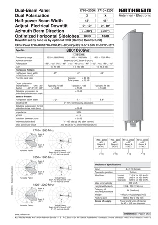
1. Type No. 80010606V01
Frequency range 1710 – 1880 MHz 1850 – 1990 MHz 1920 – 2200 MHz
Azimuth direction Beam A (–30°), Beam B (+30°)
Polarization +45°, –45°; +45°, –45° +45°, –45°; +45°, –45° +45°, –45°; +45°, –45°
Gain 4 x 19 dBi 4 x 19.3 dBi 4 x 19.5 dBi
Horizontal Pattern:
Half-power beam width
(offset beams ±30°)
47° 45° 43°
Front-to-back ratio Copolar: > 30 dB
Total power: > 25 dB
Cross polar ratio
Maindirection –30°; +30°
Sector –60°; 0°; 0°; +60°
Typically: 18 dB
> 13 dB
Typically: 17 dB
> 13 dB
Typically: 16 dB
> 13 dB
Sidelobe sppression for
sidelobes beside main beam
> 18 dB
Vertical Pattern:
Half-power beam width 7.2° 7.1° 6.8°
Electrical tilt 0°–10°, continuously adjustable
Sidelobe suppression for first
sidelobe above main beam > 18 dB
Impedance 50 Ω
VSWR < 1.5
Isolation, between ports > 30 dB
Intermodulation IM3 < –150 dBc (2 x 43 dBm carrier)
Max. power per input 200 W (at 50 °C ambient temperature)
KATHREIN-Werke KG · Anton-Kathrein-Straße 1 – 3 · P.O. Box 10 04 44 · 83004 Rosenheim · Germany · Phone +49 8031 184-0 · Fax +49 8031 184-973
www.kathrein.de
936.4001/cSubjecttoalteration.
XXPol Panel 1710–2200/1710–2200 45°(–30°)/45°(+30°) 19.5/19.5dBi 0°–10°/0°–10°T
1710–2200
Mechanical specifications
Input 4 x 7-16 female
Connector position Bottom
Wind load Frontal: 710 N (at 150 km/h)
Lateral: 200 N (at 150 km/h)
Rearside: 820 N (at 150 km/h)
Max. wind velocity 200 km/h
Height/width/depth 1314 / 380 / 150 mm
Category of
mounting hardware
M (Medium)
Weight 19 kg / 21 kg (clamps incl.)
Packing size 1696 x 402 x 172 mm
Scope of supply Panel and 2 units of clamps
for 42 – 115 mm diameter
80010606V01 Page 1 of 3
7-16 7-16
1710–2200
–45°
Beam B
(+30°)
1710–2200
+45°
Beam B
(+30°)
1710–2200
+45°
Beam A
(–30°)
1710–2200
–45°
Beam A
(–30°)
7-16 7-16
1710 – 1880 MHz
1850 – 1990 MHz
1920 – 2200 MHz
dB
3
10
47°
47°
7.2°
Bd
10
3
dB
3
10
45°
45°
dB
3
10
43°
43°
7.1°
Bd
10
3
6.8°
Bd
10
3
Horizontal Pattern Vertical Pattern
Beam A (–30°), Beam B (+30°)
0°–10° electrical downtilt
Vertical Pattern
Beam A (–30°), Beam B (+30°)
0°–10° electrical downtilt
Vertical Pattern
Beam A (–30°), Beam B (+30°)
0°–10° electrical downtilt
Horizontal Pattern
Horizontal Pattern
Dual-Beam Panel
Dual Polarization
Half-power Beam Width
Adjust. Electrical Downtilt
Azimuth Beam Direction
Optimized Horizontal Sidelobes
Downtilt set by hand or by optional RCU (Remote Control Unit)
1710–22001710–2200
XX
45°45°
0°–10°
(+30°)
18dB
0°–10°
(—30°)
18dB
Beam A
(–30°)
Beam A
(–30°)
Beam A
(–30°)
Beam B
(+30°)
Beam B
(+30°)
Beam B
(+30°)
2. KATHREIN-Werke KG · Anton-Kathrein-Straße 1 – 3 · P.O. Box 10 04 44 · 83004 Rosenheim · Germany · Phone +49 8031 184-0 · Fax +49 8031 184-973
www.kathrein.de
936.4001/cSubjecttoalteration.
Accessories
General Information
Adjustment
mechanism
with integrated scale
1314
9
1484
1514
64
For wall mounting: Azimuth Adjustment Kit 85010016.
For 3 Panel Arrangement: 3 Sector Clamp Kit 742034.
Material: Reflector screen: Tin-plated copper. Radiator: Tin-plated zinc.
Fiberglass radome: The grey fiberglass radomes of these antennas
are very stable and extraordinarily stiff. They are resistant to ultraviolet
radiation and can also be painted to match their surroundings.
All screws and nuts: Stainless steel.
Grounding: The metal parts of the antenna including the mounting kit and the inner
conductors are DC grounded.
Environmental conditions: Kathrein cellular antennas are designed to operate under the environ-
mental conditions as described in ETS 300 019-1-4 class 4.1 E.
The antennas exceed this standard with regard to the following items:
– Low temperature: –55 °C
– High temperature (dry): +60 °C
Ice protection: Due to the very sturdy antenna construction and the
protection of the radiating system by the radome, the antenna remains
operational even under icy conditions.
Environmental tests: Kathrein antennas have passed environmental tests as recommended
in ETS 300 019-2-4. The homogenous design of Kathrein’s antenna
families use identical modules and materials. Extensive tests have been
performed on typical samples and modules.
Layout of interface:
Please note: As a result of more stringent legal regulations and judgements regarding product liability, we are
obliged to point out certain risks that may arise when products are used under extraordinary operating
conditions.
The mechanical design is based on the environmental conditions as stipulated in ETS 300 019-1-4 and thereby
respects the static mechanical load imposed on an antenna by wind at maximum velocity. Wind loads are
calculated according to DIN 1055-4. Extraordinary operating conditions, such as heavy icing or exceptional
dynamic stress (e.g. strain caused by oscillating support structures), may result in the breakage of an antenna or
even cause it to fall to the ground. These facts must be considered during the site planning process.
The installation team must be properly qualified and also be familiar with the relevant national safety
regulations.
The details given in our data sheets have to be followed carefully when installing the antennas and
accessories.
The limits for the coupling torque of RF-connectors, recommended by the connector manufacturers must
be obeyed.
Any previous datasheet issues have now become invalid.
Page 2 of 3 80010606V01
Accessories
Type No. Description Remarks
Weight
approx.
Units per antenna
738546 1 clamp Mast: 42 – 115 mm diameter 1.1 kg 2 (included in the scope
of supply)
731651 1 clamp Mast: 28 – 60 mm diameter 0.8 kg 2 (order separately if required)
85010002 1 clamp Mast: 110 – 220 mm diameter 2.7 kg 2 (order separately if required)
85010003 1 clamp Mast: 210 – 380 mm diameter 4.8 kg 2 (order separately if required)
135
150
380 Bottom view
57
120
50
3. Proposal for
6 Sector Deployment
KATHREIN-Werke KG · Anton-Kathrein-Straße 1 – 3 · P.O. Box 10 04 44 · 83004 Rosenheim · Germany · Phone +49 8031 184-0 · Fax +49 8031 184-973
www.kathrein.de
936.4001/cSubjecttoalteration.
80010606V01 Page 3 of 3
Example of 6 Sectors by using 3x 80010606 and 3 Sector Clamp Kit 742034
For the above 3 Panel Arrangement please use the 3 Sector Clamp Kit 742034 (order separately)
30°
210°
60°
240°
90°270°
120°
300°
150°
330°
180°
0°
Antenna I
Beam A
Antenna II
Beam B
Antenna II
Beam A
Antenna III
Beam B
Antenna III
Beam A
Antenna I
Beam B
0
3
6
10
20
Horizontal Patterns (top view)
Bottom view
D
out
470
m
m
Antenna I
Antenna IIAntenna III
3 Sector Clamp Kit
Type No. 742034
Angle between antennas 120°
Suitable for mast diameter 139.7 mm
Type no. of pipe mast
(please order separately)
742036
Scope of supply 2 x 3 sector clamp
2 x mounting support clamp
Material – 3 sector clamp
– Mounting support
clamp
– Screws
– Nuts
Hot-dip galvanized steel
Aluminum
Hot-dip galvanized steel
Stainless steel
Outer diameter (Dout) of the
3 Dual-Beam Panel
Arrangement
470 mm
Weight – Clamp kit
– 3 sector clamp
4 kg
2 kg
3 Panel Arrangement
Mechanical specifications
Weight 60 kg
Wind load Frontal: 950 N (at 150 km)
Lateral: 950 N (at 150 km)
Rearside: 950 N (at 150 km)
Max. wind velocity 200 km/h
Type No. A B C D E F G
742034 139.7 100 236 228 64 50 45
all dimensions in mm
E
A
D
M8
B
C
60°
GF
Mounting support clamp
3 sector clamp
Torque
MA = 25 Nm
Torque
MA = 7 Nm
4. 936.4020Subjecttoalteration.
Page 1 of 1
KATHREIN-Werke KG . Anton-Kathrein-Straße 1 – 3 . P.O. Box 10 04 44 . 83004 Rosenheim . Germany . Phone +49 8031 184-0 . Fax +49 8031 184-973
Internet: www.kathrein.de
Remove the protective cap. Set downtilt angle by rotating the
adjustment wheel.
0° – max.°
max.° – 0°
Manual adjustment procedure:
General Instructions
for Adjustment Mechanism
Description of the adjustment mechanism (protective cap removed):
➀ Adjustment wheel with twist-lock
function.
➁ Downtilt spindle with integrated
scale.
➀ Thread for fixing the protective
cap or the RCU (Remote Control
Unit).
➁ Gearwheel for RCU power drive.
2
1
2
1
To set the downtilt angle exactly,
you must look horizontally at the
scale. The lower edge of the gear-
wheel must be used for alignment.
Optional: RCU (Remote Control Unit) for remote-controlled downtilt adjustment:
For a description of RCU installation please refer to the respective data sheet.
Screw on the protective cap again.