
Recommandé
Contenu connexe
Tendances
Tendances (20)
Similaire à Anesthesia Machine and their Anatomy
Similaire à Anesthesia Machine and their Anatomy (20)
Plus de Bangulkhanbaloch
Dernier
Dernier (20)
Anesthesia Machine and their Anatomy
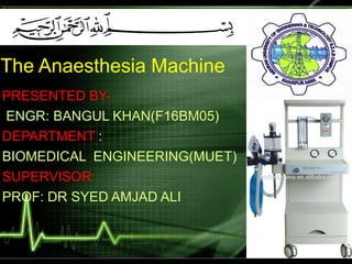
- 1. The Anaesthesia Machine PRESENTED BY- ENGR: BANGUL KHAN(F16BM05) DEPARTMENT : BIOMEDICAL ENGINEERING(MUET) SUPERVISOR: PROF: DR SYED AMJAD ALI
- 2. Anaesthesia Introduction An anesthesia workstation integrates most of the components necessary for administration of anesthesia into one unit It is a device which delivers a precisely-known but variable gas mixture, including anaesthetizing and life-sustaining gases. Consists of: The anesthesia machine Ventilator Breathing system Monitors Added to this may be drug delivery systems, suction equipment, and a data management system
- 3. WHY ANESTHESIA MACHINE IS USE IF THERE IS AVAILABILITY OF OTHER SIMPLE METHODS(CAUSES)
- 4. History The original concept of Boyle's machine was invented by the British anaesthetist H.E.G. Boyle in 1917 1920 – A vapourizing bottle is incorporated to the machine. 1926 – A 2nd vaporizing bottle and by-pass controls are incorporated. 1930 – A Plunger device is added to the vaporizing bottle. 1933 – A dry-bobbin type of flowmeter is introduced. 1937 – Rotameters displayed dry-bobbin type of flowmeters
- 5. Types of Anesthesia Machine Intermittent-Gas flows only during inspiration Egs: Entonox apparatus, Mackessons apparatus Continuous-Gas flows both during inspiration and expiration. Egs : Boyle Machine Forregar Dragger
- 6. Standards for Anesthesia Machines and Workstations Standards for anesthesia machines and workstations provide guidelines to manufacturers regarding their minimum performance, design characteristics, and safety requirements. During the past 2 decades, the progression of anesthesia machine standards has been as follows: 1979: American National Standards Institute 1988: American Society for Testing and Materials, 1994: ASTM F1161-94 (reapproved in 1994 and discontinued in 2000) 2005: International Electrical Commission (IEC) 2005: ASTM (reapproved)F1850 European standard is EN740
- 7. Contd…. To comply with the 2005 ASTM F1850-00 standard, newly manufactured workstations must have monitors that measure the following parameters: continuous breathing system pressure, exhaled tidal volume, ventilatory CO2 concentration, anesthetic vapor concentration, inspired oxygen concentration, oxygen supply pressure, arterial hemoglobin oxygen saturation arterial blood pressure, and continuous electrocardiogram.
- 10. Systemcomponents Electrical 1.Master Switch 2.Power Failure Indicator 3.Reserve Power 4.Electrical Outlet 5.Circuit Breakers 6.Data Communication Port Pneumatic 1.High Pressure System 2.Intermediate System 3.Low Pressure System
- 11. Electrical Components Master Switch Master (main power) switch activates both the pneumatic and electrical functions . On most machines, when the master switch is in the OFF position, the only electrical components that are active are the battery charger and the electrical outlets Standby position - allows the system to be powered up quickly Computer-driven machines should be turned OFF and restarted with a full checkout at least every 24 hours. STANDBY mode is not used for an extended period.
- 12. Most machines are equipped with a visual and/or audible indicator to alert the anesthesia provider to the loss of mains power . The machine will usually give an indication when mains power is lost. Power Failure Indicator Reserve Power Backup source of power for the occasional outage is necessary
- 13. Electrical Outlets Most modern anesthesia machines have electrical outlets. These are intended to power monitors and other devices. As a general rule, these outlets should only be used for anesthesia monitors. Other appliances should be connected directly to mains power. Next to each outlet is a circuit breaker.
- 14. Circuit Breakers There are circuit breakers for both the anesthesia machine and the outlets . When a circuit breaker is activated, the electrical load should be reduced and the circuit breaker reset Data Communication Ports Most modern anesthesia machines have data communications ports. These are used to communicate between the anesthesia machine, monitors, and the data management system
- 15. The anaesthesia machine receives medical gases from a gas supply; controls the flow of desired gases reducing their pressure, to a safe level. So the pressure inside a source ( cylinder or pipeline ) must be brought to a certain level before it can be used for the purpose of ventilation. And it needs to be supplied in a constant pressure, otherwise the flow meter would need continous adjustment. .
- 16. This is achieved by bringing down the pressure of a gas supply in a graded manner with the help of three pressure reducing zones . Thus the pneumatic part of the machine can be conveniently divided into three parts- High pressure system Intermediate pressure system Low pressure systems
- 18. • Consists of: – Hanger Yolk – Check valve – Cylinder Pressure Indicator (Gauge) – Pressure Reducing Device (Regulator) • Usually not used, unless pipeline gas supply is off
- 19. Hanger Yoke Assembly The Hanger yoke assembly 1) Orients and supports the cylinder 2) Provides a gas-tight seal 3) Ensures uni-directional gas flow The workstation standard recommends that there be at least one yoke each for oxygen and nitrous oxide. If the machine is likely to be used in locations that do not have piped gases, it is advisable to have a double yoke, especially for oxygen.
- 21. CHECK VALVE: It allows gas from a cylinder to enter the machine but prevents gas from exiting the machine when there is no cylinder in the yoke. It allows an empty cylinder to be replaced with a full one without having to turn off the `in–use` cylinder. Prevents transfer of gas from one cylinder to the other with a lower pressure in a double yoke. It consists of a plunger that slides away from the side of the greater pressure.
- 23. A Bourdon tube is a hollow metal tube(copper alloy) bent into a curve, then sealed on one side and linked to a clock like mechanism
- 24. Electronic Cylinder PressureIndicator Light emitting diodes(LED’S)in electronic pressure gauge indicate Cylinder valve is close –Dark color Cylinder valve is open – Pressure adequate –Green Pressure inadequate-Red
- 25. The pressure in a cylinder varies. The anesthesia machine is fitted with devices (reducing valves, regulators, reducing regulators, reduction valves, regulator valves) to maintain constant flow with changing supply pressure. These reduce the high and variable pressure found in a cylinder to a lower (40 to 48 psig, 272 to 336 kPa) and more constant pressure suitable for use in an anesthesia machine. PRESSURE REDUCING DEVICE (REGULATOR)
- 26. INTERMEDIATE PRESSURE SYSTEM Begins at the regulated cylinder supply source at 45 psig includes the pipeline sources at 50 to 55 psig and extends to the flow control valve.
- 27. Consists of: Pipeline inlet connections Pipeline pressure indicators Piping Gas power outlet Master switch Oxygen pressure failure devices Oxygen flush Additional reducing devices Flow control valves Check valve
- 28. MASTER SWITCH (PNEUMATIC COMPONENT ) The pneumatic portion of the master switch is located in the intermediate pressure system downstream of the inlets for the cylinder and pipeline supplies The oxygen flush is usually independent of this switch. The master switch may be a totally electronic switch that when activated controls the various pneumatic components in the anesthesia machine. When the master switch is turned off ,the pressure in the intermediate system will drop to zero
- 29. PIPELINE INLET CONNECTIONS It is the entry point for gases from the pipelines. The anesthesia workstation standard requires pipeline inlet connections for oxygen and nitrous oxide. A unidirectional (check) valve prevents reversed gas flow from the machine into the piping system Each pipeline inlet is required to have a filter with a pore size of 100μm or less. The filter may become clogged, resulting in a reduction in gas flow.
- 30. PIPELINE PRESSURE INDICATORS Indicators to monitor the pipeline pressure of each gas are required by the anesthesia workstation standard. They are usually found on a panel on the front of the machine and may be color coded for the gases that they monitor Pipeline pressure indicators should always be checked before the machine is used. The pressure should be between 50 and 55 psig (345 and 380 kPa). The indicators should be scanned repeatedly during use.
- 31. Piping is used to connect components inside the machine It must be able to withstand four times the intended service pressure Leaks between the pipeline inlet or cylinder pressure reducing system and the flow control valve not exceed 25 mL/minute If the yoke and pressure reducing system are included, the leakage may not exceed 150 mL/minute. PIPING
- 32. Some machines have gas selector switch that prevents air and nitrous oxide from being used together. GAS SELECTOR SWITCH GAS POWER OUTLET One or more gas power (auxiliary gas) outlets may be present on an anesthesia machine. It may serve as the source of driving gas for the anesthesia ventilator or to supply gas for a jet ventilator. Either oxygen or air may be used.
- 33. One of the most serious mishaps that occurred with early machines was depletion of the oxygen supply (usually from a cylinder) without the user awareness. The result was delivery of 100% anesthetic gas. Numerous inventions have been devised to prevent this Oxygen Failure Safety Device Oxygen Supply Failure Alarm OXYGEN PRESSURE FAILURE DEVICES
- 35. OXYGEN FLUSH The oxygen flush (oxygen bypass, emergency oxygen bypass) receives oxygen from the pipeline inlet or cylinder pressure regulator and directs a high unmetered flow directly to the common gas outlet. It is commonly labeled “02+.” On most anesthesia machines, the oxygen flush can be activated regardless of whether the master switch is turned ON or OFF. A flow between 35 and 75 L/minute must be delivered. The button is commonly recessed or placed in a collar to prevent accidental activation.
- 36. FLOW ADJUSTMENT CONTROL Controls flow of gas through it’s associated indicator by manual adjustment of a variable orifice Current standard requires that there be only one flow control for each gas. It must be adjusted or identifiable with its flow indicator
- 37. CONTROL KNOB Touch and colour coded joined to stem Large enough to be turned easily •Oxygen knob- Fluted Profile, as large/ larger than any other gas knob •Knobs turned counter clockwise- increase flow •Knobs turned clockwise decrease flow
- 38. LOW PRESSURE SYSTEM The low-pressure system is downstream of the flow control devices. Pressure in this section is only slightly above atmospheric and variable. Consists of: 1. Flowmeters 2. Hypoxia prevention safety devices 3. Unidirectional valve 4. Pressure relief devices 5. The common gas outlet 6. Vaporizers and their mounting devices
- 39. Flowmeters (flow indicators, flow tubes, rotameters) indicate the rate of flow of a gas passing through them. They may be mechanical or electronic. Electronic flowmeters usually have a representation of a mechanical flowmeter on a screen or a number representing the flow. FLOWMETER
- 40. Mechanical Flowmeters Measuring gas flow in a mechanical flowmeter is based on the principle that flow past a resistance is proportional to pressure. Mechanical flowmeters measure the drop in pressure that occurs when a gas passes through a resistance.
- 42. Physical Characteristics of the Gas At (low flows) flow is laminar and is a function of the viscosity of the gas (Hagen-Poiseuille equation). When the constriction is shorter and wider (high flows), flow is more turbulent and depends on gas density (Graham's law). Q is flow; n is viscosity; p/l is the pressure gradient; r is the radius of the tube
- 43. Physical Principle of Gas Flow Traditional mechanical flow indicators used in anesthesia machines have been of the variable orifice (variable area, Thorpe tube) type. A vertical glass tube is internally tapered with its smallest diameter at the bottom. It contains an indicator that is free to move up and down inside the tube. When there is no gas flow, the indicator rests at the bottom of the tube. When the flow control valve is opened, gas enters at the bottom and flows up the tube, elevating the indicator. Gas passes through the annular opening between the indicator and the tube and on to the outlet at the top of the tube.
- 45. UNIDIRECTIONAL CHECK VALVES When ventilation is controlled or assisted, positive pressure from the breathing system can be transmitted back into the machine. This pressure can affect flowmeter readings and the concentration of volatile anesthetic agents delivered from the vaporizers on the machine. This valve is located between the vaporizers and the common gas outlet, upstream of where the oxygen flush flow joins the fresh gas flow.
- 51. WORKING OF ANESTHESIA MACHINE