
Recommandé
Recommandé
Contenu connexe
Similaire à UNIT 2_DCN-converted.pdf
Similaire à UNIT 2_DCN-converted.pdf (20)
Plus de BhuvanaR13
Dernier
Dernier (20)
UNIT 2_DCN-converted.pdf
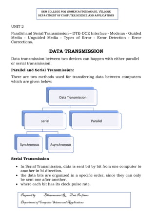
- 1. DKM COLLEGE FOR WOMEN(AUTONOMOUS), VELLORE DEPARTMENT OF COMPUTER SCIENCE AND APPLICATIONS Prepared by Bhuvaneswari R, Asst.Professor Department ofComputer Science and Applications UNIT 2 Parallel and Serial Transmission – DTE-DCE Interface - Modems - Guided Media - Unguided Media - Types of Error - Error Detection - Error Corrections. DATA TRANSMISSION Data transmission between two devices can happen with either parallel or serial transmission. Parallel and Serial Transmission: There are two methods used for transferring data between computers which are given below: Serial Transmission • In Serial Transmission, data is sent bit by bit from one computer to another in bi-direction. • the data bits are organized in a specific order, since they can only be sent one after another. • where each bit has its clock pulse rate. Data Transmission serial Synchronous Asynchronous Parallel
- 2. DKM COLLEGE FOR WOMEN(AUTONOMOUS), VELLORE DEPARTMENT OF COMPUTER SCIENCE AND APPLICATIONS Prepared by Bhuvaneswari R, Asst.Professor Department ofComputer Science and Applications • It is a reliable data transmission method because a data bit is only sent if the previous data bit has already been received. • Serial transmission is normally used for long-distance data transfer. • It ensures that data integrity • Serial transmission can be either synchronous or asynchronous. Synchronous Serial Transmission • In synchronous transmission, groups of bits are combined into frames and frames are sent continuously. • Data bits are transmitted as a continuous stream in time with a master clock. • i.e. The data transmitter and receiver both operate using a synchronized clock frequency. Advantages 1. data moves faster 2. timing errors are less frequent because the transmitter and receiver time is synced. 3. usually more expensive.
- 3. DKM COLLEGE FOR WOMEN(AUTONOMOUS), VELLORE DEPARTMENT OF COMPUTER SCIENCE AND APPLICATIONS Prepared by Bhuvaneswari R, Asst.Professor Department ofComputer Science and Applications Disadvantages: 1. data accuracy is highly dependent on timing being synced correctly between devices. Asynchronous Serial Transmission • In asynchronous transmission, groups of bits are sent as independent units with start/stop flags • Stop bits and start bits are used between data bytes to synchronize the transmitter and receiver and to ensure that the data is transmitted correctly. • The time between sending and receiving data bits is not constant, so gaps are used to provide time between transmissions. Advantages 1. No synchronization is required between the transmitter and receiver devices 2. Cost effective. Disadvantages: 1. Data transmission can be slower because of start/stop bit.
- 4. DKM COLLEGE FOR WOMEN(AUTONOMOUS), VELLORE DEPARTMENT OF COMPUTER SCIENCE AND APPLICATIONS Prepared by Bhuvaneswari R, Asst.Professor Department ofComputer Science and Applications Parallel Transmission • various bits are sent together simultaneously with a single clock pulse • i.e. multiple data bits are transmitted over multiple channels at the same time. • multiple bits are sent over multiple channels at the same time, the order in which a bit string is received can depend on various conditions, such as proximity to the data source, user location, and bandwidth availability. Advantages 1. Transmits data at a higher speed. 2. Suits better for short-distance communication. 3. Set of bits are transferred simultaneously. Disadvantages: 1. It is a costly transmission system. 2. In order to transmit the data over long ranges, the thickness of the wire has to be increased to diminish signal degradation. 3. There are multiple communication channels required.
- 5. DKM COLLEGE FOR WOMEN(AUTONOMOUS), VELLORE DEPARTMENT OF COMPUTER SCIENCE AND APPLICATIONS Prepared by Bhuvaneswari R, Asst.Professor Department ofComputer Science and Applications DTE-DCE INTERFACE As there is no direct technique is used for communication, so intermediary devices are used for communications. There are 4 basic functional units involved in communication of data: • A DTE and DCE on one end • A DTE and DCE on the other end DTE: Any device that is a source or destination of digital data DCE: Any device that transmits/receives signal through network Prepared by Bhuvaneswari R, Asst.Professor, Department of Computer Science and Applications • The DTE generates the data and passes it along with any control information to a DCE • The DCE converts the signal to a format appropriate to the Transmission medium and introduces it onto the network link • When the signal arrives at the receiving end this process is reversed DTE • DTE includes any unit that functions either as a source or as a destination for binary digital data
- 6. DKM COLLEGE FOR WOMEN(AUTONOMOUS), VELLORE DEPARTMENT OF COMPUTER SCIENCE AND APPLICATIONS Prepared by Bhuvaneswari R, Asst.Professor Department ofComputer Science and Applications • At the physical layer, it cab a terminal, microcomputer, computer , printer or any other device that generates or consumes digital data • DTEs do not often communicate with each other directly with each other DCE • DCE includes any functional unit that transmits or receives data in the form of an analog or digital signal through a network • At the physical layer, a DCE takes data generated by a DTE, converts it to the appropriate signal and then introduces it to the communication link • Commonly used DCEs at the physical layer include MODEMS • In any n/w , a DTE generates digital data and passes it on to a DCE, the DCE converts the data to a form acceptable to the TX medium and sends the converted signal to another DCE on the network • The second DCE takes the signal off, converts it to a suitable form for its DTE and delivers it • To make this communication possible, the sending and receiving DCEs must use the same modulation method. • The two DTEs need not be coordinated with each other but they need to be coordinated with their respective DCEs and the DCEs must be coordinated so that data translation occurs without loss of integrity. Differences between DCE and DTE DTE DCE DTE is an abbreviation of 'Data Terminal Equipment' or 'Data Terminating Equipment' DCE is an abbreviation of 'Data Circuit Terminal Equipment' or 'Data Communication Equipment'. It is a device that either works as a source and destination. It is a device that is used for transmitting digital data. This equipment connects through the DCE (Data Communication Equipment) network. his equipment acts as an intermediary between the two networks of DTE.
- 7. DKM COLLEGE FOR WOMEN(AUTONOMOUS), VELLORE DEPARTMENT OF COMPUTER SCIENCE AND APPLICATIONS Prepared by Bhuvaneswari R, Asst.Professor Department ofComputer Science and Applications Its devices produce the data and transfer the data to DCE. Its devices convert the signals to the transmission medium and introduce it onto the telecommunication or network line. Computers, printers, FAX, and routers are some examples of DTE devices. Modem, satellites, and ISDN adaptors are some examples of DCE devices. MODEMS • MODEM full form is “Modulator-Demodulator” • it has ability to modulates and demodulates analog carrier signals for encoding and decoding digital data. • Modem is a hardware networking device that helps to make connection with computer or other hardware components like as switch or router for linking to internet. Purpose of Modem • Modems are used for performing both activities like as sending and receiving of the digital data in between with multiple computer systems. • Then this data is transmitted over the telephone lines with using V.92, to analog modems which helping out for converting those signals back to digital form for readable format to computer. • Modem plays role as digital translator that helps to get all information signals from cable, fiber or telephone line and convert it into accessible form for your PCs.
- 8. DKM COLLEGE FOR WOMEN(AUTONOMOUS), VELLORE DEPARTMENT OF COMPUTER SCIENCE AND APPLICATIONS Prepared by Bhuvaneswari R, Asst.Professor Department ofComputer Science and Applications Types of Modem There are different types of modem which are used in computer networking; below explain each one – Dial-up Modem: Dial-up modems transmits analog signal via telephone lines. This modem is uses mostly to make connection with ISP using of analog signals. Dial- up modem has two variant like as external or internal modem. Cable Modem: In the cable modem, to use the coaxial cables those are connected to the back edge of modem. ADSL Modem: ADSL stands for “Asymmetric Digital Subscriber Line” and these types of modems uses the telephone line for sending and receiving all information. ASDL modems have higher speed compare to conventional voice and modem. ASDL modem uses two types of data transmission methods like as “Synchronous and Asynchronous“. Synchronous transmission is used into more accurate for your timing signals but asynchronous transmission is used into mistaken correcting formulas.
- 9. DKM COLLEGE FOR WOMEN(AUTONOMOUS), VELLORE DEPARTMENT OF COMPUTER SCIENCE AND APPLICATIONS Prepared by Bhuvaneswari R, Asst.Professor Department ofComputer Science and Applications DSL Modem: DSL stands for “Digital Subscriber Line“, and it is also known as “Broadband Modem“. DSL modems offer broadband services for using of different types of internet connections. DSL modems are comfortable for higher internet speed. External Modem: External modem likes as standalone modem because it doesn’t integrate any router. This modem is connected with the computer through USB stick, WIFI or Ethernet cable. It has option for getting connection with separate router, if you want to share make connection with several network terminals around small zone. Router/Modem Combo: This type of modem is contained with router that allows several devices and computers to attach within single network. So, users do not require a extra router and modem. Integrated Modem: This modem is embedded into computer in the form of USB or PCI card. But, this type of modem allows only single computer system to make connection with internet. Onboard Modem: Onboard modems are embedded onto motherboard, so this modem has not any chance for removing, but it can be disable with using of jumper or BIOS setup. Removable Modem: This modem can be inserted or removed as per the requirement, and these modems are used into traditional laptops PCMCIA slot. Wireless Modem:
- 10. DKM COLLEGE FOR WOMEN(AUTONOMOUS), VELLORE DEPARTMENT OF COMPUTER SCIENCE AND APPLICATIONS Prepared by Bhuvaneswari R, Asst.Professor Department ofComputer Science and Applications Wireless Modem is also known as “Radiofrequency Modem“, and these modems are developed to work with cellular technology and wireless local area networks. Fax Modem: Fax modem is used for transmitting and receiving any document over the telephone line, and this modem works like as fax machine. ISDN Modem: ISDN stands for “Integrated Services Digital Network“, and it provides to make communication standards for using of digital transmission of voice, video data over wire or optical fiber. Intelligent Modems: Intelligent Modems are more costly to other modem because it is able to diagnostic error checking within the modem itself. This modem consists internal read only memory (ROM) coding and microprocessor chips to offer sophisticated communications protocols. Functions of Modem Here, we will explain various functions of modem in computer networking, such as – Data Compression: To decrease the amount of time when it try to send data and for cutting down on the percentages of errors in the all flowing of signals, then modem required the data compression mechanism. So, this data compression method helps to reduce the size of signals, which are required for sending data. Error Correction: In the error correction techniques, all devices monitor all information while receiving is undamaged. It splits all information into small units that is called the “Frames“. In this process, it tags all frames along with checksums, but it is done before sending information. Checksum is a
- 11. DKM COLLEGE FOR WOMEN(AUTONOMOUS), VELLORE DEPARTMENT OF COMPUTER SCIENCE AND APPLICATIONS Prepared by Bhuvaneswari R, Asst.Professor Department ofComputer Science and Applications special technique that helps to check redundancy in the presented data in the computer. If, this information matches with checksums then device grabs the verified information. That is sent by error-correcting modem. But, if it gets to fail in matching with checksum then information is moved back. Modulate Signals: The main function of modem is to transmit and decode all signals which allow sending digital data from one node to other nodes without getting any damage of information. Flow Control: Each modem has different speed of sending signals. so, it can generate issues during to receive signals if any one device’s speed down of them. So, in the flow control technique, slower one signals the faster one to pause, by sending a ‘character’. If, slow device will try to send character to faster modem, then this character would be a signal to the faster modem for Pausing the information transfer until the slow modem gets caught up. Other important functions are: • To modify the digital data such as (0s and 1s) into accurate analog signals • Help to line control and signaling to other edges of phone line. • If, modems are made to dial up then it can send dialing signal without knowing of users. • Help to provide security while line overloading and other issues. TRANSMISSION MEDIA o Transmission media is a communication channel that carries the information from the sender to the receiver. Data is transmitted through the electromagnetic signals. o It is a physical path between transmitter and receiver in data communication.
- 12. DKM COLLEGE FOR WOMEN(AUTONOMOUS), VELLORE DEPARTMENT OF COMPUTER SCIENCE AND APPLICATIONS Prepared by Bhuvaneswari R, Asst.Professor Department ofComputer Science and Applications o The characteristics and quality of data transmission are determined by the characteristics of medium and signal. o Different transmission media have different properties such as bandwidth, delay, cost and ease of installation and maintenance. o The transmission media is available in the lowest layer of the OSI reference model, i.e., Physical layer. Some factors need to be considered for designing the transmission media: o Bandwidth: All the factors are remaining constant, the greater the bandwidth of a medium, the higher the data transmission rate of a signal. o Transmission impairment: When the received signal is not identical to the transmitted one due to the transmission impairment. The quality of the signals will get destroyed due to transmission impairment. o Interference: An interference is defined as the process of disrupting a signal when it travels over a communication medium on the addition of some unwanted signal. Transmission Impairment: o Attenuation: Attenuation means the loss of energy, i.e., the strength of the signal decreases with increasing the distance which causes the loss of energy. o Distortion: Distortion occurs when there is a change in the shape of the signal. This type of distortion is examined from different
- 13. DKM COLLEGE FOR WOMEN(AUTONOMOUS), VELLORE DEPARTMENT OF COMPUTER SCIENCE AND APPLICATIONS Prepared by Bhuvaneswari R, Asst.Professor Department ofComputer Science and Applications signals having different frequencies. Each frequency component has its own propagation speed, so they reach at a different time which leads to the delay distortion. o Noise: When data is travelled over a transmission medium, some unwanted signal is added to it which creates the noise. Classification Of Transmission Media: Guided Media It is defined as the physical medium through which the signals are transmitted. It is also known as Bounded media. Types Of Guided media: Twisted pair: Twisted pair is a physical media made up of a pair of cables twisted with each other. A twisted pair cable is cheap as compared to other transmission media. Installation of the twisted pair cable is easy, and it is a lightweight cable. The frequency range for twisted pair cable is from 0 to 3.5KHz. A twisted pair consists of two insulated copper wires arranged in a regular spiral pattern.
- 14. DKM COLLEGE FOR WOMEN(AUTONOMOUS), VELLORE DEPARTMENT OF COMPUTER SCIENCE AND APPLICATIONS Prepared by Bhuvaneswari R, Asst.Professor Department ofComputer Science and Applications Types of Twisted pair: Unshielded Twisted Pair: An unshielded twisted pair is widely used in telecommunication. Following are the categories of the unshielded twisted pair cable: o Category 1: Category 1 is used for telephone lines that have low- speed data. o Category 2: It can support upto 4Mbps. o Category 3: It can support upto 16Mbps. o Category 4: It can support upto 20Mbps. Therefore, it can be used for long-distance communication. o Category 5: It can support upto 200Mbps. Advantages Of Unshielded Twisted Pair: o It is cheap. o Installation of the unshielded twisted pair is easy. o It can be used for high-speed LAN. Disadvantage:
- 15. DKM COLLEGE FOR WOMEN(AUTONOMOUS), VELLORE DEPARTMENT OF COMPUTER SCIENCE AND APPLICATIONS Prepared by Bhuvaneswari R, Asst.Professor Department ofComputer Science and Applications o This cable can only be used for shorter distances because of attenuation. Shielded Twisted Pair A shielded twisted pair is a cable that contains the mesh surrounding the wire that allows the higher transmission rate. Characteristics Of Shielded Twisted Pair: o The cost of the shielded twisted pair cable is not very high and not very low. o An installation of STP is easy. o It has higher capacity as compared to unshielded twisted pair cable. o It has a higher attenuation. o It is shielded that provides the higher data transmission rate. Disadvantages o It is more expensive as compared to UTP and coaxial cable. o It has a higher attenuation rate. Coaxial Cable o Coaxial cable is very commonly used transmission media, for example, TV wire is usually a coaxial cable. o The name of the cable is coaxial as it contains two conductors parallel to each other. o It has a higher frequency as compared to Twisted pair cable. o The inner conductor of the coaxial cable is made up of copper, and the outer conductor is made up of copper mesh. The middle core is made up of non-conductive cover that separates the inner conductor from the outer conductor. o The middle core is responsible for the data transferring whereas the copper mesh prevents from the EMI(Electromagnetic interference).
- 16. DKM COLLEGE FOR WOMEN(AUTONOMOUS), VELLORE DEPARTMENT OF COMPUTER SCIENCE AND APPLICATIONS Prepared by Bhuvaneswari R, Asst.Professor Department ofComputer Science and Applications Coaxial cable is of two types: 1. Baseband transmission: It is defined as the process of transmitting a single signal at high speed. 2. Broadband transmission: It is defined as the process of transmitting multiple signals simultaneously. Advantages Of Coaxial cable: o The data can be transmitted at high speed. o It has better shielding as compared to twisted pair cable. o It provides higher bandwidth. Disadvantages Of Coaxial cable: o It is more expensive as compared to twisted pair cable. o If any fault occurs in the cable causes the failure in the entire network. Fibre Optic o Fibre optic cable is a cable that uses electrical signals for communication. o Fibre optic is a cable that holds the optical fibres coated in plastic that are used to send the data by pulses of light. o The plastic coating protects the optical fibres from heat, cold, electromagnetic interference from other types of wiring. o Fibre optics provide faster data transmission than copper wires. Diagrammatic representation of fibre optic cable:
- 17. DKM COLLEGE FOR WOMEN(AUTONOMOUS), VELLORE DEPARTMENT OF COMPUTER SCIENCE AND APPLICATIONS Prepared by Bhuvaneswari R, Asst.Professor Department ofComputer Science and Applications Basic elements of Fibre optic cable: o Core: The optical fibre consists of a narrow strand of glass or plastic known as a core. A core is a light transmission area of the fibre. The more the area of the core, the more light will be transmitted into the fibre. o Cladding: The concentric layer of glass is known as cladding. The main functionality of the cladding is to provide the lower refractive index at the core interface as to cause the reflection within the core so that the light waves are transmitted through the fibre. o Jacket: The protective coating consisting of plastic is known as a jacket. The main purpose of a jacket is to preserve the fibre strength, absorb shock and extra fibre protection. o Following are the advantages of fibre optic cable over copper: o Greater Bandwidth: The fibre optic cable provides more bandwidth as compared copper. Therefore, the fibre optic carries more data as compared to copper cable. o Faster speed: Fibre optic cable carries the data in the form of light. This allows the fibre optic cable to carry the signals at a higher speed. o Longer distances: The fibre optic cable carries the data at a longer distance as compared to copper cable.
- 18. DKM COLLEGE FOR WOMEN(AUTONOMOUS), VELLORE DEPARTMENT OF COMPUTER SCIENCE AND APPLICATIONS Prepared by Bhuvaneswari R, Asst.Professor Department ofComputer Science and Applications o Better reliability: The fibre optic cable is more reliable than the copper cable as it is immune to any temperature changes while it can cause obstruct in the connectivity of copper cable. o Thinner and Sturdier: Fibre optic cable is thinner and lighter in weight so it can withstand more pull pressure than copper cable. UnGuided Transmission o An unguided transmission transmits the electromagnetic waves without using any physical medium. Therefore it is also known as wireless transmission. o In unguided media, air is the media through which the electromagnetic energy can flow easily. Unguided transmission is broadly classified into three categories: Radio waves o Radio waves are the electromagnetic waves that are transmitted in all the directions of free space. o Radio waves are omnidirectional, i.e., the signals are propagated in all the directions. o The range in frequencies of radio waves is from 3Khz to 1 khz. o In the case of radio waves, the sending and receiving antenna are not aligned, i.e., the wave sent by the sending antenna can be received by any receiving antenna. o An example of the radio wave is FM radio.
- 19. DKM COLLEGE FOR WOMEN(AUTONOMOUS), VELLORE DEPARTMENT OF COMPUTER SCIENCE AND APPLICATIONS Prepared by Bhuvaneswari R, Asst.Professor Department ofComputer Science and Applications Applications Of Radio waves: o A Radio wave is useful for multicasting when there is one sender and many receivers. o An FM radio, television, cordless phones are examples of a radio wave. Advantages Of Radio transmission: o mainly used for wide area networks and mobile cellular phones. o it cover a large area, and they can penetrate through walls. o It provides a higher transmission rate. Disadvantages of Radio Wave • Insecure communication medium • Prone to weather changes like rain, thunderstorms, etc.
- 20. DKM COLLEGE FOR WOMEN(AUTONOMOUS), VELLORE DEPARTMENT OF COMPUTER SCIENCE AND APPLICATIONS Prepared by Bhuvaneswari R, Asst.Professor Department ofComputer Science and Applications Microwaves Microwaves are of two types Terrestrial Microwave Transmission o Terrestrial Microwave transmission is a technology that transmits the focused beam of a radio signal from one ground-based microwave transmission antenna to another. o Microwaves are the electromagnetic waves having the frequency in the range from 1GHz to 1000 GHz. o Microwaves are unidirectional as the sending and receiving antenna is to be aligned, i.e., the waves sent by the sending antenna are narrowly focussed. o In this case, antennas are mounted on the towers to send a beam to another antenna which is km away. o It works on the line of sight transmission, i.e., the antennas mounted on the towers are the direct sight of each other. Characteristics of Microwave: o Frequency range: The frequency range of terrestrial microwave is from 4-6 GHz to 21-23 GHz. o Bandwidth: It supports the bandwidth from 1 to 10 Mbps. o Short distance: It is inexpensive for short distance. o Long distance: It is expensive as it requires a higher tower for a longer distance.
- 21. DKM COLLEGE FOR WOMEN(AUTONOMOUS), VELLORE DEPARTMENT OF COMPUTER SCIENCE AND APPLICATIONS Prepared by Bhuvaneswari R, Asst.Professor Department ofComputer Science and Applications o Attenuation: Attenuation means loss of signal. It is affected by environmental conditions and antenna size. Advantages Of Microwave: o Microwave transmission is cheaper than using cables. o It is free from land acquisition as it does not require any land for the installation of cables. o Microwave transmission provides an easy communication in terrains as the installation of cable in terrain is quite a difficult task. o Communication over oceans can be achieved by using microwave transmission. Disadvantages of Microwave transmission: o Eavesdropping: An eavesdropping creates insecure communication. Any malicious user can catch the signal in the air by using its own antenna. o ut of phase signal: A signal can be moved out of phase by using microwave transmission. o Susceptible to weather condition: A microwave transmission is susceptible to weather condition. This means that any environmental change such as rain, wind can distort the signal. o Bandwidth limited: Allocation of bandwidth is limited in the case of microwave transmission. Satellite Microwave Communication o A satellite is a physical object that revolves around the earth at a known height. o Satellite communication is more reliable nowadays as it offers more flexibility than cable and fibre optic systems. o We can communicate with any point on the globe by using satellite communication.
- 22. DKM COLLEGE FOR WOMEN(AUTONOMOUS), VELLORE DEPARTMENT OF COMPUTER SCIENCE AND APPLICATIONS Prepared by Bhuvaneswari R, Asst.Professor Department ofComputer Science and Applications How Does Satellite work? The satellite accepts the signal that is transmitted from the earth station, and it amplifies the signal. The amplified signal is retransmitted to another earth station. Advantages Of Satellite Microwave Communication: o The coverage area of a satellite microwave is more than the terrestrial microwave. o The transmission cost of the satellite is independent of the distance from the centre of the coverage area. o Satellite communication is used in mobile and wireless communication applications. o It is easy to install. o It is used in a wide variety of applications such as weather forecasting, radio/TV signal broadcasting, mobile communication, etc. Disadvantages Of Satellite Microwave Communication: o Satellite designing and development requires more time and higher cost. o The Satellite needs to be monitored and controlled on regular periods so that it remains in orbit. o The life of the satellite is about 12-15 years. Due to this reason, another launch of the satellite has to be planned before it becomes non-functional. Infrared o An infrared transmission is a wireless technology used for communication over short ranges. o The frequency of the infrared in the range from 300 GHz to 400 THz.
- 23. DKM COLLEGE FOR WOMEN(AUTONOMOUS), VELLORE DEPARTMENT OF COMPUTER SCIENCE AND APPLICATIONS Prepared by Bhuvaneswari R, Asst.Professor Department ofComputer Science and Applications o It is used for short-range communication such as data transfer between two cell phones, TV remote operation, data transfer between a computer and cell phone resides in the same closed area. Characteristics Of Infrared: o It supports high bandwidth, and hence the data rate will be very high. o Infrared waves cannot penetrate the walls. Therefore, the infrared communication in one room cannot be interrupted by the nearby rooms. o An infrared communication provides better security with minimum interference. o Infrared communication is unreliable outside the building because the sun rays will interfere with the infrared waves. ERROR CONTROL Data-link layer uses error control techniques to ensure that frames, i.e. bit streams of data, are transmitted from the source to the destination with a certain extent of accuracy. Errors o When bits are transmitted over the computer network, they are subject to get corrupted due to interference and network problems. o The corrupted bits leads to spurious data being received by the destination and are called errors. Types of Errors Errors can be of three types, namely single bit errors, multiple bit errors, and burst errors.
- 24. DKM COLLEGE FOR WOMEN(AUTONOMOUS), VELLORE DEPARTMENT OF COMPUTER SCIENCE AND APPLICATIONS Prepared by Bhuvaneswari R, Asst.Professor Department ofComputer Science and Applications • Single bit error − In the received frame, only one bit has been corrupted, i.e. either changed from 0 to 1 or from 1 to 0. • Multiple bits error − In the received frame, more than one bits are corrupted. • Burst error − In the received frame, more than one consecutive bits are corrupted. Error Control Error control can be done in two ways • Error detection − Error detection involves checking whether any error has occurred or not. The number of error bits and the type of error does not matter.
- 25. DKM COLLEGE FOR WOMEN(AUTONOMOUS), VELLORE DEPARTMENT OF COMPUTER SCIENCE AND APPLICATIONS Prepared by Bhuvaneswari R, Asst.Professor Department ofComputer Science and Applications • Error correction − Error correction involves ascertaining the exact number of bits that has been corrupted and the location of the corrupted bits. Error Detecting Techniques: The most popular Error Detecting Techniques are: o Single parity check o Two-dimensional parity check o Checksum o Cyclic redundancy check 1.Single Parity Check o Single Parity checking is the simple mechanism and inexpensive to detect the errors. o In this technique, a redundant bit is also known as a parity bit which is appended at the end of the data unit so that the number of 1s becomes even. Therefore, the total number of transmitted bits would be 9 bits. o If the number of 1s bits is odd, then parity bit 1 is appended and if the number of 1s bits is even, then parity bit 0 is appended at the end of the data unit. o At the receiving end, the parity bit is calculated from the received data bits and compared with the received parity bit. o This technique generates the total number of 1s even, so it is known as even-parity checking.
- 26. DKM COLLEGE FOR WOMEN(AUTONOMOUS), VELLORE DEPARTMENT OF COMPUTER SCIENCE AND APPLICATIONS Prepared by Bhuvaneswari R, Asst.Professor Department ofComputer Science and Applications Drawbacks Of Single Parity Checking o It can only detect single-bit errors which are very rare. o If two bits are interchanged, then it cannot detect the errors. 2.Two-Dimensional Parity Check o Performance can be improved by using Two-Dimensional Parity Check which organizes the data in the form of a table. o Parity check bits are computed for each row, which is equivalent to the single-parity check. o In Two-Dimensional Parity check, a block of bits is divided into rows, and the redundant row of bits is added to the whole block.
- 27. DKM COLLEGE FOR WOMEN(AUTONOMOUS), VELLORE DEPARTMENT OF COMPUTER SCIENCE AND APPLICATIONS Prepared by Bhuvaneswari R, Asst.Professor Department ofComputer Science and Applications o At the receiving end, the parity bits are compared with the parity bits computed from the received data. Drawbacks Of 2D Parity Check o If two bits in one data unit are corrupted and two bits exactly the same position in another data unit are also corrupted, then 2D Parity checker will not be able to detect the error. o This technique cannot be used to detect the 4-bit errors or more in some cases. 3.Checksum A Checksum is an error detection technique based on the concept of redundancy. It is divided into two parts: Checksum Generator A Checksum is generated at the sending side. Checksum generator subdivides the data into equal segments of n bits each, and all these segments are added together by using one's complement arithmetic. The sum is complemented and appended to the original data, known as checksum field. The extended data is transmitted across the network.
- 28. DKM COLLEGE FOR WOMEN(AUTONOMOUS), VELLORE DEPARTMENT OF COMPUTER SCIENCE AND APPLICATIONS Prepared by Bhuvaneswari R, Asst.Professor Department ofComputer Science and Applications The Sender follows the given steps: 1. The block unit is divided into k sections, and each of n bits. 2. All the k sections are added together by using one's complement to get the sum. 3. The sum is complemented and it becomes the checksum field. 4. The original data and checksum field are sent across the network. Checksum Checker A Checksum is verified at the receiving side. The receiver subdivides the incoming data into equal segments of n bits each, and all these segments are added together, and then this sum is complemented. If the complement of the sum is zero, then the data is accepted otherwise data is rejected. The Receiver follows the given steps: 1. The block unit is divided into k sections and each of n bits. 2. All the k sections are added together by using one's complement 3. algorithm to get the sum. 4. The sum is complemented. 5. If the result of the sum is zero, then the data is accepted otherwise the data is discarded.
- 29. DKM COLLEGE FOR WOMEN(AUTONOMOUS), VELLORE DEPARTMENT OF COMPUTER SCIENCE AND APPLICATIONS Prepared by Bhuvaneswari R, Asst.Professor Department ofComputer Science and Applications Cyclic Redundancy Check (CRC) CRC is a redundancy error technique used to determine the error. Following are the steps used in CRC for error detection: o In CRC technique, a string of n 0s is appended to the data unit, and this n number is less than the number of bits in a predetermined number, known as division which is n+1 bits. o Secondly, the newly extended data is divided by a divisor using a process is known as binary division. The remainder generated from this division is known as CRC remainder. o Thirdly, the CRC remainder replaces the appended 0s at the end of the original data. This newly generated unit is sent to the receiver. o The receiver receives the data followed by the CRC remainder. The receiver will treat this whole unit as a single unit, and it is divided by the same divisor that was used to find the CRC remainder. If the resultant of this division is zero which means that it has no error, and the data is accepted. o If the resultant of this division is not zero which means that the data consists of an error. Therefore, the data is discarded. o o Let's understand this concept through an example:
- 30. DKM COLLEGE FOR WOMEN(AUTONOMOUS), VELLORE DEPARTMENT OF COMPUTER SCIENCE AND APPLICATIONS Prepared by Bhuvaneswari R, Asst.Professor Department ofComputer Science and Applications o Suppose the original data is 11100 and divisor is 1001. CRC Generator o A CRC generator uses a modulo-2 division. Firstly, three zeroes are appended at the end of the data as the length of the divisor is 4 and we know that the length of the string 0s to be appended is always one less than the length of the divisor. o Now, the string becomes 11100000, and the resultant string is divided by the divisor 1001. o The remainder generated from the binary division is known as CRC remainder. The generated value of the CRC remainder is 111. o CRC remainder replaces the appended string of 0s at the end of the data unit, and the final string would be 11100111 which is sent across the network. CRC Checker o The functionality of the CRC checker is similar to the CRC generator. o When the string 11100111 is received at the receiving end, then CRC checker performs the modulo-2 division. o A string is divided by the same divisor, i.e., 1001. o In this case, CRC checker generates the remainder of zero. Therefore, the data is accepted.
- 31. DKM COLLEGE FOR WOMEN(AUTONOMOUS), VELLORE DEPARTMENT OF COMPUTER SCIENCE AND APPLICATIONS Prepared by Bhuvaneswari R, Asst.Professor Department ofComputer Science and Applications ERROR CORRECTION Error Correction codes are used to detect and correct the errors when data is transmitted from the sender to the receiver. Error Correction can be handled in two ways: o Backward error correction: Once the error is discovered, the receiver requests the sender to retransmit the entire data unit. o Forward error correction: In this case, the receiver uses the error- correcting code which automatically corrects the errors. A single additional bit can detect the error, but cannot correct it. For correcting the errors, one has to know the exact position of the error. For example, If we want to calculate a single-bit error, the error correction code will determine which one of seven bits is in error. To achieve this, we have to add some additional redundant bits. Suppose r is the number of redundant bits and d is the total number of the data bits. The number of redundant bits r can be calculated by using the formula:
- 32. DKM COLLEGE FOR WOMEN(AUTONOMOUS), VELLORE DEPARTMENT OF COMPUTER SCIENCE AND APPLICATIONS Prepared by Bhuvaneswari R, Asst.Professor Department ofComputer Science and Applications 2r>=d+r+1 The value of r is calculated by using the above formula. For example, if the value of d is 4, then the possible smallest value that satisfies the above relation would be 3. To determine the position of the bit which is in error, a technique developed by R.W Hamming is Hamming code which can be applied to any length of the data unit and uses the relationship between data units and redundant units. HAMMING CODE Parity bits: The bit which is appended to the original data of binary bits so that the total number of 1s is even or odd. Even parity: To check for even parity, if the total number of 1s is even, then the value of the parity bit is 0. If the total number of 1s occurrences is odd, then the value of the parity bit is 1. Odd Parity: To check for odd parity, if the total number of 1s is even, then the value of parity bit is 1. If the total number of 1s is odd, then the value of parity bit is 0. Algorithm of Hamming code: o An information of 'd' bits are added to the redundant bits 'r' to form d+r. o The location of each of the (d+r) digits is assigned a decimal value. o The 'r' bits are placed in the positions 1,2,.....2k-1. o At the receiving end, the parity bits are recalculated. The decimal value of the parity bits determines the position of an error.
- 33. DKM COLLEGE FOR WOMEN(AUTONOMOUS), VELLORE DEPARTMENT OF COMPUTER SCIENCE AND APPLICATIONS Prepared by Bhuvaneswari R, Asst.Professor Department ofComputer Science and Applications Relationship b/w Error position & binary number. Let's understand the concept of Hamming code through an example: Suppose the original data is 1010 which is to be sent. Total number of data bits 'd' = 4 Number of redundant bits r : 2r >= d+r+1 2r>= 4+r+1 Therefore, the value of r is 3 that satisfies the above relation. Total number of bits = d+r = 4+3 = 7; Determining the position of the redundant bits The number of redundant bits is 3. The three bits are represented by r1, r2, r4. The position of the redundant bits is calculated with corresponds to the raised power of 2. Therefore, their corresponding positions are 1, 21 , 22 . 1. The position of r1 = 1 2. The position of r2 = 2 3. The position of r4 = 4 Representation of Data on the addition of parity bits:
- 34. DKM COLLEGE FOR WOMEN(AUTONOMOUS), VELLORE DEPARTMENT OF COMPUTER SCIENCE AND APPLICATIONS Prepared by Bhuvaneswari R, Asst.Professor Department ofComputer Science and Applications Determining the Parity bits Determining the r1 bit The r1 bit is calculated by performing a parity check on the bit positions whose binary representation includes 1 in the first position. We observe from the above figure that the bit positions that includes 1 in the first position are 1, 3, 5, 7. Now, we perform the even-parity check at these bit positions. The total number of 1 at these bit positions corresponding to r1 is even, therefore, the value of the r1 bit is 0. Determining r2 bit The r2 bit is calculated by performing a parity check on the bit positions whose binary representation includes 1 in the second position. We observe from the above figure that the bit positions that includes 1 in the second position are 2, 3, 6, 7. Now, we perform the even-parity check at these bit positions. The total number of 1 at these bit positions corresponding to r2 is odd, therefore, the value of the r2 bit is 1.
- 35. DKM COLLEGE FOR WOMEN(AUTONOMOUS), VELLORE DEPARTMENT OF COMPUTER SCIENCE AND APPLICATIONS Prepared by Bhuvaneswari R, Asst.Professor Department ofComputer Science and Applications Determining r4 bit The r4 bit is calculated by performing a parity check on the bit positions whose binary representation includes 1 in the third position. We observe from the above figure that the bit positions that includes 1 in the third position are 4, 5, 6, 7. Now, we perform the even-parity check at these bit positions. The total number of 1 at these bit positions corresponding to r4 is even, therefore, the value of the r4 bit is 0. Data transferred is given below: Suppose the 4th bit is changed from 0 to 1 at the receiving end, then parity bits are recalculated. R1 bit The bit positions of the r1 bit are 1,3,5,7
- 36. DKM COLLEGE FOR WOMEN(AUTONOMOUS), VELLORE DEPARTMENT OF COMPUTER SCIENCE AND APPLICATIONS Prepared by Bhuvaneswari R, Asst.Professor Department ofComputer Science and Applications We observe from the above figure that the binary representation of r1 is 1100. Now, we perform the even-parity check, the total number of 1s appearing in the r1 bit is an even number. Therefore, the value of r1 is 0. R2 bit The bit positions of r2 bit are 2,3,6,7. We observe from the above figure that the binary representation of r2 is 1001. Now, we perform the even-parity check, the total number of 1s appearing in the r2 bit is an even number. Therefore, the value of r2 is 0. R4 bit The bit positions of r4 bit are 4,5,6,7. We observe from the above figure that the binary representation of r4 is 1011. Now, we perform the even-parity check, the total number of 1s appearing in the r4 bit is an odd number. Therefore, the value of r4 is 1. o The binary representation of redundant bits, i.e., r4r2r1 is 100, and its corresponding decimal value is 4. Therefore, the error occurs in a
- 37. DKM COLLEGE FOR WOMEN(AUTONOMOUS), VELLORE DEPARTMENT OF COMPUTER SCIENCE AND APPLICATIONS Prepared by Bhuvaneswari R, Asst.Professor Department ofComputer Science and Applications 4th bit position. The bit value must be changed from 1 to 0 to correct the error. 2 mark Questions: 1. Define serial transmission 2. Define parallel transmission 3. Expand DTE-DCE? Why it is used? 4. What is the use of modems? 5. State the uses of ISDN and DSL modems 6. What are the types of twisted pair cables 7. Define error 8. Define the types of error 9. Define error detection 10. Define error correction 11. Name the techniques that are used to detect errors. 12. What are the two error correction methods used. Define them 10/5 marks 1. explain serial and parallel transmission 2. explain transmission medium with neat diagrams 3. explain error detection techniques 4. explain error correcting technique 5.