
Recommandé
Contenu connexe
Similaire à Shift control mechanism audi a4 b5
Similaire à Shift control mechanism audi a4 b5 (20)
Plus de Bogdan Alexandru
Dernier
Dernier (20)
Shift control mechanism audi a4 b5
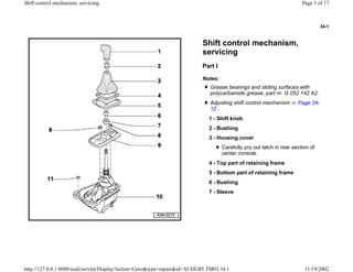
- 1. 34-1 Shift control mechanism, servicing Part I Notes: Grease bearings and sliding surfaces with polycarbamide grease, part nr. G 052 142 A2. Adjusting shift control mechanism Page 34- 12 . 1 - Shift knob 2 - Bushing 3 - Housing cover Carefully pry out latch in rear section of center console 4 - Top part of retaining frame 5 - Bottom part of retaining frame 6 - Bushing 7 - Sleeve Page 1 of 17Shift control mechanism, servicing 11/19/2002http://127.0.0.1:8080/audi/servlet/Display?action=Goto&type=repair&id=AUDI.B5.TM03.34.1
- 2. 34-2 8 - Nut, 8 Nm 9 - Noise insulation cover 10 - Shift control mechanism with shift housing 11 - Nut, 10 Nm Page 2 of 17Shift control mechanism, servicing 11/19/2002http://127.0.0.1:8080/audi/servlet/Display?action=Goto&type=repair&id=AUDI.B5.TM03.34.1
- 3. 34-3 Part II 1 - Shift control mechanism with shift housing 2 - Tensioning ring 3 - Boot Carefully pull over shift rod during removal Set onto marks of shift rod and pivot rod when installing 4 - Socket head bolt, 25 Nm 5 - Clamp 6 - Shift rod Do not disconnect connecting rod Fig. -8- from shift rod; observe note Page 34-9 Page 3 of 17Shift control mechanism, servicing 11/19/2002http://127.0.0.1:8080/audi/servlet/Display?action=Goto&type=repair&id=AUDI.B5.TM03.34.1
- 4. 34-4 7 - Nut, 25 Nm 8 - Connecting rod Do not disconnect from shift rod; observe note Page 34-9 9 - Bolt, 25 Nm 10 - Washer 11 - Socket head bolt, 25 Nm 12 - Front shift rod With bearing bushing, bolt and washers 13 - Bolt, 40 Nm Part of front shift rod Page 4 of 17Shift control mechanism, servicing 11/19/2002http://127.0.0.1:8080/audi/servlet/Display?action=Goto&type=repair&id=AUDI.B5.TM03.34.1
- 5. 34-5 Selector mechanism, removing and installing Removing - Unscrew shift knob from shift lever. Note: Shift cover is removed together with the cover for center console. - Slightly lift off cover for center console upward (arrows -A-). - Pull cover slightly toward back (arrow -B-), then lift complete cover upward. Page 5 of 17Shift control mechanism, servicing 11/19/2002http://127.0.0.1:8080/audi/servlet/Display?action=Goto&type=repair&id=AUDI.B5.TM03.34.1
- 6. 34-6 - Remove noise insulation cover for shift mechanism housing (arrows). - Unscrew nuts securing shift mechanism housing (arrows). Page 6 of 17Shift control mechanism, servicing 11/19/2002http://127.0.0.1:8080/audi/servlet/Display?action=Goto&type=repair&id=AUDI.B5.TM03.34.1
- 7. 34-7 Repair Manual, 2.7 Liter V6 5V BiTurbo Engine Mechanical, Engine Code(s): APB, Repair Group 26 - Remove heat shield for left-hand inner joint -1- from transmission (arrows). - Disconnect left-hand drive axle -1-, lift toward front and tie up. - Remove rear section of exhaust system (rearward of exhaust pipe clamp(s)): - Remove heat shield above driveshaft. - Remove heat shield for driveshaft from cover for Torsen differential (arrows). - Remove driveshaft Page 39-68 . Page 7 of 17Shift control mechanism, servicing 11/19/2002http://127.0.0.1:8080/audi/servlet/Display?action=Goto&type=repair&id=AUDI.B5.TM03.34.1
- 8. 34-8 - Unscrew bolts -1- and -2- on left and right. - Lower subframe at the rear. -a- = max. 50 mm Page 8 of 17Shift control mechanism, servicing 11/19/2002http://127.0.0.1:8080/audi/servlet/Display?action=Goto&type=repair&id=AUDI.B5.TM03.34.1
- 9. 34-9 Important notice for the following procedures: Under no circumstances may the ball head (arrow -A-) of connecting rod - 2- be pulled off shift rod -1- during removal of shift linkage. The ball head is destroyed when pulled off. Nut (arrow -B-) and Bolt (arrow -C-)must be removed to remove shift rod. - Unbolt connecting rod -2- on right-hand side of transmission. - Remove hex socket head bolt from push rod -1-. Page 9 of 17Shift control mechanism, servicing 11/19/2002http://127.0.0.1:8080/audi/servlet/Display?action=Goto&type=repair&id=AUDI.B5.TM03.34.1
- 10. 34-10 Installing Installation is carried out in the reverse order, when doing this note the following: Repair Manual, 2.7 Liter V6 5V BiTurbo Engine Mechanical, Engine Code(s): APB, Repair Group 26 - Unscrew nut -1- and pull selector rod lever -2- off transmission selector shaft. - Swing gear shift housing with selector rod and push rod down and remove. - Bolt on driveshaft Page 39-71 . - Adjust driveshaft Page 39-75 . - Adjust gear selector mechanism Page 34-12 . - Align exhaust system free of stress Page 10 of 17Shift control mechanism, servicing 11/19/2002http://127.0.0.1:8080/audi/servlet/Display?action=Goto&type=repair&id=AUDI.B5.TM03.34.1
- 11. 34-11 Tightening torques Component Nm Hex bolt -1- 75 Combi bolt -2- 110 + 90 Gear shift housing to body 10 Selector rod to transmission 25 Connecting rod to transmission 25 Push rod to transmission 40 Drive axle to drive flange M8 M10 40 80 Heat shield for drive axle 25 Clamp for exhaust pipe 40 Page 11 of 17Shift control mechanism, servicing 11/19/2002http://127.0.0.1:8080/audi/servlet/Display?action=Goto&type=repair&id=AUDI.B5.TM03.34.1
- 12. 34-12 Gear selector mechanism, adjusting Requirements Selector mechanism, operating and relay elements must be in proper condition. Selector mechanism must move freely. Transmission, clutch and clutch mechanism must be in proper condition. Transmission in neutral. - Unscrew gear shift knob from gear shift. - Remove cover (gaiter) for gear shift. - Remove noise insulation for selector mechanism housing (arrows). Page 12 of 17Shift control mechanism, servicing 11/19/2002http://127.0.0.1:8080/audi/servlet/Display?action=Goto&type=repair&id=AUDI.B5.TM03.34.1
- 13. 34-13 - Measure distance between body and rear push rod (in selector mechanism). If that is not the case, obtain distance -a- as follows: Specification: distance a = 43 mm - Loosen bolt (arrow) for pivot rod. Rear pivot rod (in shift control mechanism) must move freely back and forth on sliding piece. - Adjust measurement -a- by moving pivot rod rear (in shift control mechanism). - Tighten bolt for pivot rod to 25 Nm. Page 13 of 17Shift control mechanism, servicing 11/19/2002http://127.0.0.1:8080/audi/servlet/Display?action=Goto&type=repair&id=AUDI.B5.TM03.34.1
- 14. 34-14 - Loosen bolt for selector rod (arrow). Connection between selector rod and selector mechanism should move freely. - Adjust gear shift as follows: Note: The illustration shows the gear shift from behind (looking towards the front of the vehicle). Gear shift vertical, maximum inclination of 3 to the right (angle ) Page 14 of 17Shift control mechanism, servicing 11/19/2002http://127.0.0.1:8080/audi/servlet/Display?action=Goto&type=repair&id=AUDI.B5.TM03.34.1
- 15. 34-15 Note: The illustration shows the gear shift from the right. Note: The gear shift must remain in the same position while the bolt is being tightened. Gear shift inclined slightly backwards (approx. 7 , angle b) - Hold gear shift in this position. - Tighten selector rod bolt to 25 Nm. Page 15 of 17Shift control mechanism, servicing 11/19/2002http://127.0.0.1:8080/audi/servlet/Display?action=Goto&type=repair&id=AUDI.B5.TM03.34.1
- 16. 34-16 Gear shift adjustment, checking The gear shift lever must rest in the 3rd/4th gear gate when transmission is in neutral. - Check operation of 1st and 2nd gear stop. - Engage 2nd gear and push gear shift to the left against the stop. - Reduce pressure on gear shift until it moves back to pressure point. Spring-back measured at gear shift handle: 3-5 mm - Check that all gears can be engaged. - Check operation of reverse gear lock. It should only be possible to engage reverse gear after pressing the gear shift down to overcome the reverse gear lock. It must be possible to move the gear shift, without pushing and without force, forwards from the reverse gear lock to the 3rd/4th gear plane Page 16 of 17Shift control mechanism, servicing 11/19/2002http://127.0.0.1:8080/audi/servlet/Display?action=Goto&type=repair&id=AUDI.B5.TM03.34.1
- 17. 34-17 If the gear shift setting is incorrect it can be adjusted as follows: Note: The angle of forwards/backwards inclination of the gear shift must not be changed while the following adjustments are being made. - Loosen bolt for selector rod (arrow). Tightening torques - Move gear shift to the left or to the right until distance "x" is 8.5 mm. - Hold gear shift in this position. - Tighten selector rod bolt. Component Nm Selector rod to selector fork (in selector mechanism) 25 - Check gear shift setting again. - Fit covers and gear shift knob. Page 17 of 17Shift control mechanism, servicing 11/19/2002http://127.0.0.1:8080/audi/servlet/Display?action=Goto&type=repair&id=AUDI.B5.TM03.34.1