1. HOW TO READ THE STANDARD
OF THREADING
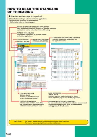
a How this section page is organized
zClassified according to external or internal applications.
xSub-classified according to product series.
(Refer to the index on the next page.)
FIGURE SHOWING THE TOOLING APPLICATION
uses illustrations and arrows to depict the available machining
applications, such as external and internal threading.
TYPE OF TOOL HOLDER
indicates the initial letters for the order number
and cutting applications.
STANDARDS FOR APPLICABLE INSERTS
TITLE OF PRODUCT INDICATION OF EXTERNAL indicates stock status, dimensions, etc.
PRODUCT SECTION /INTERNAL APPLICATION for applicable inserts.
EXTERNAL THREADING
MMTE HOLDER
MMTE External threading
INTERNAL THREADING INSERTS
Coated Dimensions (mm) Total
Type
Pitch Cutting
VP20RT
VP15TF
Order Number Depth Geometry
D1 S1 Z1 Z2 Re
mm thread/inch (mm)
Details of position A Partial Profile 60° MMT11IRA60-S a 0.5 ─ 1.5 48 ─ 16 6.35 3.04 0.8 0.9 0.03 ─ Partial form
Refer to page G014, G016,
G018, G020 for size Z1, Z2. 16IRA60-S a 0.5 ─ 1.5 48 ─ 16 9.525 3.44 0.8 0.9 0.03 ─
16IRG60-S a 1.75─3.0 14 ─ 8 9.525 3.44 1.2 1.7 0.11 ─
Right hand tool holder only.
* * z
Stock
Dimensions (mm)
Order Number Insert Number x
R H1 B L1 L2 H2 F1 Clamp Clamp Stop Shim Screw Shim Wrench
Bridge Screw Ring
zTKY15F MMT11IRA55-S a 48 ─ 16 6.35 3.04 0.8 0.9 0.07 ─ Partial form
Partial Profile 55°
MMTER1212H16-C a 12 12 100 25 12 16 SETK51 SETS51 CR4 HFC03008 CTE32TP15 xHKY20R 16IRA55-S a 48 ─ 16 9.525 3.44 0.8 0.9 0.07 ─
zTKY15F
1616H16-C a 16 16 100 25 16 20 SETK51 SETS51 CR4 HFC03008 CTE32TP15 a
xHKY20R 16IRG55-S 14 ─ 8 9.525 3.44 1.2 1.7 0.21 ─
MMT16ER zTKY15F
2020K16-C a 20 20 125 26 20 25 SETK51 SETS51 CR4 HFC03008 CTE32TP15 xHKY20R
ppppp zTKY15F
2525M16-C a 25 25 150 28 25 32 SETK51 SETS51 CR4 HFC03008 CTE32TP15 xHKY20R
zTKY15F
3232P16-C a 32 32 170 32 32 40 SETK51 SETS51 CR4 HFC03008 CTE32TP15 xHKY20R
zTKY20F
MMTER2525M22-C a 25 25 150 32 25 32 SETK61 SETS61 CR5 HFC04010 CTE43TP15 a
xHKY25R MMT11IR100ISO-S 1.0 6.35 3.04 0.6 0.7 0.06 0.58 Full form
MMT22ER zTKY20F
THREADING
THREADING
3232P22-C a 32 32 170 32 32 40 SETK61 SETS61 CR5 HFC04010 CTE43TP15 11IR125ISO-S a 1.25 6.35 3.04 0.8 0.9 0.08 0.72
ppppp xHKY25R
zTKY20F 11IR150ISO-S a 1.5 6.35 3.04 0.8 1.0 0.10 0.87
4040R22-C a 40 40 200 38 40 50 SETK61 SETS61 CR5 HFC04010 CTE43TP15 xHKY25R
16IR100ISO-S a a 1.0 9.525 3.44 0.6 0.7 0.06 0.58
ISO Metric
(Note) Select and use a shim as shown below (sold separately), dependant on the lead angle.
16IR125ISO-S a a 1.25 9.525 3.44 0.8 0.9 0.08 0.72
Clamp Torque (N • m) : SETS51=3.5, SETS61=5.0, HFC03008=1.5, HFC04010=2.2
* 16IR150ISO-S a a 1.5 9.525 3.44 0.8 1.0 0.10 0.87
16IR175ISO-S a a 1.75 9.525 3.44 0.9 1.2 0.11 1.01
SHIM a a
16IR200ISO-S 2.0 9.525 3.44 1.0 1.3 0.13 1.15
Lead Stock Inclination Applicable Lead Stock Inclination Applicable a a
Angle Order Number Angle Angle Order Number Angle 16IR250ISO-S 2.5 9.525 3.44 1.1 1.5 0.17 1.44
(%°) R ('° ) Holder (%°) R ('° ) Holder a a
16IR300ISO-S 3.0 9.525 3.44 1.1 1.5 0.20 1.73
─1.5° CTE32TN15 a ─3° ─1.5° CTE43TN15 a ─3° MMT16IR160UN-S a 16 9.525 3.44 0.9 1.1 0.11 0.92 Full form
─0.5° N05 a ─ 2° ─0.5° N05 a ─2° Insert
16IR140UN-S a 14 9.525 3.44 0.9 1.2 0.12 1.05
American UN
0.5° P05 a ─ 1° MMTER 0.5° P05 a ─1° MMTER Inclination
16IR120UN-S a 12 9.525 3.44 1.1 1.4 0.14 1.22
1.5° P15 a 0° ppppp 1.5° P15 a 0° ppppp Angle Shim
('°)
2.5° P25 a 1° 16-C 2.5° P25 a 1° 22-C
3.5° P35 a 2° 3.5° P35 a 2°
4.5° P45 a 3° 4.5° P45 a 3°
Standard shim delivered with the holder.
Whitworth for BSW, BSP
MMT16IR190W-S a 19 9.525 3.44 0.8 1.0 0.18 0.86 Full form
a
IDENTIFICATION 16IR140W-S 14 9.525 3.44 1.0 1.2 0.25 1.16
16IR110W-S a 11 9.525 3.44 1.1 1.5 0.32 1.48
MMT E R 12 12 H 16 C
Designation Application Hand of Tool Tool Size (mm) Tool Length Insert Size Method of
E External R Right (Height and Width) (mm) (mm) Holding MMT16IR190BSPT-S a 19 9.525 3.44 0.8 0.9 0.18 0.86 Full form
12 12 H 100 16 9.525 C Clamp-on 16IR140BSPT-S a 14 9.525 3.44 1.0 1.2 0.25 1.16
16 16 K 125 22 12.7 16IR110BSPT-S a 11 9.525 3.44 1.1 1.5 0.32 1.48
BSPT
20 20 M 150
25 25 P 170
32 32 R 200
40 40
RECOMMENDED CUTTING CONDITIONS
Work Material Hardness Grade Cutting Speed (m/min) Work Material Hardness Grade Cutting Speed (m/min)
P VP10MF 150 (70 ─ 230) S VP10MF 45 (15 ─ 70)
Mild Steel < 180HB VP15TF 100 (60 ─ 140) Heat-Resistant Alloy ─ VP15TF
30 (20 ─ 40)
VP20RT 80 (60 ─ 100) VP20RT
VP10MF 140 (80 ─ 200) VP10MF 60 (40 ─ 80)
Carbon Steel • 180 ─ 280HB VP15TF 100 (60 ─ 140) Titanium Alloy ─ VP15TF
Alloy Steel 45 (25 ─ 65)
VP20RT 80 (60 ─ 100) VP20RT
M VP15TF H Heat-Treated Alloy VP10MF 50 (30 ─ 70)
Stainless Steel < 200HB 80 (40 ─ 120) 45 ─ 55HRC
VP20RT VP15TF 40 (20 ─ 60)
K Tensile Strength VP10MF 140 (80 ─ 200)
Gray Cast Iron < 350MPa VP15TF 90 (60 ─ 120)
a : Inventory maintained in Japan.
G012 CUTTING DEPTH GUIDE G040 G015
LEGEND FOR STOCK PAGE REFERENCE
STATUS MARK · SPARE PARTS
is shown on the left hand page indicates reference pages, including the above,
of each double-page spread. on the right hand page of each double-page spread.
PRODUCT STANDARDS RECOMMENDED CUTTING CONDITIONS
indicates order numbers, stock status for each work material classification, indicates recommended
(per right/left hand), applicable inserts, cutting conditions according to the ISO categories for
holder dimensions, and spare parts. cutting grades, P, M, K, S, and H.
a To Order : For holder, please specify zorder number and hand of tool (right/left).
For insert, please specify zinsert number and xgrade.
G000
2. TURNING TOOLS
THREADING
CLASSIFICATION (EXTERNAL THREADING) ................ G002
CLASSIFICATION (INTERNAL THREADING) ................. G003
CROSS REFERENCE OF THREAD PITCHES
EXTERNAL ............................................. G004
INTERNAL .............................................. G006
STANDARD THREAD AND CORRESPONDING INSERT • HOLDER ... G008
STANDARD OF THREADING TOOLS
FEATURES OF MMT SERIES ............................... G010
EXTERNAL THREADING
MMTE HOLDER .......................................... G012
MT HOLDER ............................................... G022
SMG HOLDER ............................................ G024
INTERNAL THREADING
MMTI TYPE BORING BARS ............................. G013
MICRO-MINI TWIN BORING BARS .............. G026
F TYPE BORING BARS .................................... G030
D TYPE BORING HEAD ................................... G032
THREADING METHOD.......................................... G034
STANDARD OF DEPTH OF CUT .......................... G038
TROUBLE SHOOTING .......................................... G042
*Arranged by Alphabetical order
G026 CT
G032 DPT2
G030 FSL51
G030 FSL52
G031 MLG (INSERTS)
G031 MLP (INSERTS)
G031 MLT (INSERTS)
G014 MMT (INSERTS)
G012 MMTE
G013 MMTI
G022 MT1
G022 MTH
G023 MTT (INSERTS)
G033 MTT (INSERTS)
G028 RBH
G029 SBH
G024 SMGH
G025 SMGT (INSERTS)
G025 SMTT (INSERTS)
G001
3. THREADING
CLASSIFICATION (EXTERNAL THREADING)
Shank Size
Name of Tool Holder Insert Shape Features (H x W x L)
(mm)
MMTE Holder a Various insert types.
a M-class 3-D breaker inserts and G-class
12 x 12 x 100
16 x 16 x 100
ground inserts available.
20 x 20 x 125
a Available with a wiper cutting edge to
25 x 25 x 150
provide a precise thread geometry.
32 x 32 x 170
a Able to change lead angle by replacing
40 x 40 x 200
^ G012 shim.
MT Holder a Clamp-on type.
a Precision class insert.
16 x 16 x 100
a Positive insert suffers from negligible
20 x 20 x 125
chattering and thus produces good
25 x 25 x 150
finished surface.
32 x 32 x 170
^ G022
THREADING
SMG Holder a Screw-on type.
a Precision class insert. 10 x 10 x 70
a Positive insert suffers from negligible 12 x 12 x 80
chattering and thus produces good 16 x 16 x 100
finished surface. 20 x 20 x 125
a Holder is capable of performing both 25 x 25 x 150
^ G024 threading and grooving.
TTAH aTools to be equipped on Gang type tool posts.
a Small Shank: 8mm─16mm
a High rigidity due to designing of vertical insert. 8 x 10 x 120
a The screw designed for common use on 10 x 10 x 120
front and back enables back clamping. 12 x 12 x 120
a Most suitable for threading diameters of
SMALL TOOLS
16 x 16 x 120
2 mm or smaller.
^ D024 a Screw-on type.
CSVH a Tools to be equipped on Cam type tool posts.
a Small Shank: 7mm─12mm 7 x 7 x 140
a Single holder for front turning, 8 x 8 x 140
back turning, grooving, threading and
9.5 x 9.5 x 140
cutting off operations.
a The most suitable for machining of small 10 x 10 x 140
parts with work diameter & 5mm or less. 12 x 12 x 140
^ D027 a Screw-on type.
G002
4. CLASSIFICATION (INTERNAL THREADING)
Shank Size
(Dia. x L x Min.
Name of Tool Holder Insert Shape Features Cutting Dia.)
(mm)
MMTI a Minimum cutting diameter 12mm.
a Various insert types.
16 x 125 x 13
16 x 150 x 15
a M-class 3-D breaker inserts and G-class 20 x 170 x 24
ground inserts available.
25 x 200 x 29
a Available with a wiper cutting edge to
provide a precise thread geometry. 32 x 250 x 37
^ G013 a Able to change lead angle by replacing shim. 40 x 300 x 46
FSL5 a Minimum cutting diameter 10mm.
a Screw-on type.
8 x 125 x 10
10 x 150 x 12
a Precision class insert.
12 x 180 x 14
a Applicable for threading, grooving and boring.
14 x 180 x 16
a Available with a carbide shank to prevent
16 x 200 x 20
^ G030 vibration when machining deep holes.
DPT2 a Minimum cutting diameter 40mm.
a Pin lock type.
THREADING
32 x 300 x 40
a Precision class insert.
40 x 360 x 50
a Exchangeable head type.
^ G032
MICRO-MINI TWIN a Minimum cutting diameter 3mm.
Boring Bars 3 x 50 x 3
a Solid carbide type.
4 x 60 x 4.5
─ a Economical two cutting edge type. 5 x 70 x 6
6 x 75 x 7
^ G026
MICRO-MINI a Minimum cutting diameter 3.2mm.
Boring Bars
a Solid carbide type. 3 x 80 x 3.2
─ a Insert can be ground to suit the 4 x 80 x 4.2
application. 5 x 100 x 5.2
^ E022
G003
5. THREADING
CROSS REFERENCE THREAD PITCH (EXTERNAL)
Pipe fittings and couplings
Application General machining for gas and water
Partial Profile Partial Profile ISO Metric American Parallel American
60° 55° UN Pipe Thread NPT
Whitworth
for BSW, BSP
Type
M G
UNC
Symbol UNC W M
UNF
Rp NPT
UNF W
Pitch mm thread/inch mm thread/inch thread/inch thread/inch
Holder (thread/inch)
THREADING
MMT Holder Full
form
─ ─ 0.5 ─ 5.0 32 ─ 5 28 ─ 5
27, 18, 14
11.5, 8
Partial 0.5 ─ 5.0
─ ─
(48 ─ 5) 48 ─ 5 0.5 ─ 5.0 48 ─ 5
^ G012 form
MT Holder
Partial 0.25 ─ 4.5
20 ─ 9 0.25 ─ 4.5 64 ─ 6 ─ ─
form (64 ─ 6)
^ G022
SMG Holder
Partial 0.25 ─ 2.0
─ 0.25 ─ 2.0 48 ─ 13 ─ ─
form (48 ─ 13)
^ G024
G004
6. Pipe couplings
Steam, gas Aircraft and
for food and fire Motion transmissions Oil and gas
and water line pipes fighting industries aerospace
Taper Pipe American Round ISO American UNJ API Buttress API Round
Thread NPTF DIN 405 Trapezoidal ACME Casing Casing&Tubing
BSPT 30°
R CSG
NPTF Rd Tr ACME UNJ BCSG
Rc LCSG
thread/inch thread/inch thread/inch mm thread/inch thread/inch thread/inch thread/inch
THREADING
28, 19 27, 18, 14 10, 8 1.5, 2 12, 10
14, 11 11.5, 8 6, 4 3, 4, 5 32 ─ 8 5 10, 8
8, 6, 5
─ ─ ─ ─ ─ ─ ─ ─
─ ─ ─ ─ ─ ─ ─ ─
─ ─ ─ ─ ─ ─ ─ ─
G005
7. THREADING
CROSS REFERENCE THREAD PITCH (INTERNAL)
Pipe fittings and couplings
Application General machining for gas and water
Partial Profile Partial Profile ISO Metric American Parallel American
60° 55° UN Pipe Thread NPT
Whitworth
for BSW, BSP
Type
M G
UNC
Symbol UNC W M
UNF
Rp NPT
UNF W
Pitch mm thread/inch mm thread/inch thread/inch thread/inch
Holder (thread/inch)
THREADING
MMT Full
form
─ ─ 0.5 ─ 5.0 32 ─ 5 28 ─ 5
27, 18, 14
Boring Bars 11.5, 8
Partial 0.5 ─ 5.0
─ ─
(48 ─ 5) 48 ─ 5 0.5 ─ 5.0 48 ─ 5
^ G013 form
FSL5
Boring Bars Partial 1.5 ─ 3.5
─ 1.5 ─ 3.5 16 ─ 8 ─ ─
form (16 ─ 8)
^ G030
DPT2
Boring Partial 0.25 ─ 4.5
Head ─ 0.25 ─ 4.5 64 ─ 6 ─ ─
form (64─ 6)
^ G032
MICRO-MINI
TWIN Partial 0.5 ─ 1.75
─ 0.5 ─ 1.75 36 ─ 16 ─ ─
form (36 ─ 16)
^ G026
G006
8. Pipe couplings
Steam, gas Aircraft and
for food and fire Motion transmissions Oil and gas
and water line pipes fighting industries aerospace
Taper Pipe American Round ISO American UNJ API Buttress API Round
Thread NPTF DIN 405 Trapezoidal ACME Casing Casing&Tubing
BSPT 30°
R CSG
NPTF Rd Tr ACME UNJ BCSG
Rc LCSG
thread/inch thread/inch thread/inch mm thread/inch thread/inch thread/inch thread/inch
THREADING
10, 8 1.5, 2 12, 10
19, 14, 11 14, 11.5, 8 ─ 5 10, 8
6, 4 3, 4, 5 8, 6, 5
─ ─ ─ ─ ─ * ─ ─ ─
─ ─ ─ ─ ─ ─ ─ ─
─ ─ ─ ─ ─ ─ ─ ─
─ ─ ─ ─ ─ ─ ─ ─
* In this machining an internalinsertthread, cut used. hole with the appropriate diameter. Then machine with 60° American UN.
When
case, a full form type
UNJ
cannot be
an internal
G007
9. THREADING
STANDARD THREAD AND CORRESPONDING INSERT • HOLDER
Thread Wiper/
Standard Thread Type Type Ext./Int. Insert Number Tool Holder Page
Name General
MMTooERoooISO Wiper
MMTooERoooISO-S Wiper
MMTERooooo-C G012
MMTooERooo60 General
Internal
Ext. MMTooERooo60-S General
thread SMTTR/L160360oo General SMGHR/Loooo16 G024
ISO Metric
MTHR/Looooo4
M MTTR/L4360oo General G022
MT1R/Looooo4
d or D
External thread
d1 or D1
MMTooIRoooISO Wiper
d2 or D2 MMTooIRoooISO-S Wiper MMTIRooAooo-SPo
G013
H=0.866025P d2=d-0.649519P Int. MMTooIRooo60 General MMTIRooAo16-C
H1=0.541266P d1=d-1.082532P
D=d D2=d2 D1=d1 MMTooIRooo60-S General
MTTR/L4360oo General DPT2oooR G032
MMTooERoooUN Wiper
MMTooERoooUN-S Wiper
MMTERooooo-C G012
MMTooERooo60 General
Internal
thread Ext. MMTooERooo60-S General
American UN
SMTTR/L160360oo General SMGHR/Loooo16 G024
UNC MTHR/Looooo4
THREADING
d or D
External thread MTTR/L4360oo General G022
UNF MT1R/Looooo4
d1 or D1
d2 or D2
MMTooIRoooUN Wiper
MMTooIRoooUN-S Wiper MMTIRooAooo-SPo
H=0.866025×25.4/n d2=(d-0.649519/n)×25.4
G013
H1=0.541266×25.4/n d1=(d-1.082532/n)×25.4
Int. MMTooIRooo60 General MMTIRooAo16-C
d=(d)×25.4 D=d D2=d2 D1=d1 P=25.4/ thread MMTooIRooo60-S General
MTTR/L4360oo General DPT2oooR G032
MMTooERoooW Wiper
MMTooERoooW-S Wiper
Whitworth for BSW, BSP
MMTERooooo-C G012
Internal MMTooERooo55 General
thread Ext.
MMTooERooo55-S General
MTHR/Looooo4
MTTR/L4355oo General G022
W MT1R/Looooo4
d or D
External thread
MMTooIRoooW Wiper
d1 or D1
d2 or D2
MMTooIRoooW-S Wiper MMTIRooAooo-SPo
G013
H=0.9605P d2=d-H1 d1=d-2H1 r=0.1373P Int. MMTooIRooo55 General MMTIRooAo16-C
H1=0.6403P D1'=d1+2×0.0769H
D=d D2=d2 D1=d1 P=25.4/ thread MMTooIRooo55-S General
MTTR/L4355oo General DPT2oooR G032
Wiper : Insert order number is determined by selected pitch.
General : An insert is applicable to several pitch types.
G008
10. Thread Wiper/
Standard Thread Type Type Ext./Int. Insert Number Tool Holder Page
Name General
MMTooERoooW Wiper
Parallel Pipe Thread
Internal
thread
Ext. MMTERooooo-C G012
PF MMTooERoooW-S Wiper
G
d or D
External thread Rp MMTooIRoooW Wiper
MMTIRooAooo-SPo
d1 or D1
d2 or D2
Int. G013
MMTIRooAo16-C
H=0.960491P d2=d-h d1=d-2h r=0.137329P MMTooIRoooW-S Wiper
h=0.640327 D=d D2=d2 D1=d1 25.4/ thread
Internal MMTooERoooBSPT Wiper
thread
Ext. MMTERooooo-C G012
MMTooERoooBSPT-S Wiper
BSPT
BSPT
MMTooIRoooBSPT Wiper
MMTIRooAooo-SPo
Int. G013
Thread center axis MMTIRooAo16-C
MMTooIRoooBSPT-S Wiper
THREADING
H=0.960237P h=0.640327 r=0.137278P P=25.4/ thread
Internal
thread
Ext. MMTooERoooRD Wiper MMTERooooo-C G012
Round DIN 405
Rd
External
MMTIRooAooo-SPo
thread Int. MMTooIRoooRD Wiper G013
MMTIRooAo16-C
ac=0.05×P h3=H4=0.5×P
R1=0.238507×P R2=0.255967×P R3=0.221047×P
ISO Trapezoidal 30°
Internal Ext. MMTooERoooTR Wiper MMTERooooo-C G012
thread
Tr
d or D
External
thread
MMTIRooAooo-SPo
d2 or D2
Int. MMTooIRoooTR Wiper G013
d1 or D1
MMTIRooAo16-C
Internal
thread
Ext. MMTooERoooACME Wiper MMTERooooo-C G012
American ACME
ACME
MMTIRooAooo-SPo
Int. MMTooIRoooTACME Wiper G013
MMTIRooAo16-C
External
thread
Internal thread
Ext. MMTooERoooNPT Wiper MMTERooooo-C G012
American NPT
NPT
MMTIRooAooo-SPo
Int. MMTooIRoooNPT Wiper G013
MMTIRooAo16-C
External thread
H=0.866025P h=0.800000p
Wiper : Insert order number is determined by selected pitch.
General : An insert is applicable to several pitch types.
G009
11. THREADING
FEATURES OF MMT SERIES
y A WIDE VARIETY OF PRODUCTS
Mitsubishi Miracle Threading (MMT) series. 283 inserts and 26 holders.
M-CLASS INSERTS WITH 3-D CHIP BREAKERS G-CLASS GROUND INSERTS
M UNC UNF W
F G
G Rp NPT R Rd CSG LCS
Rc NPT
M UNC UNF W
G Rp R Rc
THREADING
Tr E G
ACM BCS
y IDEAL CHIP CONTROL EVEN IN THE LATTER HALF OF PASSES WHEN CONTINUOUS CHIPS
ARE USUALLY PRODUCED. (M-CLASS INSERTS WITH 3-D CHIP BREAKERS)
ISO metric external thread pitch 1.5mm Final pass (6th pass)
Competitor MMT
<Cutting Conditions>
Workpiece : JIS SCM440
Insert : MMT16ER150ISO-S
Grade : VP15TF
Cutting speed : 120m/min
Cutting method : Radial Infeed
Depth of cut : Fixed cut area
Pass : 6 times
Coolant : Wet
y A HIGHER LEVEL OF PRECISION THAN Thread Type Threading Tolerance
CONVENTIONAL INSERTS (G-CLASS GROUND INSERTS)
ISO Metric 6g / 6H
American UN 2A / 2B
Theoretical MMT series
thread profile Whitworth for BSW, BSP Medium Class A
BSPT Standard BSPT
Round DIN 405 7h / 7H
ISO Trapezoidal 30° 7e / 7H
American ACME 3G
UNJ 3A
API Buttress Casing Standard API
Conventional insert
API Rounded Casing & Tubing Standard API RD
High precision threading can be achieved by using MMT
American NPT Standard NPT
inserts that feature a ground rake face and peripheral cutting
edge. American NPTF Class2
G010
12. y HOLDER (Use of special surface treatment)
External Internal
Clamp-on type allows
easy indexing. Coolant flows directly to
the cutting edge through
a coolant nozzle in the
center of the shank.
Reduced neck MMT holders
By changing the shim, MMT holders prevents chips from jamming.
can be used for cutting threads with
various lead angles.
y SUITABLE FOR THREADING WITH A LARGE LEAD ANGLE
Lead Angle Inclination Angle
Lead Angle (%°) (%°) ('°)
─ 1.5° ─ 3°
THREADING
─ 0.5° ─ 2°
Insert
Inclination 0.5° ─ 1°
Angle Shim 1.5° 0°
('°)
2.5° 1°
3.5° 2°
By changing only the shim, MMT holders can be used for turning of threads
with various lead angles as well as the turning of left hand threads. 4.5° 3°
Standard shim delivered with the
holder.
y GRADE
VP10MF (G-class ground insert only)
a Superior wear and plastic deformation resistance
• High wear and plastic deformation resistance for threading when maintaining the thread form is important. Suitable for continuous
high precision machining with extensive tool life.
• Effective in combination with G-class inserts for high precision threading.
VP15TF (G-class ground insert, M-class insert with 3-D chip breakers)
a Wide versatility
• High fracture resistance during low rigidity applications such as bar feed machining. Able to withstand harsh conditions for long
periods where conventional inserts would be liable to breakage.
• Effective combination of high cost performance M-class inserts with 3-D chip breakers.
VP20RT (G-class ground insert, M-class insert with 3-D chip breakers)
a Excellent fracture resistance
• Suitable for stainless steel boring and unstable machining where inserts are vulnerable to fracturing.
• Effective combination of high cost performance M-class inserts with 3-D chip breakers.
y CHOOSING M-CLASS INSERTS WITH 3-D CHIP BREAKERS OR G-CLASS INSERTS
• For ideal chip control and a high
Precision of Precision of
Insert Chip control Insert Chip control cost performance ratio, M-class
thread thread
inserts with 3-D chip breakers are
M-class inserts with 3-D chip G-class inserts
breakers recommended.
• G-class inserts are recommended
e u u e where higher precision is required.
G011
13. EXTERNAL THREADING
MMTE HOLDER
MMTE External threading
Details of position A
Refer to page G014, G016,
G018, G020 for size Z1, Z2.
Right hand tool holder only.
* * z
Stock
Dimensions (mm)
Order Number Insert Number x
R H1 B L1 L2 H2 F1 Clamp Clamp Stop Shim Screw Shim Wrench
Bridge Screw Ring
zTKY15F
MMTER1212H16-C a 12 12 100 25 12 16 SETK51 SETS51 CR4 HFC03008 CTE32TP15 xHKY20R
zTKY15F
1616H16-C a 16 16 100 25 16 20 SETK51 SETS51 CR4 HFC03008 CTE32TP15 xHKY20R
2020K16-C a MMT16ER 20 20 125 26 20 25 SETK51 SETS51 CR4 HFC03008 CTE32TP15
zTKY15F
xHKY20R
ppppp zTKY15F
2525M16-C a 25 25 150 28 25 32 SETK51 SETS51 CR4 HFC03008 CTE32TP15 xHKY20R
zTKY15F
3232P16-C a 32 32 170 32 32 40 SETK51 SETS51 CR4 HFC03008 CTE32TP15 xHKY20R
zTKY20F
MMTER2525M22-C a 25 25 150 32 25 32 SETK61 SETS61 CR5 HFC04010 CTE43TP15 xHKY25R
MMT22ER zTKY20F
3232P22-C 32 32 170 32 32 40 SETK61 SETS61
THREADING
a CR5 HFC04010 CTE43TP15 xHKY25R
ppppp
zTKY20F
4040R22-C a 40 40 200 38 40 50 SETK61 SETS61 CR5 HFC04010 CTE43TP15 xHKY25R
(Note) Select and use a shim as shown below (sold separately), dependant on the lead angle.
Clamp Torque (N • m) : SETS51=3.5, SETS61=5.0, HFC03008=1.5, HFC04010=2.2
*
SHIM
Lead Stock Inclination Applicable Lead Stock Inclination Applicable
Angle Order Number Angle Angle Order Number Angle
(%°) R ('° ) Holder (%°) R ('° ) Holder
─ 1.5° CTE32TN15 a ─ 3° ─ 1.5° CTE43TN15 a ─ 3°
─ 0.5° N05 a ─ 2° ─ 0.5° N05 a ─ 2° Insert
0.5° P05 a ─ 1° MMTER 0.5° P05 a ─ 1° MMTER Inclination
1.5° P15 a 0° ppppp 1.5° P15 a 0° ppppp Angle Shim
('°)
2.5° P25 a 1° 16-C 2.5° P25 a 1° 22-C
3.5° P35 a 2° 3.5° P35 a 2°
4.5° P45 a 3° 4.5° P45 a 3°
Standard shim delivered with the holder.
IDENTIFICATION
MMT E R 12 12 H 16 C
Designation Application Hand of Tool Tool Size (mm) Tool Length Insert Size Method of
E External R Right (Height and Width) (mm) (mm) Holding
12 12 H 100 16 9.525 C Clamp-on
16 16 K 125 22 12.7
20 20 M 150
25 25 P 170
32 32 R 200
40 40
RECOMMENDED CUTTING CONDITIONS
Work Material Hardness Grade Cutting Speed (m/min) Work Material Hardness Grade Cutting Speed (m/min)
P VP10MF 150 (70─230) S VP10MF 45 (15─70)
Mild Steel < 180HB VP15TF 100 (60─140) Heat-Resistant Alloy ─ VP15TF
30 (20─ 40)
VP20RT 80 (60─100) VP20RT
VP10MF 140 (80─200) VP10MF 60 (40─ 80)
Carbon Steel 180 ─ 280HB VP15TF 100 (60─140) Titanium Alloy ─ VP15TF
Alloy Steel 45 (25─65)
VP20RT 80 (60─100) VP20RT
M VP15TF H Heat-Treated Alloy VP10MF 50 (30─70)
Stainless Steel < 200HB 80 (40─120) 45─ 55HRC
VP20RT VP15TF 40 (20─ 60)
K Tensile Strength VP10MF 140 (80 ─200)
Gray Cast Iron < 350MPa VP15TF 90 (60─120)
a : Inventory maintained in Japan.
G012
14. INTERNAL THREADING
MMTI TYPE
BORING BARS
MMTI Internal threading
Fig.1 (Screw-on type) Fig.2 (Screw-on type)
Fig.3 (Clamp-on type) Fig.4 (Clamp-on type)
Details of position A
Refer to page G015, G017,
G019, G021 for size Z1, Z2.
Right hand tool holder only.
Min. * * z
Stock
Insert Lead Dimensions (mm) Cutting
Order Number Diameter x Fig
Number Angle
D1 Clamp Clamp Stop Shim Screw
R D4 L1 L3 F1 H1 (mm) Bridge Screw Ring Shim Wrench
MMTIR1316AK11-SP15 a 1.5° 16 125 25 8.7 15 13 ─ TS25 ─ ─ ─ zTKY08F 1
1316AK11-SP25 a 2.5° 16 125 25 8.7 15 13 ─ TS25 ─ ─ ─ zTKY08F 1
1316AK11-SP35 a MMT11IR 3.5° 16 125 25 8.7 15 13 ─ TS25 ─ ─ ─ zTKY08F 1
1516AM11-SP15 a ppppp 1.5° 16 150 32 9.7 15 15 ─ TS25 ─ ─ ─ zTKY08F 1
1516AM11-SP25 a 2.5° 16 150 32 9.7 15 15 ─ TS25 ─ ─ ─ zTKY08F 1
1516AM11-SP35 a 3.5° 16 150 32 9.7 15 15 ─ TS25 ─ ─ ─ zTKY08F 1
MMTIR1916AM16-SP15 a 1.5° 16 150 40 12.2 15 19 ─ CS350860T ─ ─ ─ zTKY15F 2
THREADING
1916AM16-SP25 a 2.5° 16 150 40 12.2 15 19 ─ CS350860T ─ ─ ─ zTKY15F 2
1916AM16-SP35 a MMT16IR 3.5° 16 150 40 12.2 15 19 ─ CS350860T ─ ─ ─ zTKY15F 2
zTKY15F
2420AQ16-C a ppppp 1.5° 20 180 40 14.2 19 24 SETK51 SETS51 CR4 HFC03006 CTI32TP15 xHKY20R 3
zTKY15F
2925AS16-C a 1.5° 25 250 60 16.7 23.4 29 SETK51 SETS51 CR4 HFC03006 CTI32TP15 xHKY20R 3
zTKY15F
3732AS16-C a 1.5° 32 250 48 20.5 30.4 37 SETK51 SETS51 CR4 HFC03006 CTI32TP15 xHKY20R 4
MMTIR2420AQ22-SP15 a 1.5° 20 180 50 15.5 19 24 ─ TS43 ─ ─ ─ zTKY15F 2
2420AQ22-SP25 a 2.5° 20 180 50 15.5 19 24 ─ TS43 ─ ─ ─ zTKY15F 2
2420AQ22-SP35 a MMT22IR 3.5° 20 180 50 15.5 19 24 ─ TS43 ─ ─ ─ zTKY15F 2
ppppp 1.5° 25 200 38 17.8 23.4 30 zTKY20F
3025AR22-C a SETK61 SETS61 CR5 HFC04008 CTI43TP15 xHKY25R 4
zTKY20F
3832AS22-C a 1.5° 32 250 48 21.8 30.4 38 SETK61 SETS61 CR5 HFC04008 CTI43TP15 xHKY25R 4
zTKY20F
4640AT22-C a 1.5° 40 300 60 26.2 38 46 SETK61 SETS61 CR5 HFC04008 CTI43TP15 xHKY25R 4
(Note) Select and use a shim as shown below (sold separately), dependant on the lead angle.
• A screw-on tool holder uses no shim. (The holder body has a lead angle.) Use a tool holder with the appropriate lead angle.
• Min. cutting diameter shows the internal hole diameter, not the thread diameter.
Clamp Torque (N • m) : TS25=1.0, CS350860T=3.5, SETS51=3.5, TS43=3.5, SETS61=5.0, HFC03006=1.5, HFC04008=2.2
*
SHIM
Lead Stock Inclination Applicable Lead Stock Inclination Applicable
Angle Order Number Angle Angle Order Number Angle
(%°) R ('° ) Holder (%°) R ('° ) Holder
─ 1.5° CTI32TN15 a ─ 3° ─1.5° CTI43TN15 a ─ 3° Insert
─ 0.5° N05 a ─ 2° ─0.5° N05 a ─ 2°
─ 1° MMTIR MMTIR Inclination
0.5° P05 a 0.5° P05 a ─ 1°
Angle Shim
1.5° P15 a 0° pppp 1.5° P15 a 0° pppp
('°)
2.5° P25 a 1° pp16-C 2.5° P25 a 1° pp22-C
3.5° P35 a 2° 3.5° P35 a 2°
4.5° P45 a 3° 4.5° P45 a 3°
Standard shim delivered with the holder.
IDENTIFICATION
MMT I R 13 16 A K 11 S P15
Designation Application Min.Cutting Diameter (mm) Tool Length (mm) Insert Size Lead Angle
I Internal K 125 R 200 (mm) Method of P15 1.5°
Shank Diameter (mm)
M 150 S 250 11 6.35 Holding P25 2.5°
Hand of Tool Shank Material Q 180 T 300 16 9.525 S Screw-on P35 3.5°
R Right Steel Shank with 22 12.7 C Clamp-on
A Coolant Hole
HOW TO SELECT A SHIM G037 G013