CS Unitec Hydraulic Drill and Chipping Hammer Operating Manual
•
2 j'aime•860 vues

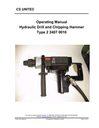
This is the operating manual for CS Unitec Hydraulic Drill and Chipping Hammer Type 2 2407 0010. The manual contains technical specification and operational instruction on using this hydraulic drill and chipping hammer, which has features such as mechanical torque-limiting clutch, no-load hammering absorption, quick-change chuck, SDS max insert tool system and etc.

Recommandé
Contenu connexe
Similaire à CS Unitec Hydraulic Drill and Chipping Hammer Operating Manual
Similaire à CS Unitec Hydraulic Drill and Chipping Hammer Operating Manual (20)
Plus de CS Unitec
Plus de CS Unitec (20)
Dernier
Dernier (20)
CS Unitec Hydraulic Drill and Chipping Hammer Operating Manual
- 1. CS UNITEC Operating Manual Hydraulic Drill and Chipping Hammer Type 2 2407 0010 CS Unitec 22 Harbor Avenue Norwalk, CT 06850 800 700-5919 203 853-9522 Fax 203 853-9921 Website: www.csunitec.com E-mail: info@csunitec.com 2 2407 0010 Manual Erstelldatum 7/28/2004 2:40 PM Page 1 of 15
- 2. 2 2407 0010 Hydraulic Drill and Chipping Hammer CS UNITEC Main features of the tool Mechanical torque-limiting clutch No-load hammering absorption Quick-change chuck SDS max insert tool system Drilling and chiselling modes Chisel position adjustment Gearing and hammering mechanism with grease lubrication Pivotable side handle Depth gauge attachment Technical Specification Operating pressure: 1450 PSI Power: 1.75 HP Speed: 250 RPM Oil flow: 2.6-13.2 GPM Tool system: SDS max Weight (net): appr.28.6 lbs. without hoses Dimensions (L x H x W): 19-1/2“ x 7-1/2“ x 11-3/4” Minimum distance between to the wall: 1-1/2“ Typical drilling perfomance in medium-hard 3/4“ dia.: 14-1/2“/min concrete B 35 1“ dia.: 12“ /min 1-1/4“ dia.: 7-1/2“ /min Noise level : 92 dB (A) Equivalent constant RMS acceleration: 29-1/2 ft./s2 The machine is designed for following uses: use Required insert tools Working Area Drilling in concrete, Drill bit with SDS max. shank Drilling range in cocrete masonry and natural - Hammer drill bits 1/2“-2“ dia. stones - Breach bits 1-9/16“-2“ dia. - Hammer drill bits 1-3/4“-6“ dia. Chiseling in cocrete, Moul pointed, flat and shaped chisels Surface finishing and breaches masonry and natural stone with SDS max. shank Drilling in wood and metal Chuck holder Keyless chuck Wood drill bits and metal drill bits Wood drill bits 3/8“-1-1/4“ dia. with smooth or hex- shank Metal drill bits 3/8-3/4“ dia. Mixing non-flammable Chuck holder materials, e.g. mortar) Keyless chuck Mixing tools with smooth or Mixing tools 3-1/8“-6“ dia. or hex. shank CS Unitec 22 Harbor Avenue Norwalk, CT 06850 800 700-5919 203 853-9522 Fax 203 853-9921 Website: www.csunitec.com E-mail: info@csunitec.com 2 2407 0010 ManualENG Erstelldatum 7/28/2004 2:40 PM Page 2 of 15
- 3. 2 2407 0010 Hydraulic Drill and Chipping Hammer CS UNITEC CS Unitec 22 Harbor Avenue Norwalk, CT 06850 800 700-5919 203 853-9522 Fax 203 853-9921 Website: www.csunitec.com E-mail: info@csunitec.com 2 2407 0010 ManualENG Erstelldatum 7/28/2004 2:40 PM Page 3 of 15
- 4. 2 2407 0010 Hydraulic Drill and Chipping Hammer CS UNITEC CS Unitec 22 Harbor Avenue Norwalk, CT 06850 800 700-5919 203 853-9522 Fax 203 853-9921 Website: www.csunitec.com E-mail: info@csunitec.com 2 2407 0010 ManualENG Erstelldatum 7/28/2004 2:40 PM Page 4 of 15
- 5. 2 2407 0010 Hydraulic Drill and Chipping Hammer CS UNITEC English Deutsch 01 Tool shank Werkzeugschaft 02 Grease Schmierfett 03 Tool Werkzeug 04 Part of SDS max shank Teil des SDS-max Schaftes 05 Front cap Vordere Abdeckung 06 Grip Spannbacke 08 Selector lever Wahlhebel 09 Under cover Untere Abdeckung 10 Stopper Anschlagstange 11 Side handle Seitengriff 12 Taper shank adapter Konusschaftadapter 13 Drill bit (taper shank) Bohren (mit konischem Schaft) Indicating groove shows standard- Anzeigerille zeigt Normalloch- 14 depth matching the outside Tiefe gemäß Außendurchmesser diameter of the anchor for drilling des Ankers für Bohren. 15 Cotter Keil 16 Rest Auflage 17 Drill chuck Bohrfutter 18 Chuck adapter Bohrfutteradapter 19 Core bit Bohrkrone 20 Core bit shank Bohrkronenschenkel 21 Guide plate Führungsplatte 22 Center pin Mittelstift 23 Core bit tip Bohrkronenspitze 24 Crank case cover Kurbelgehäuseabdeckung CS Unitec 22 Harbor Avenue Norwalk, CT 06850 800 700-5919 203 853-9522 Fax 203 853-9921 Website: www.csunitec.com E-mail: info@csunitec.com 2 2407 0010 ManualENG Erstelldatum 7/28/2004 2:40 PM Page 5 of 15
- 6. 2 2407 0010 Hydraulic Drill and Chipping Hammer CS UNITEC GENERAL OPERATIONAL PRECAUTIONS WARNING! When using hydraulic machines, basic safety precautions should always be followed to avoid the risk of personal injury. Read all these instructions before operating this machine and save these instructions. For safe operations: 1. Keep work area clean. Untidy areas and workbenches increase the danger of accidents. 2. Consider work area environment. 3. Keep children away. All visitors should be kept away from work area. 4. Machines not used should be kept safely. They should be stored in a dry, high or locked up place, out of reach of children. 5. Do not force the machine. It will do the job better and safer at the rate for which it was intended. 6. Use the right machine. Do not force small machine or tool to do the job of a heavy duty machine. Do not use tools for purposes not intended. 7. Dress properly. Do not wear loose clothing or jewellery; they can be caught in moving parts. Rubber gloves and non-skid footwear are recommended when working outdoors. Wear protecting hair covering to contain long hair. 8. Use safety glasses. At operations with formation of dust, wear a face or dust mask. 9. Never carry the machine by the hose. 10. Secure work. Use clamps or a vice to fix the work piece. It is safer than using hands and clears boths hand to operate the machine. 11. Do not overreach. Keep proper footing and balance at all times. 12. Maintain tools with care. Keep cutting tools sharp and clean for better and safer performance. Follow instructions for lubrication and changing accessories. Regularly check the hoses and replace in case of damage. Keep handles dry, clean, and free from oil and grease. 13. Disconnect machine. When not in use, before servicing, and when changing accessories such as bits and chisels. 14. Remove adjusting keys and wrenches. Before activating the motor, observe that keys and adjusting wrenches have been removed. 15. Avoid unintentional starting. Do not carry a connected machine with a finger at the button. Before transportation check if the machine is turned off. 16. Stay alert. Watch what you are doing. Use common sense. Do not operate the machine when you are tired. 17. Check damaged parts. Before using the machine, damaged parts or ptitectie devices should be carefully checked to make sutre they work soundly and fulfill the designated function. Check alignment, conections and attachment of moving parts. Also check if parts are broken. Parts or protective devices that are damaged should, if nothing else is mentioned in these operatign instructuions, only be exchanged or repaired by quaified personnel. The same applies to defective switches. Do not use the machine if the switch does not turn it on and off. CS Unitec 22 Harbor Avenue Norwalk, CT 06850 800 700-5919 203 853-9522 Fax 203 853-9921 Website: www.csunitec.com E-mail: info@csunitec.com 2 2407 0010 ManualENG Erstelldatum 7/28/2004 2:40 PM Page 6 of 15
- 7. 2 2407 0010 Hydraulic Drill and Chipping Hammer CS UNITEC 18. Warning The use of other accessories or other additional items than recommended in these operating instructions may include the risk of bodily injury. 19. Have your machine repaired by a qualified personnel. This hydraulic drill and chipping hammer is in accordance with the relevant safety requirements. Repairs should only be carried out by qualified personnel using original spare parts, as otherwise considerable danger may occur for the user. PRECAUTIONS ON USING DRILL AND CHIPPING HAMMER • To protect your ears during operation, wear hearing protection. • Do not touch the bit during or immediately after operation. The bit becomes very hot during operation and could cause serious burns. • Before starting to demolish, chisel or drill into a wall, floor or ceiling, thoroughly confirm that such items as electric cables or conduits are not buried inside. • Always hold the body handle and side handle of the machine firmly. Otherwise the counterforce produced may result in inaccurate and even dangerous operation. CS Unitec 22 Harbor Avenue Norwalk, CT 06850 800 700-5919 203 853-9522 Fax 203 853-9921 Website: www.csunitec.com E-mail: info@csunitec.com 2 2407 0010 ManualENG Erstelldatum 7/28/2004 2:40 PM Page 7 of 15
- 8. 2 2407 0010 Hydraulic Drill and Chipping Hammer CS UNITEC APPLICATIONS • Drilling holes in concrete • Drilling anchor holes • Demolishing concrete, chiselling, digging, and squaring (by applying optional accessories) Deviance of illustration possible CS Unitec 22 Harbor Avenue Norwalk, CT 06850 800 700-5919 203 853-9522 Fax 203 853-9921 Website: www.csunitec.com E-mail: info@csunitec.com 2 2407 0010 ManualENG Erstelldatum 7/28/2004 2:40 PM Page 8 of 15
- 9. 2 2407 0010 Hydraulic Drill and Chipping Hammer CS UNITEC PRIOR TO OPERATION 1. How to install tool NOTE Always use original SPITZNAS tools such as drills or moil pointed chisels. • Clean the toll shank and then lubricate it with the grease provided in the green tube (Fig. 1). • To attach the tool (SDS max shank), insert it into the hole until it contacts the innermost end of the hole as illustrated in Fig. 2. If you continue to turn the tool with slight pressure, you can feel a spot where there is a hitch. At that spot, depress the grip to the direction of an arrow mark and insert the tool all the way until it hits the innermost end. Releasing the grip reverts the grip and secures the tool in place. • To remove the tool, fully depress the grip in the direction of the arrow and pull out the tool. HOW TO USE THE DRILL AND CHIPPING HAMMER 1. How to drill holes (Fig. 4) Pull the switch trigger after applying the drill bit tip to the drilling position. It is unnecessary to forcibly press the machine main body. It is sufficient to slightly press the machine to an extent that shavings are freely discharged. CAUTION Although this machine is equipped with a safety clutch, if the drill bit becomes jammed in concrete or other material, the resultant stoppage of the drill bit could cause the machine body to turn in reaction. Ensure that the main handle and side handle are gripped firmly during operation. 2. How to chisel or demolish (Fig. 5) By applying the tool tip to the chiselling or demolishing position, operate the hammer drill by utilizing its empty weight. Forcible pressing or thrusting is unnecessary. 3. When drilling at “rotation + hammering”: CAUTION: If you switch the selector lever during motor rotation, the tool can start to rotate abruptly, resulting in unexpected accidents. Be sure to switch the selector lever when the motor is at a complete stop. Switching to “rotation + hammering” • Pull the selector lever, release lock and turn it clockwise. • Align ▲ of the selector lever with ▲ on the T side of the undercover as illustrated in Fig. 6. • Push in the selector lever to lock it. NOTE: Turn the selector lever (do not pull it up) to check if it is completely locked and make sure that it does not turn. CS Unitec 22 Harbor Avenue Norwalk, CT 06850 800 700-5919 203 853-9522 Fax 203 853-9921 Website: www.csunitec.com E-mail: info@csunitec.com 2 2407 0010 ManualENG Erstelldatum 7/28/2004 2:40 PM Page 9 of 15
- 10. 2 2407 0010 Hydraulic Drill and Chipping Hammer CS UNITEC 4. When demolishing and chiselling at “hammering”: CAUTION: • If the selector lever is switched during motor rotation, the tool can start to rotate abruptly, resulting in unexpected accidents. Make sure to switch the selector lever when the motor is at a complete stop. • If a chisel or chipper is used at the position of ”rotation + hammering”, the tool can start to rotate, resulting in unexpected accidents. Make sure that they are used at the position of ”hammering”. (1) Switching to ”hammering” • Pull the selector lever, release lock and turn it counter clockwise. • Align ▲ of the selector lever with ▲ on the T side of the undercover as illustrated in Fig. 7. • Push in the selector lever to lock it. NOTE: Turn the selector lever (do not pull it up) to check if it is completely locked and make sure that it does not turn. (2) When fixing working positions of tools such as cold chisel, etc., • Pull the selector lever, release lock and turn it. Align ▲ of the selector lever and T of the undercover as illustrated in Fig. 8. • Push in the selector lever to lock it. • Turn the grip as illustrated in Fig. 9 and fix the tool to the desired working direction. • Turn the selector lever to “striking” according to the procedures mentioned in the above item (1) and secure the position of the tool. 5. Install the stopper (Fig. 10). • Loosen the side handle and insert the straight portion of the stopper into the handle bolt hole. • Move the stopper to the specified position and rotate the grip of the side handle clockwise to fix the stopper. 6. Warming up (Fig. 11). The grease lubrication system in this unit may require warming up in cold regions. Position the end of the bit so makes contact with the concrete, turn on the switch and perform the warming up operation. Make sure that a hitting sound is produced and then use the unit. CAUTION When the warming up operation is performed, hold the side handle and the main body securely with both hands to maintain a secure grip and be careful not to twist your body by the jammed drill bit. CS Unitec 22 Harbor Avenue Norwalk, CT 06850 800 700-5919 203 853-9522 Fax 203 853-9921 Website: www.csunitec.com E-mail: info@csunitec.com 2 2407 0010 ManualENG Erstelldatum 7/28/2004 2:40 PM Page 10 of 15
- 11. 2 2407 0010 Hydraulic Drill and Chipping Hammer CS UNITEC DRILLING AND DRIVING-IN OPERATIONS FOR ANCHORS 1. When a taper shank adapter is used. (Fig. 12) • Install drill bit with taper shank in the taper shank adapter. • Switch on the machine and drill a base hole to the depth sounded by indicating groove on the drill bit. • After cleaning out dust with a bellows, attach the plug to the anchor tip and drive in the anchor with a manual hammer. • To remove the drill bit (taper shank), insert the cotter into the slot of the taper shank adapter and strike the head of the cotter with a manual hammer supporting on rests. (Fig. 13) USING DRILL CHUCK, CHUCK ADAPTER Note that this machine can be used at “rotation only” if separately sold parts such as drill chuck and chuck adapter are attached. Use it with the selector lever positioned at “rotation + hammering”. CAUTION: During operation, be sure to grip the handle and the side handle firmly to prevent your body from swaying. (1) Switching to “rotation + hammering” For switching to “rotation + hammering”, follow the same procedures mentioned in [3. When drilling at “rotation + hammering”]. (2) Attaching chuck adapter to drill chuck (Fig. 14) • Attach the chuck adapter to the drill chuck. • The SDS max shank of the chuck adapter is equivalent to the drill bit. Therefore, follow the same procedures as [How to install tool] for attaching and detaching drill bits. (3) Drilling • Even if you apply more-than-required pressure to the machine body, drilling can never be performed as quickly as you expect. Applying more force or pressure to the machine body than what is needed, on the contrary, damages the drill tip, resulting in the declined working efficiency and shortened life of this machine. • It may sometimes occur that a drill breaks shortly before ending the drilling procedure. Therefore it is important to Diminish the contact pressure, when drilling procedure approaches ist end. HOW TO HANDLE A CORE BIT When a core bit is used, large diameter holes and blind holes can be drilled. In this case, use optional accessories for core bits (such as a center pin and core bit shank) for more efficient operation. 1. Mounting CAUTION Before mounting a core bit, always disconnect the hydraulic hoses. CS Unitec 22 Harbor Avenue Norwalk, CT 06850 800 700-5919 203 853-9522 Fax 203 853-9921 Website: www.csunitec.com E-mail: info@csunitec.com 2 2407 0010 ManualENG Erstelldatum 7/28/2004 2:40 PM Page 11 of 15
- 12. 2 2407 0010 Hydraulic Drill and Chipping Hammer CS UNITEC • Mount the core bit on the core bit shank. (Fig. 15) Before that, feed oil to the screw portion of core bit shank for easy dismounting. • Mount the core bit shank on the main body in the same manner as in mounting the drill bit and the moil pointed chisel. (Fig. 16) • Insert the center pin into the guide plate until it reaches the extremity. • Fit in the guide plate by aligning its concaved portion with the core bit tip. When the position of the concave is shifted by turning the guide plate right or left, the guide plate never slips off even when the drill is used in a downward direction. (Fig. 17) 2. Drilling holes • Disconnect hydraulic hoses • A spring is built in the center pin. By straightly and gently pressing it to the wall or floor surface, the entire surface of the core bit tip attains contact to start the hole drilling job. (Fig. 18) • When the hole depth reaches approximately 5 mm, the hole position can be determined. Then remove the center pin and guide plate from the core bit and continue the hole drilling job. CAUTION When removing the center pin and guide plate, always disconnect the hydraulic hoses. 3. How to dismount the core bit • By holding the machine (with the core bit inserted) in an upward position, drive the machine to repeat impact operation two or three times, whereby the screw is loosened and the drill becomes ready for disassembly. (Fig. 19) • Remove the core bit shank from the machine, hold the core bit with one hand, and strongly strike the head of the SDS max shank portion of the core bit shank with a manual hammer two or three times, whereby the round-head screw is loosened and the drill is ready for disassembly. (Fig. 20) CS Unitec 22 Harbor Avenue Norwalk, CT 06850 800 700-5919 203 853-9522 Fax 203 853-9921 Website: www.csunitec.com E-mail: info@csunitec.com 2 2407 0010 ManualENG Erstelldatum 7/28/2004 2:40 PM Page 12 of 15
- 13. 2 2407 0010 Hydraulic Drill and Chipping Hammer CS UNITEC HOW TO REPLACE GREASE This machine is assembled closely to avoid entrance of dust etc. Therefore, the machine can be used without lubrication for long periodes. Replace the grease as described below. 1. Grease replacement period Replace grease after every 6 months of usage. 2. Grease refilling CAUTION Before refilling the grease, turn the machine off and disconnect the hydraulic hoses. • Remove the crank case cover and wipe off the grease inside (Fig. 21). • Supply 20g of SPITZNAS hammer grease (A) standard accessory contained in a tube) into the crank case. As the tube contains 30g of grease, supply 2/3 of the contained grease. • After refilling the grease, install the crank case cover securely. NOTE The SPITZNAS Hydraulic Hammer Grease A is of the low viscosity type. . MAINTENANCE AND INSPECTION 1. Inspecting the tool Since use of a dull tool will degrade efficiency and cause possible motor malfunction, sharpen or replace the tool as soon as abrasion is noted. Inspecting the mounting screws; Regularly inspect all mounting screws and ensure that they are properly tightened. Should any of the screw be loose, retighten them immediately. Failure to do so could result in serious hazard. CAUTION Repairs, modifications and inspections of SPITZNAS Hydraulic Machines have to be performed only by authorized professionales. NOTE Due to SPITZNAS continuing programme of research and development, the specifications herein are subject to change without prior notice. CS Unitec 22 Harbor Avenue Norwalk, CT 06850 800 700-5919 203 853-9522 Fax 203 853-9921 Website: www.csunitec.com E-mail: info@csunitec.com 2 2407 0010 ManualENG Erstelldatum 7/28/2004 2:40 PM Page 13 of 15
- 14. 2 2407 0010 Hydraulic Drill and Chipping Hammer CS UNITEC Information concerning operating noise and vibration The typical A-weighted sound pressure level: 92 dB(A) (Always wear earplugs to protect your ears during work) The typical weighted root mean square acceleration value: 31 ft./s² CS Unitec 22 Harbor Avenue Norwalk, CT 06850 800 700-5919 203 853-9522 Fax 203 853-9921 Website: www.csunitec.com E-mail: info@csunitec.com 2 2407 0010 ManualENG Erstelldatum 7/28/2004 2:40 PM Page 14 of 15
- 15. 2 2407 0010 Hydraulic Drill and Chipping Hammer CS UNITEC CS Unitec 22 Harbor Avenue Norwalk, CT 06850 800 700-5919 203 853-9522 Fax 203 853-9921 Website: www.csunitec.com E-mail: info@csunitec.com 2 2407 0010 ManualENG Erstelldatum 7/28/2004 2:40 PM Page 15 of 15