Robust and Efficient Coupling of Perception to Actuation with Metric and Non-Metric Representations
•
0 j'aime•571 vues

The talk motivates a re-thinking of the way, how perception passes the information to the control modules. Metric information is not a native space of the camera and apparently also not used in biology for navigation. Early abstraction of information from images loses a lot of important information that can be directly used for following (Visual-Servoing), motion estimation(Motion Blurr), and collision relations(Optical Flow Clustering). I present in this talk ways, how we use the image information in "classical way" that does not require any learning and runs on low-power CPUs.

Recommandé
Recommandé
Contenu connexe
Tendances
Tendances (20)
Similaire à Robust and Efficient Coupling of Perception to Actuation with Metric and Non-Metric Representations
Similaire à Robust and Efficient Coupling of Perception to Actuation with Metric and Non-Metric Representations (20)
Dernier
Dernier (20)
Robust and Efficient Coupling of Perception to Actuation with Metric and Non-Metric Representations
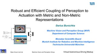
- 1. https://mvp.in.tum.de Machine Vision and Perception Group Virtual Autonomous Driving Meetup Robust and Efficient Coupling of Perception to Actuation with Metric and Non-Metric Representations Darius Burschka Machine Vision and Perception Group (MVP) Department of Computer Science Memeber Scientitfic Board Munich Institute for Robotics and Machine Intelligence Technische Universität München M M
- 2. https://mvp.in.tum.de Machine Vision and Perception Group Virtual Autonomous Driving Meetup MVP Research of the MVP Group, TUM The Machine Vision and Perception Group @TUM works on the aspects of visual perception and control in medical, mobile, and HCI applications Visual navigation Biologically motivated perception Perception for manipulation Visual Action Analysis Photogrammetric monocular reconstruction Rigid and Deformable Registration
- 3. https://mvp.in.tum.de Machine Vision and Perception Group Virtual Autonomous Driving Meetup Research of the MVP Group Exploration of physical object properties Sensor substitution Multimodal Sensor Fusion Development of new Optical Sensors The Machine Vision and Perception Group @TUM works on the aspects of visual perception and control in medical, mobile, and HCI applications
- 4. https://mvp.in.tum.de Machine Vision and Perception Group Virtual Autonomous Driving Meetup 5 Our Experimental Platform (RoboMobil DLR)
- 5. https://mvp.in.tum.de Machine Vision and Perception Group Virtual Autonomous Driving Meetup Coupling Alternatives for Perception Modules M M Sensors Camera,IMU,Laser Structure-from-X Actuators Map-based action planning (not real-time) (Metric Representation) Reactive behavior(Instincts), e.g., Obstacle avoidance,… (real-time for control) do we really need metric representation here?
- 6. https://mvp.in.tum.de Machine Vision and Perception Group Virtual Autonomous Driving Meetup Early Monocular Navigation Approaches VGPS (IROS 2003) 7
- 7. https://mvp.in.tum.de Machine Vision and Perception Group Virtual Autonomous Driving Meetup Problems with camera-based Pose Estimation 8 Camera by itself is too slow with 25- 30Hz to stabilize a robot or monitor high dynamic motion The quality of the reconstructed pose varies with the distance to the observed objects Camera can be blinded for multiple seconds in tunnels, etc.
- 8. https://mvp.in.tum.de Machine Vision and Perception Group Virtual Autonomous Driving Meetup What is different in Robotics compared to Big Data Queries? 9 We need to know not only what is in the area around the robot, but also • How big is the confidence in the correctness of the observation? How much of the object was visible… • How certain is the system to see a specific object (similarity to other similar ones)? • Where it is relative to the robot? • What is the dynamic state of the observed object? • What is the accuracy of the metric observation?
- 9. https://mvp.in.tum.de Machine Vision and Perception Group Virtual Autonomous Driving Meetup Feature Propagation (Data fusion) Strobl, Mair, Bodenmüller, Kielhofer, Sepp, Suppa, Burschka, Hirzinger IROS, IEEE/RSJ, 2009, Best Paper Finalist Mair, Strobl, Bodenmüller, Suppa, Burschka KI, Springer Journal, 2010 linear + gyros based prop.
- 10. https://mvp.in.tum.de Machine Vision and Perception Group Virtual Autonomous Driving Meetup 11 Navigation for Control with 1000Hz from IMU VINS filter design [Schmid et al. IROS 2012] Synchronization of real-time and non realtime modules by sensor hardware trigger Direct system state: High rate calculation by „Strap Down Algorithm“ (SDA) Indirect system state: Estimation by indirect Extended Kalman Filter (EKF)
- 11. https://mvp.in.tum.de Machine Vision and Perception Group Virtual Autonomous Driving Meetup Biology helps with Data Fusion Mair, Burschka Mobile Robots Navigation, book chapter, In-Tech, 2010
- 12. https://mvp.in.tum.de Machine Vision and Perception Group Virtual Autonomous Driving Meetup 13 Can we navigate directly from monocular video with uncertainty information? (Burschka, 2008) Decoupling of rotation and translation allows to put higher weights on intersection errors of long flow vectors Intersection area in the image can be converted into a covariance of the current estimate
- 13. https://mvp.in.tum.de Machine Vision and Perception Group Virtual Autonomous Driving Meetup 70 m trajectory Ground truth by tachymeter 5 s forced vision drop out with translational motion 1 s forced vision drop out with rotational motion Estimation error < 1.2 m (with significant dropouts) Odometry error < 25.9 m Results comparable to runs without vision drop outs VINS-Systems Fusion of heterogeneous data with varying latencies (DLR)
- 14. https://mvp.in.tum.de Machine Vision and Perception Group Virtual Autonomous Driving Meetup 15 Navigation under strong illumination changes • Autonomous indoor/outdoor flight of 60m • Mapping resolution: 0.1m • Leaving through a window • Returning through door
- 15. https://mvp.in.tum.de Machine Vision and Perception Group Virtual Autonomous Driving Meetup Real-Time Navigation Data from an Image Sequence
- 16. https://mvp.in.tum.de Machine Vision and Perception Group Virtual Autonomous Driving Meetup Estimation of the 6 Degrees of Freedom
- 17. https://mvp.in.tum.de Machine Vision and Perception Group Virtual Autonomous Driving Meetup We used to reconstruct static scenes from monocular in 2007… (DLR) Accuracy:1.5cm
- 18. https://mvp.in.tum.de Machine Vision and Perception Group Virtual Autonomous Driving Meetup Mapping to today Modern CUDA GPUs allow 120fps Monocular Navigation from Sparse Optical Flow 19 NVIDIA GPU implementation of sparse flow (feature-based OpenCV) system using only 10% of the resources
- 19. https://mvp.in.tum.de Machine Vision and Perception Group Virtual Autonomous Driving Meetup Autonomous Vehicle Applications – Ultra-Low Power Processing Units: Local Feature Tracking Algorithms (AGAST, fastest keypoint detector part of OpenCV developed by us) (ECCV 2010) •Image-gradient based à Extended KLT (ExtKLT) • patch-based implementation • feature propagation • corner-binding + sub-pixel accuracy • algorithm scales bad with number of features •Tracking-By-Matching à AGAST tracker • AGAST corner detector • efficient descriptor • high frame-rates (hundrets of features in a few milliseconds) + algorithm scales well with number of features • pixel-accuracy 8
- 20. https://mvp.in.tum.de Machine Vision and Perception Group Virtual Autonomous Driving Meetup Rich Information in the Can motion be calculated directly from a single image?
- 21. https://mvp.in.tum.de Machine Vision and Perception Group Virtual Autonomous Driving Meetup What is the underlying principle? (Burschka, IROS 2006) Point Spread Function (PSF) Horizontal motion
- 22. https://mvp.in.tum.de Machine Vision and Perception Group Virtual Autonomous Driving Meetup Motion Blurr (Burschka, IROS 2006) Gaussian window to avoid artifacts in Cepstrum
- 23. https://mvp.in.tum.de Machine Vision and Perception Group Virtual Autonomous Driving Meetup Other non-metric Coupling Alternatives for Perception Modules M M Sensors Camera,IMU,Laser Structure-from-X Actuators Map-based action planning Reactive behavior(Instincts) e.g., Obstacle avoidance,…
- 24. https://mvp.in.tum.de Machine Vision and Perception Group Virtual Autonomous Driving Meetup Navigation Strategies (metric vs. non-metric) Vision-Based Control the control signals are generated directly from the sensor perception Map-based Navigation the reconstructed data is stored in 3D maps to be used for obstacle avoidance and mission planning.
- 25. https://mvp.in.tum.de Machine Vision and Perception Group Virtual Autonomous Driving Meetup 26 is the ratio between the largest and the smallest singular value of the matrix J. The condition number estimates the sensitivity of solu- tion of a linear algebraic system to variations of parame- ters in matrix J and in the measurement vector b. Consider the equation system with perturbations in matrix J and vector b: (J + !δJ )xb = b + !δb (7) The relative error in the solution caused by perturbations of parameters can be estimated by the following inequality using the condition number κ calculated for J (see [5]): ||x − xb|| ||x|| ≤ κ ! ! ||δJ || ||J || + ! ||δb|| ||b|| " + O(!2 ) (8) Therefore, the relative error in solution x can be as large as condition number times the relative error in J and b. The condition number together with the singular values of the matrix J describe the sensitivity of the system to changes in the input parameters. In the following subsections we investigate the observ- ability and accuracy of the output parameters (x, y, z) from the input stream of the camera system (sec. III- A) and the influence of the real sensor on the achievable accuracy of the system (sec. III-B). A. Optimal Landmark Configuration for the Image Jaco- bian Matrix The singular values can be obtained as positive square roots of the eigenvalues of the matrix JT · J. With ∆r, the the value Since space, th the recip 0 0 0 We de placeme expressio ∆r. The dκ dy ⇒ J t i = ∂αi ∂x ∂αi ∂z ∂αi ∂Θ ∂βi ∂x ∂βi ∂z ∂βi ∂Θ = zi x2 i +z2 i − xi x2 i +z2 i −1 − xiyi (x2 i +y2 i +z2 i )· √ x2 i +z2 i − yizi (x2 i +y2 i +z2 i )· √ x2 i +z2 i 0 (2) The dependency on the unknown position (xi, zi) of the robot relative to the tracked landmark can be avoided considering the geometry of the system to: ! x2 i + y2 i + z2 i = yi sin βi , ! x2 i + z2 i = yi tan βi , xi = yi·sin αi tan βi , zi = yi·cos αi tan βi J t i = & tan βi·cos αi yi −tan βi·sin αi yi −1 −sin2 βi·sin αi yi −sin2 βi·cos αi yi 0 ' (3) Note in particular that the Image Jacobian is a function of only one unobserved parameter, yi, the height of the observed point. Furthermore, this value is constant for motion in the plane. Thus, instead of estimating a time- changing quantity as is the case in most vision-based control, we only need to solve a simpler static estimation problem. We refer to [3] for a detailed description of the yi-estimation. J tT (6) tion bot. ons mber mber an orientation ∆Θ relative to it. The equation (3) can then be written in this case as: J t i = 0 −1 −sin2 βi yi 0 = 0 −1 − 1 yi· ( 1+ )ri yi *2 + 0 ri = - x2 i + z2 i (10) From the equation (10) we learn that an error ∆Θ is directly forwarded to the output value αi, while the value ∆wt = (J t )−1 ·∆et , with (J t )−1 = (J tT J t )−1 J tT (6) The value ∆wt describes the error in the 3D position that we use to generate the control signals for the robot. III. SYSTEM ANALYSIS The relative error in the solution caused by perturbations of parameters can be estimated from the condition number of the Image Jacobian matrix J. The condition number is the ratio between the largest and the smallest singular value of the matrix J. The condition number estimates the sensitivity of solu- tion of a linear algebraic system to variations of parame- ters in matrix J and in the measurement vector b. Consider the equation system with perturbations in matrix J and vector b: (J + !δJ )xb = b + !δb (7) The relative error in the solution caused by perturbations of parameters can be estimated by the following inequality using the condition number κ calculated for J (see [5]): ||x − xb|| ||x|| ≤ κ ! ! ||δJ || ||J || + ! ||δb|| ||b|| " + O(!2 ) (8) an orientation ∆Θ relative to it. The equation (3) can then be written in this case as: J t i = 0 −1 −sin2 βi yi 0 = 0 −1 − 1 yi· ( 1+ )ri yi *2 + 0 ri = - x2 i + z2 i (10) From the equation (10) we learn that an error ∆Θ is directly forwarded to the output value αi, while the value ∆r, the error in the distance to the feature, is scaled with the value κr = . y · / 1 + ! ri yi "2 01−1 (11) Since in our case the measurement error is in the image space, the resulting errors in the world are dependent on the reciprocal values. 0.15 0.2 0.25 0.3 κr Consider the equation system with perturbations in matrix J and vector b: (J + !δJ )xb = b + !δb (7) The relative error in the solution caused by perturbations of parameters can be estimated by the following inequality using the condition number κ calculated for J (see [5]): ||x − xb|| ||x|| ≤ κ ! ! ||δJ || ||J || + ! ||δb|| ||b|| " + O(!2 ) (8) Therefore, the relative error in solution x can be as large as condition number times the relative error in J and b. The condition number together with the singular values of the matrix J describe the sensitivity of the system to changes in the input parameters. In the following subsections we investigate the observ- ability and accuracy of the output parameters (x, y, z) from the input stream of the camera system (sec. III- A) and the influence of the real sensor on the achievable accuracy of the system (sec. III-B). A. Optimal Landmark Configuration for the Image Jaco- bian Matrix The singular values can be obtained as positive square roots of the eigenvalues of the matrix JT · J. With yi∈{1,...,N} as heights of the tracked objects, αi∈{1,...,N} as azimuth angles to them and βi∈{1,...,N} as their eleva- tion angles. The resulting matrix for N landmarks has the form shown in (9). The system estimates three parameters (dx, dy, dΘ) from the image positions (ui, vi) of all tracked primitives Since in our case the measurement error is in the image space, the resulting errors in the world are dependent on the reciprocal values. 0 2 4 6 8 10 12 14 16 18 20 0.05 0.1 0.15 0.2 0.25 0.3 y κr r Fig. 3. Dependency of κr on yi and ri. We deduce from the above equation that the optimum placement of the feature should maximize the above expression to allow good observability of the position error ∆r. The optimal value can be estimated to dκr dyi = − 1 xi 2 ( 1 + ri 2 yi 2 + + 2 · ri 2 yi 4 ( 1 + ri 2 yi 2 +2 = 0 ⇒ yi = ±ri ⇒ βi = arctan yi ri (12) that corresponds to an angle |βi| = 45◦ . It is shown that any linear system has at least one solution component whose sensitivity to perturbations is proportional to the condition number of the matrix, but there may exist many components that are much better Optimal Feature Selection (Burschka ICRA 2003)
- 26. https://mvp.in.tum.de Machine Vision and Perception Group Virtual Autonomous Driving Meetup Capturing Motion Properties of Large Dynamic Scenes Cars in distances over 50m are only a few pixels large. Metric reconstruction is very uncertain due to small disparity values with large noise levels in estimation ⇒ Metric Estimation of the dynamic state is impossible d p = B⋅ f px ⋅ 1 z pixel [ ]
- 27. https://mvp.in.tum.de Machine Vision and Perception Group Virtual Autonomous Driving Meetup Direct Mapping of Point Motion on Image Observation (BMVC 2017)
- 28. https://mvp.in.tum.de Machine Vision and Perception Group Virtual Autonomous Driving Meetup Detection of Independent Motion Groups from Optical Flow • Our goal is a robust detection of motion direction and collision times from a monocular uncali- brated camera sequence. • Representation of the dynamic scene ordered by collision times instead of Cartesian coordinates aenables monocular processing (no scale neces- sary) and better priorisation of collision candidates than in conventional methods • Independent estimation of motion direction and collision time allows collision categorization in large distances from the camera Schaub et al., Journal ITSC 2017 Burschka, BMVC 2017 t=0 t=1 t=2 k vgi Vgi PI Ei PI Vgi H H H
- 29. https://mvp.in.tum.de Machine Vision and Perception Group Virtual Autonomous Driving Meetup Obstacle Avoidance in Dynamic Spaces 30
- 30. https://mvp.in.tum.de Machine Vision and Perception Group Virtual Autonomous Driving Meetup 31 Novel Control Design for Non-metric Control from Monocular (Transactions on ITS 2016 Schaub&Burschka) • Matlab simulation with 3 objects (C is on collision course) • Non-Linear Gradient- Descent with an Adaptive Lagrange Interpolation Search (ALIS) • Weights: Results: Optimization DLR.de • Chart 10 > ICSTCC15 > Alexander Schaub • Reactive Avoidance of Dynamic Obstacles through Optimization of their Epipoles > 14.10.15 Δ"↓. • Good performance: 2 Steps to reach the optimum • Realtime implementation with 25 Hz Δ"↓- • Planning space represented as collision times for different velocities New Controller is necessary for the non- metric input:
- 31. https://mvp.in.tum.de Machine Vision and Perception Group Virtual Autonomous Driving Meetup Navigation based on Pixel-Information from Monocular View Concept: Shifting the optical flow epipole out of the object’s boundaries à no collision Planar motion of the objects (P ∈ ℝ!{𝑋, 𝑌, 𝑍 = 𝑐}) Effect of the relative velocity 𝑣 = {𝑣", 𝑣#} on the Epipole’s 2D image position (𝑥, 𝑦) à find: Δ𝐸$ = f(Δ𝑣", Δ𝑣#) : Schaub, Burschka ITSCC 2015
- 32. https://mvp.in.tum.de Machine Vision and Perception Group Virtual Autonomous Driving Meetup Novel Non-Cartesian Map Structure (IROS 2019) 33 Map is indexed by the azimuth angle of the relative velocity vector and the time until the plane with the velocity vector as a normal passes the focal point TTC This makes the map content static in dynamic environments. Merely a TTC counter scrolls the grid during the operation but no changes of the grid information is necessary! lations and epipolar analysis of optical flow in the image sequence [1]. object in a metric sense does not necessarily pose any problems on the obstacle avoidance. Fig. 2 Geometric indexing to the scene representation may result in incorrect pr objects for dynamic analysis. Another reason requiring a modification in the task representation is sensing accuracy. While the sensors can cope correctly with the 3D info typical indoor environment, the signal-to-noise ratio makes any 3D recon large scale environments useless. The error due to detection and matchi of the stereo system is larger than the displacement information between images used for reconstruction. A dynamic state estimation from chang position of vehicles becomes unreliable (Fig. 3). It is apparent that the
- 33. https://mvp.in.tum.de Machine Vision and Perception Group Virtual Autonomous Driving Meetup Identification of Interaction Regions in the Scene 34 Kitani et al. [26] infer future long-term walking paths from the physical world with obstacles and preferred areas as sidewalks but do not analyze temporal evolution after initial estimation like this approach. Fig. 2. Map data is enriched by interaction regions(orange) caused by static POI (entrances to shops, narrows) (green), dynamic intersection regions (blue) based on intersecting trajectories. Pictured area of second example. III. APPROACH Our approach is divided into three parts: First, a static map of Points and Areas of Interest (POI/AOI) is computed offline beforehand (Figure 2), which is used for local Extraction of map-based POI static Pedestrian Intention Detection as a Resource Competition Challenge Peter Gawronski1 Darius Burschka2 Abstract— We propose an approach to classify possible in- teraction types between autonomous vehicles and pedestrians based on the idea of resource competition in shared spaces. Autonomous vehicles are more challenged in urban traffic scenarios as lots of uncertainties influence the current world model. Urban environments impose very little constraints on the motion of pedestrians. This creates the demand for an approach to determine intentions for each pedestrian as far ahead as possible and to react to changes early. A motion model based on goal-driven pedestrian movement shows a set of most likely planned trajectories. These are analyzed for overlapping occupation times in road segments, thus interactions with the vehicle. The output is an early estimation which suggests most probable interaction types and places. From this estimation, current trajectory of the pedestrian is used to refine the prediction of the most probable intention of interaction place and type. In the end the algorithm combines topological and behavioral input to infer and validate long term intention Fig. 1. Person starting to run towards an intersection: Changes in behavior indicate a change of mind and thus a new interaction type. Highlighted interaction area based on the temporal resource competition analysis. Scenario 3, cutout of frame 19997 3. Very similar behavior can have different causes and outcomes, as pedestrian movement is not limited very much, thus changes in trajectory and intention happen very quickly. CONFIDENTIAL. Limited circulation. For review only. Identification of overlapping ”resource” allocation (competition for POI) dynamic
- 34. https://mvp.in.tum.de Machine Vision and Perception Group Virtual Autonomous Driving Meetup Estimation of Intention of the Traffic Agents 35 which interactions between motorists will occur most likely, but is feasible for pedestrian movement as to determine movement across the road. Furthermore, static infrastructure can be plotted into the database such as crosswalks, sig- nalized crossings or narrow passages in low density urban areas. It is merged with destinations of travel in the scene as crossroads to another street, entries to parking lots shops or areas of shared space, e.g. a pedestrian headed towards a crosswalk. a) Influences of topology: Figure 3 shows some typical topologies and how they influence behavior. In all scenarios, the hypothetical arrival and occupation time is calculated for the pedestrian as depicted on the left. The vehicle is limited to the road, but may change lanes or turn. A long term goal may influence behavior and trajectory of a pedestrian, as different paths lead to the same goal and non-interference with cars may be intended. Third example includes crosswalk and thus creates a strong goal as crossing is safer there and makes jaywalking less probably. The last example shows a possible situation at a corner. Arrival time of the pedestrian is identical for both crossings, an interaction with the vehicle depending on the unknown goal. Temporal analysis is needed to evaluate further. taneous usage is not possible, shown in Figure 1 in red. This limitation is used for behavior prediction as some form of reaction is needed to avoid a collision, either by change of velocity or direction by one or more of the participants involved. A planned solution may exist, as with right-of- way, but changes in behavior may solve these differently than anticipated, e.g. the yielding object accelerating to avoid the yield situation, as in scenario 3. Fig. 4. Schematic behavior patterns in a interaction scenario: 1/2: vehicle passing behind/in front of the pedestrian from a collision situation, 3: passive pedestrian; 4: assertive crossing; 5/6/7: changes in velocity which may influence outcome, 8/9: pedestrian turning away/towards the road as indicators against/for crossing intention. Details in chapter III-C . C. Temporal Analysis of Behavior A temporal analysis is performed to analyze the behavior Temporal evolution of TTC at the resource allows to assess passivity of aggressivity of the traffic partner includes crosswalk and thus creates a strong goal as crossing is safer there and makes jaywalking less probably. The last example shows a possible situation at a corner. Arrival time of the pedestrian is identical for both crossings, an interaction with the vehicle depending on the unknown goal. Temporal analysis is needed to evaluate further. Fig. 3. Schematic overview of influences of POI to pedestrian movement: Possible walking paths for a pedestrian (orange) and the ego vehicle (purple) and found POI in range (green). LTR: no POI in area; possible paths to cross the road; introducing crosswalks/right of way; different options create different situations b) Occupation times: To compensate for input noise and the fact that the whole area must be cleared of obstruc- tions before safe passage is possible, some buffer around Fig. 4. Schematic behavior patterns in a interaction scenario: 1/2: vehicle passing behind/in front of the pedestrian from a collision situation, 3: passive pedestrian; 4: assertive crossing; 5/6/7: changes in velocity which may influence outcome, 8/9: pedestrian turning away/towards the road as indicators against/for crossing intention. Details in chapter III-C . C. Temporal Analysis of Behavior A temporal analysis is performed to analyze the behavior and predict which of previously estimated probable actions is performed. Both objects involved use nonverbal commu- nication in form of clear changes in TTA by changes in velocity and/or direction to clear an interfering situation. Pedestrians may give visual clues to a driver [11], but as these are not always clear, especially in-camera due to low resolution, and also they can go unnoticed or misinterpreted by an algorithmic detector, they are not taken into account in this work. In situations of clear legislation, the expected output is anticipated. Unexpected behavior can have multiple causes by means of aggressiveness or situation awareness, but can also be a sign of distraction from the situation. Open situations can have several outcomes, so the analysis of Static and dynamic POI allow a better prediction of intentions Changes in the temporal interaction with agents can be used for behavior analysis (IV 2019)
- 35. https://mvp.in.tum.de Machine Vision and Perception Group Virtual Autonomous Driving Meetup Conclusions • Non-metric navigation allows operations directly in camera images without the necessity of metric scale • Temporal representation helps to assess and predict behaviors • Learning approaches are based on similarity search and, therefore, built for segmentation and labeling – not for metric measurements • Scene understanding from single images reconstruct only spatial but no temporal relations • Early data abstraction loses often important information from the sensor • Driving can be modelled as resource competition on the road
- 36. https://mvp.in.tum.de Machine Vision and Perception Group Virtual Autonomous Driving Meetup Questions?