
Recommandé
Recommandé
Contenu connexe
En vedette
En vedette (15)
Similaire à 2000tundrars3200install
Similaire à 2000tundrars3200install (20)
Dernier
Dernier (20)
2000tundrars3200install
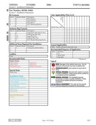
- 1. Page 1 of 22 PagesRev.: C 01/25/00 PPO TOYOTA TUNDRA 2000 - TVIP V3 (RS3000) Section I - Installation Preparation Part Number: 08586-34861 Section I - Installation Preparation Kit Contents Item # Quantity Reqd. Description 1 1 Wire Harness 2 1 Status Monitor 3 1 Piezo Buzzer 4 1 ECU Mounting Bracket Hardware Bag Contents Item # Quantity Reqd. Description 1 3 Large Foam Tape Strip (2 pcs.) 2 1 Small Foam Tape Strip 3 10 Large Wire Ties 4 15 3 Medium Wire Ties ECU Bracket Mounting Screws5 6 Additional Items Required For Installation Item # Quantity Reqd. Description 1 1 V3 Base Kit (08585-00921) 2 3 Conflicts Note: Recommended Tools Safety Tools Safety Glasses (Optional) Safety Gloves (Optional) Vehicle Protection Blankets, Part Boxes Special Tools Striker Tool Installation Tools Phillips Head Screwdrivers #1 and #2, screwdrivers or tips Small, Flat Blade Screwdriver 10 mm Socket Pneumatic/Electric Wrench Torque Wrench Nylon Panel Removal Tool Side Cutters Utility Knife Windex Special Chemicals Color Applicability/Trim Level Accessory Color Vehicle/Trim Color General Applicability 2000 - Tundra with power door locks, only. Recommended Sequence of Application Item # Accessory 1 V3 2 Wood Dash 3 Fog Lights *Mandatory Legend STOP STOP: Damage to the vehicle may occur. Do not proceed until process has been complied with. OPERATOR SAFETY: Use caution to avoid risk of injury. CRITICAL PROCESS: Proceed with caution to ensure a quality installation. These points will be audited on a completed vehicle installation. GENERAL PROCESS: This highlights specific processes to ensure a quality installation. These points will be audited during the accessory installation. TOOLS & EQUIPMENT: This calls out the specific tools and equipment required for this process.
- 2. TOYOTA TUNDRA 2000 - TVIP V3 (RS3000) Section II - Installation Procedure Page 2 of 22 PagesRev.: C 01/25/00 PPO Fig. A1 Fig. A3 Fig. A4 4. Remove the hood release lever. (Fig. A4) i. Remove the two screws securing the hood release lever. 5. Remove the lower dash cover. (Fig. A4) i. Remove the four bolts securing the lower dash cover. ii. Do not scratch the cover. 2. Remove the driver’s step cover. (Fig. A2) i. Remove the four or five screws securing the cover. ii. Do not scratch the cover. iii. Do not break the alignment clips when reinstalling the step cover; align them with the holes before pressing the step cover down. 3. Remove the driver’s cowl cover. (Fig. A3) i. Remove the nut securing the cover. ii. Protect the floor and seat before proceeding. iii. Do not scratch the cover. A. Vehicle Disassembly 1. Remove the negative battery cable (Fig. A1) i. Protect the fender before starting. ii. Be careful to not touch the positive terminal. Battery Negative – Cable 10 mm Socket Screw (x4–X-tra Cab, x5–Regular Cab) Step Cover Phillips Head Screwdriver Fig. A2 Cowl Cover Nut Bolt (x2) Bolt (x2) Screw (x2) Lower Dash Cover Phillips Head Screwdriver,10 mm Socket Hood Release Lever
- 3. TOYOTA TUNDRA 2000 - TVIP V3 (RS3000) Section II - Installation Procedure Page 3 of 22 PagesRev.: C 01/25/00 PPO Fig. A5 Fig. A6 7. Remove the center heater duct. (Fig. A6) 6. Remove the left cluster panel. (Fig. A5) i. Disconnect any connectors. ii. Do not scratch the panel. Left Cluster Panel Nylon Removal Tool Center Heater Duct
- 4. Page 4 of 22 PagesRev.: C 01/25/00 TOYOTA TUNDRA 2000 - TVIP V3 (RS3000) Section II - Installation Procedure PPO Fig. B1 Fig. B2 Fig. B3 3. Using two large strips of foam tape, cover the edges of the V3 ECU and ECU mounting bracket as shown. (Fig. B3) i. Cover the edge of V3 ECU and mounting bracket where the connectors come out, and the side opposite the ECU connectors. 2. Using two large strips of foam tape, cover the edge of the V3 ECU and mounting bracket opposite the ECU connectors as shown. (Fig. B2) i. Wrap the foam tape around the edge and on to the top surface of the ECU. B. V3 ECU Preparation and Installation 1. Using the three provided screws, attach the ECU mounting bracket to the back of the V3 ECU as shown. (Fig. B1) i. Lay the V3 ECU face down with the connectors facing the right. ii. Lay the bracket on top of the ECU as shown, with the tab on the right and the lip of the bracket covering the edge of the ECU. Connectors ECU Mounting BracketV3 ECU Screw (x3) #1 Phillips Screwdriver Large Foam Tape Strip (x2) ECU Mounting Bracket V3 ECU Connectors ECU Mounting Bracket V3 ECU Large Foam Tape Strip (x2)
- 5. Page 5 of 22 PagesRev.: C 01/25/00 TOYOTA TUNDRA 2000 - TVIP V3 (RS3000) Section II - Installation Procedure PPO Fig. B4 Fig. B5 5. Cut or tear one large strip of foam tape in half. (Fig. B5) 4. Using a small strip of foam tape, wrap the edge of the mounting bracket’s tab as shown. (Fig. B4) ECU Mounting Bracket Small Foam Tape Strip Large Foam Tape Strip CUT or TEAR 6. Remove the connector block mounted against the fire wall to the right side of the steering column. (Fig. B6) i. Remove the nut securing the connector block. 7. Using a ¹⁄₂ strip of foam tape, cover the edge of the indicated metal bracket near the steering column. (Fig. B6) Fig. B6Connector Block Steering Column Nut Bracket Foam Tape (¹⁄₂ Strip) 10 mm Socket Utility Knife or Scissors
- 6. Page 6 of 22 PagesRev.: C 01/25/00 TOYOTA TUNDRA 2000 - TVIP V3 (RS3000) Section II - Installation Procedure PPO Fig. B7 Fig. B8 9. With the connectors facing left, slide the ECU mounting bracket over the existing stud bolt, then secure it and connector block with the previously removed nut. (Fig. B8) i. Verify the nut is tightened securely. 8. Connect the V3 harness’ ECU connectors (10P, 10P, 4P) to the V3 ECU. (Fig. B7) i. Verify the connectors are plugged into the ECU securely. V3 ECU V3 Harness Connector Block Nut (existing) 10 mm Socket ECU Mounting Bracket V3 Harness’ ECU Connectors (10P, 10P, 4P)
- 7. Page 7 of 22 PagesRev.: C 01/25/00 TOYOTA TUNDRA 2000 - TVIP V3 (RS3000) Section II - Installation Procedure PPO Fig. C1 Fig. C2 10 5 15 5 10 5 5 10 15 20 5 5 20 15 Fig. C3 4. Disconnect the vehicle harness’ 16P and 7P connectors from the Driver Side J/B. (Fig. C3) i. Do not pull on the wires; pull on the connectors. 2. Plug the V3 harness’ 2P female (terminals) connector into the vehicle’s 2P connector. (Fig. C2) i. Verify the connector is plugged in securely. 3. Route the V3 harness up toward the Driver Side J/B and secure it to the vehicle’s harness with three medium wire ties. (Fig. C2) i. Route and secure the V3 harness so that it does not touch the metal bracket. ii. Clip the wire ties. C. V3 Harness and GBS ECU Installation 1. Locate the vehicle harness’ 2P connector on top of the connector junction block in the driver’s cowl area. (Fig. C1) 2P Connector Junction Block 2P Medium Wire Tie (x2) Vehicle Harness V3 Harness Medium Wire Tie Metal Bracket Pliers 7P Driver Side J/B 16P
- 8. Page 8 of 22 PagesRev.: C 01/25/00 TOYOTA TUNDRA 2000 - TVIP V3 (RS3000) Section II - Installation Procedure PPO 10 5 15 5 10 5 5 10 15 20 5 5 20 15 Fig. C4 Fig. C5 10 10 10 15 20 10 10 20 10 20 10 15 15 Fig. C6 7. Plug in the V3 harness’ 7P connectors between the vehicle harness’ 7P connector and the Driver Side J/B. (Fig. C6) i. Verify the connectors are plugged in securely. 8. Route the V3 harness toward the steering column, then secure it and the 7P connectors to the vehicle’s harness. (Fig. C6) i. Secure the connectors with one large wire tie, and the V3 harness with one medium wire tie. ii. Clip the wire ties. 6. Secure the 16P connectors and the V3 harness to the vehicle’s harness as shown. (Fig. C5) i. Secure the connectors in front of the Driver Side J/B as shown with one large wire tie. ii. Secure the V3 harness next to the Driver Side J/B as shown with one medium wire tie. iii. Clip the wire ties. 5. Plug in the V3 harness’ 16P connectors between the vehicle harness’ 16P connector and the Driver Side J/B. (Fig. C4) i. Verify the connectors are plugged in securely. Driver Side J/B 16P 16P Side Cutters Driver Side J/B Vehicle’s Harness Medium Wire Tie 16P Side Cutters Driver Side J/B V3 Harness Vehicle’s Harness Medium Wire Tie Large Wire Tie 7P Large Wire Tie
- 9. Page 9 of 22 PagesRev.: C 01/25/00 TOYOTA TUNDRA 2000 - TVIP V3 (RS3000) Section II - Installation Procedure PPO Fig. C7 Fig. C8 LOC K ACC ON S TART Fig. C9 10. Plug in the V3 harness’ 8P connectors between the vehicle harness’ 8P connector and the ignition switch. (Fig. C8) i. Verify the connectors are plugged in securely. 11. Secure the 8P connectors and the V3 harness to the vehicle’s harness. (Fig. C8) i. Secure the connectors with one large wire tie as shown so the lower dash cover can be reinstalled without touching the connectors. ii. Secure the V3 harness to the vehicle’s harness with three medium wire ties. iii. Clip the wire ties. 12. Using one large wire tie, secure the GRAY Antenna wire to the ignition switch cylinder, then cut off the excess. (Fig. C9) i. Pull the wire tie tight so that the GRAY wire will not slip out. ii. Cut the GRAY wire only after tightening the wire tie. iii. Clip the wire tie. 9. Disconnect the vehicle harness’ 8P connector from the ignition switch. (Fig. C7) i. Do not pull on the wires; pull on the connector. 8P Side Cutters V3 Harness Vehicle’s Harness Medium Wire Tie (x3) Large Wire Tie GRAY Antenna Wire 8P Side Cutters Large Wire Tie CUT! GRAY Antenna Wire
- 10. Page 10 of 22 PagesRev.: C 01/25/00 TOYOTA TUNDRA 2000 - TVIP V3 (RS3000) Section II - Installation Procedure PPO Fig. C10 Fig. C11 Fig. C12 17. Secure the GBS ECU to the support brace with the adjustment screw facing you. (Fig. C12) i. Secure the GBS ECU as shown and do not overtighten the wire ties. ii. Clip the wire ties. Caution: Be sure the GBS ECU is positioned clear of the heater duct opening. 15. Plug in the V3 harness’ clear 6P connector into the GBS ECU. (Fig. C11) i. Verify the connector is plugged in securely. 16. Locate the support brace above the Driver Side J/B. (Fig. C11) 13. Turn the adjustment screw on the GBS ECU to the 4 position. (Fig. C10) i. Adjust as necessary during the system function check. 14. Insert two large wire ties through the holes on the back of the GBS ECU. (Fig. C10) Small Flat Blade Screwdriver GBS ECU GBS ECU Setting Large Wire Tie (x2) GBS ECU V3 Harness Support Brace Driver Side J/B 6P (Clear) Side Cutters Large Wire Tie (x2) Support Brace GBS ECU
- 11. Page 11 of 22 PagesRev.: C 01/25/00 TOYOTA TUNDRA 2000 - TVIP V3 (RS3000) Section II - Installation Procedure PPO Fig. D1 Fig. D2 Fig. D3 3. Connect the V3 harness’ clear and blue 2P connectors to the Status Monitor’s clear and blue 2P connectors. (Fig. D3) i. Verify the connectors are plugged in securely. 4. Using the remaining ¹⁄₂ strip of foam tape, wrap the 2P connectors together. (Fig. D3) 5. Reinstall the left cluster panel. (Fig. D3) i. Reconnect any vehicle harness’ connectors (for the dimmer control, etc.) and verify they are plugged in securely before installing the panel. 2. Insert the Status Monitor into the left cluster panel’s knockout opening. (Fig. D2) i. Do not scratch the panel. D. Status Monitor Installation 1. Remove the knockout cover from the left cluster panel. (Fig. D1) i. Do not scratch the panel. Knockout Cover Left Cluster Panel Status Monitor Left Cluster Panel 2P (Blue) Foam Tape (¹⁄₂ Strip) 2P (Clear)
- 12. Page 12 of 22 PagesRev.: C 01/25/00 TOYOTA TUNDRA 2000 - TVIP V3 (RS3000) Section II - Installation Procedure PPO Fig. E1 Fig. E2 Fig. F1 2. Plug the piezo buzzer’s gray 2P connector into the vehicle harness’ gray 2P connector. (Fig. E2) i. Verify the connector is plugged in securely. 3. Secure the piezo buzzer to the vehicle’s harness with one large strip of foam tape and one large wire tie, then secure its harness to the vehicle’s harness with one medium wire tie. (Fig. E2) i. Secure the buzzer with the hole pointing down. ii. Clip the wire ties. F. Warning Label Installation 1. Clean the inside surface on the front door windows. (Fig. F1) 2. Attach the warning labels to the inside surface of the door windows as shown. (Fig. F1) i. Use a piece of adhesive tape to remove the labels from their protective backing sheets. ii. Hold the adhesive tape to align the labels properly. iii. Verify there are no visual defects (bubbles, fingerprints, etc.) E. Piezo Buzzer Installation 1. Locate the vehicle harness’ gray 2P connector in the back corner on the driver’s side of the engine compartment. (Fig. E1) i. Remove and discard the protective cap. 2P (Gray) Cap (Remove) Side Cutters Hole Points Down Vehicle Harness Medium Wire Tie Large Wire Tie Vehicle Harness Foam Tape Piezo 2P (Gray) Warning Label 10 mm Window Etching Level With Trim, Parallel To Bottom Edge of Window Etching
- 13. Page 13 of 22 PagesRev.: C 01/25/00 TOYOTA TUNDRA 2000 - TVIP V3 (RS3000) Section II - Installation Procedure PPO Fig. G1 G. Completing the Installation 1. Complete the reassembly of the vehicle. i. Verify the panels fit properly with no uneven gaps between panels. 2. Clean up any trash. 3. Reconnect the negative battery cable. (Fig. G1) i. Attach the battery cable at a 45º angle as shown. ii. Tighten the nut to 3 ft.•lbs. torque. iii. Do not touch the positive terminal. 4. Place the remote controls, owner’s guide and insurance card, left in their bags, in the glove box. Battery Negative – Cable 45˚ Torque Wrench, 10mm Socket
- 14. Page 14 of 22 Pages Section III - Functional Verifications Rev.: C 01/25/00 □ □ □ □ □ □ Check: Press and release the remote’s top button to arm the system. Press and release the remote’s top button again to disarm the system. Open and close the driver’s door. Arm and disarm the system with the remote again, then wait thirty seconds. Press and release the remote’s top button again to disarm the system. Open the driver’s door, then press and release the remote’s top button. Close the driver’s door. Press and hold the remote’s top button for more than two seconds. Look for: The tail and marker lights flash once. The Piezo chirps once. The interior lights turn on for three seconds. Both doors lock. The Status Monitor’s LED starts flashing. The tail and marker lights flash twice. The Piezo chirps twice. The interior lights turn on for thirty seconds. Both doors unlock. The Status Monitor’s LED stops flashing. The tail and marker lights flash once. The Piezo chirps once. The interior lights turn on for three seconds. Both doors lock. The Status Monitor’s LED starts flashing. The tail and marker lights flash twice. The Piezo chirps twice. The interior lights turn on for thirty seconds. Both doors unlock. The Status Monitor’s LED stops flashing. The Piezo sounds continuously. The Piezo stops sounding. The doors lock, then unlock. The Piezo chirps once (when the doors lock), then twice (when the doors unlock.) The horn sounds in a unique pattern. The interior lights flash in the same pattern. The tail and marker lights flash in the same pattern. The Status Monitor’s LED flashes in the same pattern. TOYOTA TUNDRA 2000 - TVIP V3 (RS3000) Section III - Functional Verifications PPO
- 15. Page 15 of 22 Pages Section III - Functional Verifications Rev.: C 01/25/00 □ □ □ □ □ □ □ □ Check: Press and release the remote’s top button. Sit in the driver’s seat and make sure both doors are closed. Insert the key into the ignition switch and turn it to “ON”. Turn the key back to “ACC”. Turn the key to “ON”, roll down both windows, turn the key back to “LOCK”, then remove it and exit the vehicle. Press and release the remote’s top button to arm the system. Reach inside, unlock and open driver’s door, then sit in the driver’s seat. (If checking a M/T vehicle, fully depress the clutch pedal for the next step.) Insert the key into the ignition switch and turn it to “START”. Turn the key back to “ACC”, then to “START” again. Turn the key back to “LOCK”, remove it, exit the vehicle, then check the front pas- senger door without performing the starter cut check. Look for: The horn stops sounding. All the lights stop flashing. The Piezo chirps twice. Both doors lock. Both doors unlock. The tail and marker lights flash once. The Piezo chirps once. The interior lights turn on for three seconds. Both doors lock. The Status Monitor’s LED starts flashing. The horn sounds in a unique pattern. The interior lights flash in the same pattern. The tail and marker lights flash in the same pattern. The Status Monitor’s LED flashes in the same pattern. The engine does not start (no cranking). The horn stops sounding. All the lights stop flashing. The Status Monitor’s LED stops flashing. The starter cranks and the engine starts. Same as before. TOYOTA TUNDRA 2000 - TVIP V3 (RS3000) Section III - Functional Verifications PPO
- 16. Page 16 of 22 Pages Section III - Functional Verifications Rev.: C 01/25/00 □ □ □ □ Check: Roll up both windows, remove the key and exit the vehicle. Press and release the remote’s top button to arm the system. Pull the plunger on the striker tool ¹⁄₃ to ¹⁄₂ way out, then release it to strike the center of the driver’s door window. Pull the plunger all the way out to tap the center of the driver’s door window again. Disarm the system with the remote. Look for: The tail and marker lights flash once. The Piezo chirps once. The interior lights turn on for three seconds. Both doors lock. The Status Monitor’s LED starts flashing. The alarm should not be triggered. The horn starts sounding. The tail and marker lights starts flashing. Note: If you do not disarm the system with the remote control, the horn will sound and the lights will flash for 20 seconds. It is not necessary to check the alarm duration. The horn stops sounding. All the lights stop flashing. The Status Monitor’s LED stops flashing. TOYOTA TUNDRA 2000 - TVIP V3 (RS3000) Section III - Functional Verifications PPO
- 17. A. Vehicle Disassembly 1. Remove the negative battery cable (Fig. A1) i. Protect the fender before starting. ii. Be careful to not touch the positive terminal. 2. Remove the driver’s step cover. (Fig. A2) ii. Do not scratch the cover. iii. Do not break the alignment clips when reinstalling the step cover; align them with the holes before pressing the step cover down. 3. Remove the driver’s cowl cover. (Fig. A3) ii. Protect the floor and seat before proceeding. iii. Do not scratch the cover. 4. Remove the hood release lever. (Fig. A4) 5. Remove the lower dash cover. (Fig. A4) ii. Do not scratch the cover. 6. Remove the left cluster panel. (Fig. A5) ii. Do not scratch the panel. 7. Remove the center heater duct. (Fig. A6) B. V3 ECU Preparation and Installation 1. Using the three provided screws, attach the ECU mounting bracket to the back of the V3 ECU as shown. (Fig. B1) 2. Using two large strips of foam tape, cover the edge of the V3 ECU and mounting bracket opposite the ECU connectors as shown. (Fig. B2) i. Wrap the foam tape around the edge and on to the top surface of the ECU. Page 17 of 22 Pages Part Number: 08586-34861 Rev.: C 01/25/00 TOYOTA TUNDRA 2000 - TVIP V3 (RS3000) Section IV - Installation Process/Audit Criteria PPO Section IV: Process/Audit Criteria Process Audit Audited during accessory installation Audited on completed vehicle installation Paragraph numbers refer to paragraph numbers in Section II
- 18. 3. Using two large strips of foam tape, cover the edges of the V3 ECU and ECU mounting bracket as shown. (Fig. B3) i. Cover the edge of V3 ECU and mounting bracket where the connectors come out, and the side opposite the ECU connectors. 4. Using a small strip of foam tape, wrap the edge of the mounting bracket’s tab as shown. (Fig. B4) 5. Cut or tear one large strip of foam tape in half. (Fig. B5) 6. Remove the connector block mounted against the fire wall to the right side of the steering column. (Fig. B6) 7. Using a ¹⁄₂ strip of foam tape, cover the edge of the indicated metal bracket near the steering column. (Fig. B6) 8. Connect the V3 harness ECU connectors (10P, 10P, 4P) to the V3 ECU. (Fig. B7) i. Verify the connectors are plugged into the ECU securely. 9. With the connectors facing left, slide the ECU mounting bracket over the existing stud bolt, then secure it and connector block with the previously removed nut. (Fig. B8) i. Verify the nut is tightened securely. C. V3 Harness and GBS ECU Installation 2. Plug the V3 harness’ 2P female (terminals) connector into the vehicle’s 2P connector. (Fig. C2) i. Verify the connector is plugged in securely. 3. Route the V3 harness up toward the Driver Side J/B and secure it to the vehicle’s harness with three medium wire ties. (Fig. C2) i. Route and secure the V3 harness so that it does not touch the metal bracket. ii. Clip the wire ties. Page 18 of 22 PagesRev.: C 01/25/00 TOYOTA TUNDRA 2000 - TVIP V3 (RS3000) Section IV - Installation Process/Audit Criteria PPO Section IV: Process/Audit Criteria Process Audit Audited during accessory installation Audited on completed vehicle installation Paragraph numbers refer to paragraph numbers in Section II
- 19. 4. Disconnect the vehicle harness’ 16P and 7P connectors from the Driver Side J/B. (Fig. C3) i. Do not pull on the wires; pull on the connectors. 5. Plug in the V3 harness’ 16P connectors between the vehicle harness’ 16P connector and the Driver Side J/B. (Fig. C4) i. Verify the connectors are plugged in securely. 6. Secure the 16P connectors and the V3 harness to the vehicle’s harness as shown. (Fig. C5) i. Secure the connectors in front of the Driver Side J/B as shown with one large wire tie. ii. Secure the V3 harness next to the Driver Side J/B as shown with one medium wire tie. iii. Clip the wire ties. 7. Plug in the V3 harness’ 7P connectors between the vehicle harness’ 7P connector and the Driver Side J/B. (Fig. C6) i. Verify the connectors are plugged in securely. 8. Route the V3 harness toward the steering column, then secure it and the 7P connectors to the vehicle’s harness. (Fig. C6) i. Secure the connectors with one large wire tie, and the V3 harness with one medium wire tie. ii. Clip the wire ties. 9. Disconnect the vehicle harness’ 8P connector from the ignition switch. (Fig. C7) i. Do not pull on the wires; pull on the connector. 10. Plug in the V3 harness’ 8P connectors between the vehicle harness’ 8P connector and the ignition switch. (Fig. C8) i. Verify the connectors are plugged in securely. Page 19 of 22 PagesRev.: C 01/25/00 TOYOTA TUNDRA 2000 - TVIP V3 (RS3000) Section IV - Installation Process/Audit Criteria PPO Section IV: Process/Audit Criteria Process Audit Audited during accessory installation Audited on completed vehicle installation Paragraph numbers refer to paragraph numbers in Section II
- 20. 11. Secure the 8P connectors and the V3 harness to the vehicle’s harness. (Fig. C8) i. Secure the connectors with one large wire tie as shown so the lower dash cover can be reinstalled without touching the connectors. ii. Secure the V3 harness to the vehicle’s harness with three medium wire ties. iii. Clip the wire ties. 12. Using one large wire tie, secure the GRAY Antenna wire to the ignition switch cylinder, then cut off the excess. (Fig. C9) i. Pull the wire tie tight so that the GRAY wire will not slip out. ii. Cut the GRAY wire only after tightening the wire tie. iii. Clip the wire tie. 13. Turn the adjustment screw on the GBS ECU to the 4 position. (Fig. C10) i. Adjust as necessary during the system function check. 14. Insert two large wire ties through the holes on the back of the GBS ECU. (Fig. C10) 15. Plug in the V3 harness’ clear 6P connector into the GBS ECU. (Fig. C11) i. Verify the connector is plugged in securely. 17. Secure the GBS ECU to the support brace with the adjustment screw facing you. (Fig. C12) i. Secure the GBS ECU as shown and do not overtighten the wire ties. ii. Clip the wire ties. Caution:Be sure the GBS ECU is positioned clear of the heater duct opening. Page 20 of 22 PagesRev.: C 01/25/00 TOYOTA TUNDRA 2000 - TVIP V3 (RS3000) Section IV - Installation Process/Audit Criteria PPO Section IV: Process/Audit Criteria Process Audit Audited during accessory installation Audited on completed vehicle installation Paragraph numbers refer to paragraph numbers in Section II
- 21. D. Status Monitor Installation 1. Remove the knockout cover from the left cluster panel. (Fig. D1) i. Do not scratch the panel. 2. Insert the Status Monitor into the left cluster panel’s knockout opening. (Fig. D2) i. Do not scratch the panel. 3. Connect the V3 harness’ clear and blue 2P connectors to the Status Monitor’s clear and blue 2P connectors. (Fig. D3) i. Verify the connectors are plugged in securely. 4. Using the remaining ¹⁄₂ strip of foam tape, wrap the 2P connectors together. (Fig. D3) 5. Reinstall the left cluster panel. (Fig. D3) i. Reconnect any vehicle harness’ connectors (for the dimmer control, etc.) and verify they are plugged in securely before installing the panel. E. Piezo Buzzer Installation 1. Locate the vehicle harness’ gray 2P connector in the back corner on the driver’s side of the engine compartment. (Fig. E1) i. Remove and discard the protective cap. 2. Plug the piezo buzzer’s gray 2P connector into the vehicle harness’ gray 2P connector. (Fig. E2) i. Verify the connector is plugged in securely. 3. Secure the piezo buzzer to the vehicle’s harness with one large strip of foam tape and one large wire tie, then secure its harness to the vehicle’s harness with one medium wire tie. (Fig. E2) i. Secure the buzzer with the hole pointing down. ii. Clip the wire ties. Page 21 of 22 PagesRev.: C 01/25/00 TOYOTA TUNDRA 2000 - TVIP V3 (RS3000) Section IV - Installation Process/Audit Criteria PPO Section IV: Process/Audit Criteria Process Audit Audited during accessory installation Audited on completed vehicle installation Paragraph numbers refer to paragraph numbers in Section II
- 22. F. Warning Label Installation 1. Clean the inside surface on the front door windows. (Fig. F1) 2. Attach the warning labels to the inside surface of the door windows as shown. (Fig. F1) i. Use a piece of adhesive tape to remove the labels from their protective backing sheets. ii. Hold the adhesive tape to align the labels properly. G. Completing the Installation 1. Complete the reassembly of the vehicle. i. Verify the panels fit properly with no uneven gaps between panels. 2. Clean up any trash. 3. Reconnect the negative battery cable. (Fig. G1) iii. Do not touch the positive terminal. 4. Place the remote controls, owner’s guide and insurance card, left in their bags, in the glove box. Page 22 of 22 PagesRev.: C 01/25/00 2. iii. Verify there are no visual defects (bubbles, fingerprints, etc.) 3. i. Attach the battery cable at a 45º angle as shown. ii. Tighten the nut to 3 ft.•lbs. torque. TOYOTA TUNDRA 2000 - TVIP V3 (RS3000) Section IV - Installation Process/Audit Criteria PPO Section IV: Process/Audit Criteria Process Audit Audited during accessory installation Audited on completed vehicle installation Paragraph numbers refer to paragraph numbers in Section II