Amplitude Modulation Circuit Simulation
•
0 j'aime•339 vues

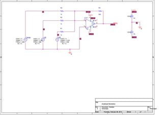
This document contains a circuit schematic for amplitude modulation. It shows a carrier signal generated by one voltage source being modulated by two lower frequency signals from other voltage sources. The output of the modulation circuit is measured over time, showing the amplitude of the output signal varying in accordance with the two modulating signals. Simulation data is included showing the output signal amplitude varying over time and with different input frequencies.

Recommandé
Contenu connexe
Tendances
Tendances (20)
En vedette
En vedette (20)
Similaire à Amplitude Modulation Circuit Simulation
Similaire à Amplitude Modulation Circuit Simulation (20)
Dernier
Dernier (20)
Amplitude Modulation Circuit Simulation
- 1. 5 5 4 4 3 3 2 2 1 1 D D C C B B A A 0V 0V 0V 0V +VCC12.00V -VCC 12.00V +VCC12.00V -VCC 4.800V AMout 12.00V 12.00V 0V 0 0 Title Size Document Number Rev Date: Sheet o f Schematic <RevCode> Amplitude Modulation A 1 1Thursday, February 06, 2014 Title Size Document Number Rev Date: Sheet o f Schematic <RevCode> Amplitude Modulation A 1 1Thursday, February 06, 2014 Title Size Document Number Rev Date: Sheet o f Schematic <RevCode> Amplitude Modulation A 1 1Thursday, February 06, 2014 USF FREQ = 102k VAMPL = 0.25 VOFF = 0 AC = 0 V5 12Vdc V4 12Vdc Carrier FREQ = 100k VAMPL = 1 VOFF = 0 AC = 0 R4 500 R3 1k U2 LF411 + 3 - 2 V+ 7 V- 4 OUT 6 B1 1 B2 5 R2 1k R1 1k LSF FREQ = 98k VAMPL = 0.25 VOFF = 0 AC = 0
- 2. Date/Time run: 02/06/14 23:49:50 ** Profile: "SCHEMATIC1-Sim_Profile" [ F:LABORATORY COURSESOrCADAmplitude_Modulation-PSpiceFilesSCHEMATIC1... Temperature: 27.0 Date: February 06, 2014 Page 1 Time: 23:51:07 (A) Sim_Profile.dat (active) Time 0s 1ms 2ms 3ms 4ms 5ms 6ms 7ms 8ms 9ms 10ms V(AMout) -800mV -400mV 0V 400mV 800mV
- 3. Date/Time run: 02/07/14 00:05:58 ** Profile: "SCHEMATIC1-Sim_Profile" [ F:Laboratory CoursesOrCADamplitude_modulation-pspicefilesschematic1... Temperature: 27.0 Date: February 07, 2014 Page 1 Time: 00:09:20 (A) Sim_Profile.dat (active) Frequency 40.0KHz 60.0KHz 80.0KHz 100.0KHz 120.0KHz 140.0KHz 160.0KHz 180.0KHz V(AMout) 0V 100mV 200mV 300mV 400mV 500mV