
Recommandé
Contenu connexe
Tendances
Tendances (20)
Similaire à Three phase balanced load circuits and synchronous generators
Similaire à Three phase balanced load circuits and synchronous generators (20)
Plus de Isham Rashik
Plus de Isham Rashik (20)
Dernier
Dernier (20)
Three phase balanced load circuits and synchronous generators
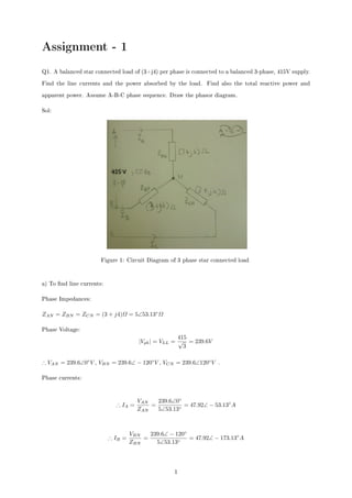
- 1. Assignment - 1 Q1. A balanced star connected load of (3+j4) per phase is connected to a balanced 3-phase, 415V supply. Find the line currents and the power absorbed by the load. Find also the total reactive power and apparent power. Assume A-B-C phase sequence. Draw the phasor diagram. Sol: Figure 1: Circuit Diagram of 3 phase star connected load a) To nd line currents: Phase Impedances: ZAN = ZBN = ZCN = (3 + j4)Ω = 5∠53.13◦ Ω Phase Voltage: |Vph| = VLL = 415 √ 3 = 239.6V ∴ VAN = 239.6∠0◦ V , VBN = 239.6∠ − 120◦ V , VCN = 239.6∠120◦ V . Phase currents: ∴ IA = VAN ZAN = 239.6∠0◦ 5∠53.13◦ = 47.92∠ − 53.13◦ A ∴ IB = VBN ZBN = 239.6∠ − 120◦ 5∠53.13◦ = 47.92∠ − 173.13◦ A 1
- 2. ∴ IC = VCN ZCN = 239.6∠120◦ 5∠53.13◦ = 47.92∠66.87◦ A Hence Line currents : |IA| = |IB| = |IC| = |IL| = |Iph| = 47.92A b)To nd power absorbed by the load, total reactive power and apparent power: Active Power(P), Reactive(Q) and Apparent Power(S): P = 3VphIph cos φ =? cos φ = Rph |Zph| = 3 5 = 0.6 Lagging as it is +ve jXL. ∴ P = 3 × 239.6 × 47.92 × 0.6 = 20, 667W = 20.67kW Hence absorbed power by the load = 20.67kW φ = cos−1 (0.6) = 53.13◦ ∴ sin φ = sin(53.13◦ ) = 0.8 ∴ Q = 3VphIph sin φ = 3 × 239.6 × 47.92 × 0.8 = 27, 544W = 27.54kW Hence total reactive power = 27.54kW To calculate Apparent Power (S): S2 = P2 + Q2 ∴ S = P2 + Q2 = ((20, 667)2 + (27, 544)2) = 34, 435W = 34.44kW Apparent Power = 34.44kW 2
- 3. c) Phasor Diagram: Figure 2: Phasor Diagram for phase voltages From phasor diagram: VAB = VAN + (−VBN ) ∴ VAB = VAN − VBN ∴ VAB = 239.6∠0◦ − 239.6∠ − 120◦ = 415∠ − 30◦ V Q2. A three-phase balanced delta connected coil having a resistance of4Ω per phase and inductance of 25.46mH per phase is connected across 415V, 50 Hz, three-phase supply. Determine the phase cur- rents and line currents. Also calculate total active, reactive and apparent power. Assume A-B-C phase sequence. Sol: For Delta : VL = Vph IL = √ 3Iph XL = ωL = 2πfL = 2π × 50 × 25.46 × 10−3 = 8Ω a)To compute phase currents: 3
- 4. Phase impedances: ZAB = ZBC = ZCA = Zph = 4 + j8Ω = 8.94∠63.43◦ Ω Figure 3: Circuit Diagram for 3 phase delta connected load Phase voltages: |VL| = |Vph| = 415V ∴ VAB = 415∠0◦ , VBC = 415∠ − 120◦ , VCB = 415∠120◦ Phase currents: ∴ IAB = VAB ZAB = 415∠0◦ 8.94∠63.43◦ = 46.42∠ − 63.43◦ A ∴ IBC = VBC ZBC = 415∠ − 120◦ 8.94∠63.43◦ = 46.42∠ − 183.43◦ A ∴ ICA = VCA ZCA = 415∠120◦ 8.94∠63.43◦ = 46.42∠56.57◦ A b)To compute line currents: ∴Line currents: |IL| = √ 3|Iph| = √ 3 × 46.42 = 80.4A Apply KCL at node A: IA + ICA = IAB 4
- 5. ∴ IA = IAB − ICA = 46.42∠ − 63.43◦ − 46.42∠56.57◦ IA = (20.76 − j41.52) − (25.57 + j38.74) = −4.81 − j80.26 IA = 80.4∠ − 93.4◦ A Similarly for IB and IC: IB = 80.4∠ − 213.4◦ A delayed by 120◦ IC = 80.4∠ − 333.4◦ A delayed by 120◦ c) To calculate total active, reactive and apparent power: Active Power (P) = 3VphIph cos φ cos φ = Rph Zph = 4 8.94 = 0.447 ∴ P = 3 × 415 × 46.32 × 0.447 = 25, 710W = 25.7kW φ = cos−1 (0.447) = 63.44◦ ∴ sin φ = sin(63.44◦ ) = 0.894 Reactive Power (Q) = 3VphIph sin φ ∴ Q = 3 × 415 × 46.32 × 0.894 = 51, 555W = 51.6kW Apparent Power (S): S2 = P2 + Q2 ∴ S = P2 + Q2 = ((25, 710)2 + (51, 555)2) = 57, 610W = 57.6kW Q3 A three-phase 415V, 50Hz supply is connected to a factory which has a star connected motor requiring 30 kVA at a power factor of 0.8 lagging and a heating load (balanced) star connected requiring 7kW per 5
- 6. phase. Calculate the power drawn from the supply and the capacitance per phase necessary to obtain unity power factor of the combined load. Sol: a) To nd power drawn from supply: Load 1 - Induction motor, 30kVA, cosφ = 0.8, Y - connected Load 2 - Heating load, 7kW/phase, Y - connected Table 1: Data to calculate required variables Load Active Power(P) Reactive Power(Q) Apparent Power (S) cosφ φ Induction motor Scosφ Ptanφ 30kVA 0.8 (lag) φ=cos−1 0.8 = 30 × 0.8 = 24 × tan(36.86◦ ) = 36.86◦ = 24kW = 18kVAr Heating load 7 × 3 = 21kW 0 1 0 45kW 18kVAr Hence, Power drawn from supply = 24+21= 45kW b) The capacitance per phase necessary to obtain unity power factor of the combined load: Power factor correction: Figure 4: Power factor triangle tanφ1 = 18 45 = 0.4 φ1 = tan−1 (0.4) = 21.8◦ cos φ1 = cos(21.8◦ ) = 0.928 6
- 7. (lag) In order to raise power factor to 1, cos φ2 = 1, φ2 = 0◦ ∴Leading kVAr supplied by the capacitor bank : Qc = P[tanφ1 − tanφ2] Qc = 45, 000[tan(21.8◦ ) − tan(0◦ )] = 18, 000V Ar Qc = 3V 2 ph Xc Rearranging Qcgives: Xc = 3V 2 ph Qc = (3 × 239.62 ) 18, 000 = 9.57Ω Hence capacitance per phase in order to obtain unity power factor of combined load: C = 1 ωXc = 1 2π50 × 9.57 = 3.32 × 10⁻⁴ F = 0.33mF Q4. The power input to a 2000 V, 50 Hz, three-phase motor running on a full-load at an eciency of 90% is measured by two wattmeters. If the readings on the wattmeters are 300 kW and 100 kW respectively, nd a) Input power b) Power factor c) Line current d) Output power e) Per-phase Impedance of the load. Sol: a) To nd input power: Pin = W1 + W2 = 300 + 100 = 400kW Hence input power = 400,000W b)To nd Power factor: tanφ = √ 3[ W1 − W2 W1 + W2 ] tanφ = √ 3[ 300 − 100 300 + 100 ] = √ 3[ 200 400 ] = √ 3 × 0.5 7
- 8. ∴ tanφ = 0.866 φ = tan−1 0.866 = 40.9◦ power factor = cos φ = cos(40.9◦ ) = 0.76 (lag) c)To calculate Line Current: P = √ 3|VL||IL| cos φ ∴ IL = P ( √ 3|VL| cos φ) = 400, 000 ( √ 3 × 2000 × 0.76) ∴ IL = 151.93A d)To nd the output power: Pout = η × Pin Pout = 0.9 × 400 = 360kW e)To calculate per phase impedance of the load: It is assumed the induction motor load to have arranged in Delta Connection. So, VL = Vph and IL = √ 3Iph. Iph = IL √ 3 = 151.93 √ 3 ∴ |Iph| = 87.71A Hence, per phase impedance of the load (Zph): Vph = |Iph||Zph| 8
- 9. ∴ |Zph| = 2000 87.71 = 22.8Ω ∴ Zph = 22.8∠40.9◦ Ω = (17.23 + j14.93)Ω Q5. Write a short note on a) constructional details and types of synchronous generator b) Excitation scheme Sol: a) Constructional details and types of synchronous generator: The function of the synchronous generator is to convert mechanical energy from the turbine into electrical energy. This type of generator requires a winding that will carry direct current (or in small sizes a series of permanent magnets) in order to generate the magnetic ux. In most of the machinery, this excitation winding (known as the eld winding) is carried on the rotor at frequency of 50-60Hz, in order to rotate at synchronous speed. The synchronous generator consists of 2 parts: 1. Stator: Stator carries 3-phase armature windings (it is where the main voltage is induced). It is connected to the AC power supply. The armature windings are physically displaced from each other by 120 degrees. At the terminals of the armature, 3 phase power is obtained. 2. Rotor: Rotor carries eld windings (responsible for generating main magnetic eld). It is connected to an external DC source via slip rings and brushes or from special DC source mounted directly on the shaft of the machine. Once the rotor or the eld poles are made to rotate in the presence of armature windings placed on the stator, an alternating 3 phase voltage induced in the armature conductors thus resulting in the generation of 3 phase electrical power. Figure 5: Types of Synchronous Generator There are mainly two types of synchronous generator based on the type of rotor used in construction: 9
- 10. 1. Hydro generators or salient pole type generators: These machines makes use of salient pole type rotor. They are driven by water turbines at a speed ranging from 50 to 1000 rev/min. The speed is dependent on the type of turbine, which in turn depends on the head and the ow rate of the availability of water. At low speeds, the permissible rotor diameter will be several times its active length. Generally, the largest allowable diameter of rotor is used to maximize the machine's inertia which is an important part of governing the water turbine. Outputs up to 800MW have been achieved. 2. Turbo generators or non-salient pole type generators: These machines use a cylindrical rotor in which the eld winding is placed in axial slots. They are invariably driven by a steam turbine or a gas turbine. At ratings below 60MW a gear box may be used to provide a rotational speed of 3600 (2 pole) or 1800 rev/min (4 pole) to provide power at 60 Hz, or 3000 rev/min (2 pole) or 1500 rev/min (4 pole) to provide power at 50 Hz. Smaller machines may use a laminated construction for the rotor while larger machines will use a forged rotor. A feature of these machines is that their length is several times their diameter. Power outputs range from a few megawatts up to about 1500MW. b) Excitation schemes: Any electric generators or motors consists of a rotor spinning in a magnetic eld. The magnetic eld can be generated by permanent magnets or by eld coils. In the case of a machine with eld coils, current must ow in the coils to generate the eld. This is to ensure power transfer to take place, in or out of the rotor. The process of generating a magnetic eld via means of an electric current is called excitation. Mainly two types of excitation schemes are used in the power stations: 1. Separate excitation: For large or older generators, it is usual for a separate exciter dynamo to be operated in conjunction with the main power generator. It is a small permanent-magnet or battery- excited dynamo that produces the eld current for the larger generator. 10
- 11. Figure 6: Circuit of separately excited generator 2. Self excitation: Modern generators with eld coils are self-excited. Some of the power output from the rotor is used to power the eld coils. The magnetism is retained by the rotor iron even after the generator is turned o. The generator is initially started with no load connected to it. The initial weak eld creates a weak voltage in the stator coils, which in turn increases the eld current, until the machine shoots to full voltage. Figure 7: Circuit of self excited generator 11