introduction to completions and workovers (2)
•Télécharger en tant que PPT, PDF•
3 j'aime•1,550 vues

this is brief introduction about well completions and workovers by request of students for education purposes

Recommandé
Contenu connexe
Tendances
Tendances (20)
Similaire à introduction to completions and workovers (2)
Similaire à introduction to completions and workovers (2) (20)
Plus de Dr. Arzu Javadova
Plus de Dr. Arzu Javadova (20)
Dernier
Dernier (20)
introduction to completions and workovers (2)
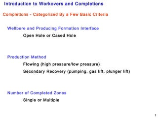
- 1. Introduction to Workovers and Completions 1 Completions - Categorized By a Few Basic Criteria Wellbore and Producing Formation Interface Open Hole or Cased Hole Production Method Flowing (high pressure/low pressure) Secondary Recovery (pumping, gas lift, plunger lift) Number of Completed Zones Single or Multiple
- 2. Introduction to Workovers and Completions 2 Open Hole Completion Advantages of an open hole completion: Simple, fast, and inexpensive Provides for more surface area of the pay to be exposed to the wellbore No perforating required Casing costs are drastically reduced The well design easily lends itself to deepening Disadvantages of an open hole completion: Well control can be complicated due to the massive fluid loss to the producing formation Not recommended for formations that are layered and have varying permeability Casing may need to be set before the pay is drilled or logged
- 3. Introduction to Workovers and Completions 3 Cased Hole Completion Flowing Well A flowing well is one which flows hydrocarbons to the surface using naturally-occurring formation pressure as the driving force. A formation pressure need not be very great to flow hydrocarbons to the surface. Gas, being a very light fluid does not require a great deal of pressure to overcome its hydrostatic pressure. Conversely, oil, being considerably denser than gas, requires more minimal formation pressure than gas to flow to the surface. A flowing well generally has the lowest lifting costs therefore making it more profitable than a well using a secondary recovery method.
- 4. Introduction to Workovers and Completions 4 Secondary Recovery Cased Hole Completion Injection Gas Produced Oil Pumping wells and wells using gas lift are usually in the category of secondary recovery. Secondary recovery methods are those employed after formation pressure has decreased to the point that produced fluid hydrostatic pressure equals formation pressure. When this occurs the well ceases to produce naturally. Produced Oil
- 5. Introduction to Workovers and Completions 5 Secondary Recovery Cased Hole CompletionAnother form of secondary recovery utilizes injected gas or liquids to maintain, enhance, or regain production from a depleting formation. Injection Well Producing Well Producing Well
- 6. Introduction to Workovers and Completions 6 Secondary Recovery Cased Hole Completion A third means of secondary recovery is in the form of an electrically-powered submursible pump. Submursible pumps are available in a range of sizes depending on whether the pump is to be run in the casing or tubing. They are also available in a range of pumping capacities based on the fluids to be produced and the potential productivity of the well into which they are to be used. To Electrical Supply
- 7. Introduction to Workovers and Completions 7 Cased Hole Completion Single and Multi-Zone Completions Depending on local subsurface geology, wells may be drilled and completed into either single or multiple pay zones. Multiple pay zones can be completed as dual completions as the well on the right, but can also be completed as single string completions.
- 8. Introduction to Workovers and Completions 8 Repair Mechanical Damage Mechanical damage comes in many forms: Failed or failing wellheads Failed safety valves Gas lift equipment Worn tubing Nipples Failed Sliding sleeves Leaking Packers Holes in the tubing Failed Casing In some instances the repair can be performed without killing the well and done with some form of well servicing unit. In other cases the well has to be killed and a rig put on the well to remove all tubulars and tools and then be reinstalled with refurbished or new equipment. Reasons For Workovers Failed Wellhead Failed Safety Valve Failed Gas Lift Equipment Worn Tubing Nipple Failed Sliding Sleeve Failed Packer Hole In Tubing
- 9. Introduction to Workovers and Completions 9 Reservoir stimulation is a process in which a mild acid is introduced through the perfs and into an existing producing reservoir. The purpose is to dissolve acid-soluble solids which usually “opens” clogged permeability and regains or restores production. Stimulation can be done by bullheading, using a coiled tubing unit, snubbing unit, or small tubing unit. Reservoir Stimulation Reasons For Workovers
- 10. Introduction to Workovers and Completions 10 Gravel Packing or Repairing A Gravel Pack A gravel pack completion is used where the producing formation lacks sufficient consolidation to withstand the friction caused by fluid flow from the formation to the wellbore. A slurry of “sand” and viscous liquid is pumped down the workstring and into the annular space between the casing and the screen until it is filled, or “sands out.” Excess sand slurry remaining in the workstring is reversed out. Another similar operation, known as a frac pack, involves pumping the sand slurry at high rates forcing the mixture far out into the producing formation. Reasons For Workovers Sump Packer Gravel Pack Packer
- 11. Introduction to Workovers and Completions 11 Here the lower depleted zone has been isolated with a plug conveyed by either coiled tubing or wireline. After the plug has been successfully set and tested the sliding sleeve is opened allowing production from the upper zone. Accessing A New Reservoir Plug set in tubing nipple Open sliding sleeve When a well is drilled through multiple producing zones and completed with a single production string it is common to produce the lower zone first. Upon depletion of the lower zone, the upper zone is then produced. This can be done in a variety of ways but usually entails abandoning the lower zone before production begins from the upper zone. Reasons For Workovers
- 12. Introduction to Workovers and Completions 12 Another means of completing a new reservoir: Cut the production tubing just above the packer with an electric line or coiled tubing conveyed tubing cutter Set and test a cement plug above the packer Perforate the new zone and begin production Reasons For Workovers Accessing A New Reservoir
- 13. Introduction to Workovers and Completions 13 Completing Multiple Reservoirs A dual completion, such as this one, allows for production from two zones simultaneously through two separate strings of tubing. The deeper string is commonly referred to as the long string while the shallower tubing string is known as the short string. Reasons For Workovers
- 14. Introduction to Workovers and Completions 14 Unwanted Water Production Water Oil Water, if present in a producing formation, is the lowermost fluid due to its density. And if the presence of water is known, a well will be completed above the oil- to-water contact. As the well is produced is conducted, the oil-to- water contact rises and eventually the water invades the lower perfs resulting in unwanted water production. Water Oil Reasons For Workovers
- 15. Introduction to Workovers and Completions 15 Unwanted Gas Production Additionally, the drive mechanism is being depleted which will shorten the duration of the flowing phase of the well. This can be temporarily remedied by squeezing cement into the perfs. But eventually mostly gas will be produced as the producible oil is depleted. In a gas cap driven reservoir, the gas cap expands as oil is produced. Eventually the expanding gas cap encroaches on the perforations and gas production will begins. The drawbacks are: the drive mechanism is being produced and the production train may not be able to handle the gas being produced. Reasons For Workovers Gas Oil Gas Oil
- 16. Introduction to Workovers and Completions 16 Water Oil Unwanted Water Production Squeezing The Perfs Reasons For Workovers The usual remedy for unwanted gas or water production is to squeeze the perfs with cement in hopes that the “watered- out” perfs will be plugged and the water production decreased. The process entails identifying the affected perfs then running an setting a squeeze packer just above the affected perfs. Cement is them pumped down the workstring and into the perfs.
- 17. Introduction to Workovers and Completions 17 Water Coning Excessive production rates in a water driven formation can create a condition known as water coning. Water coning results in water being pulled up into the perfs. Water production will usually continue so long as the well produces regardless of the production Decreasing the production rate, a commonly tried technique, rarely reduces the water production. The “quick fix” is to locate and block squeeze the affected perfs and decrease production rate. Reasons For Workovers GAS Water Oil Water Coning
- 18. Introduction to Workovers and Completions 18 Repair Failed Cement Jobs Evidence of a failing cement job usually manifests as pressure appearing on the intermediate casing string and the presence of chunks of cement in the choke body. This may also be accompanied by a decrease in daily production as surface lines can become clogged with cement. Repairing this usually entails killing the well, squeezing cement into the perforations, recompleting and reperforating the well. Reasons For Workovers
- 19. Introduction to Workovers and Completions 19 Pack-Off A Hole In The Tubing Or Casing Reasons For Workovers Upper Slip Stop Lower Slip Stop Upper Pack-Off Lower Pack-Off Spacer Pipe If a hole in wellbore tubulars develops, a workover can be temporarily postponed by running a tubing pack-off. This can be done on slickline, coiled tubing, or small jointed pipe, but is commonly conveyed in slickline.
- 20. Introduction to Workovers and Completions 20 Tubing String Replacement During the life of a well it may become necessary to replace the entire tubing string due to excessive wear. Wear can be in the form of erosional wear caused by sand production or pitting and corrosion caused by hydrogen sulfide or carbon dioxide. Premature failure can also occur due to excessive hole deviation. Reasons For Workovers
- 21. Introduction to Workovers and Completions 21 Artificial Lift Installation – Rod Pump Weatherford Downhole Rod Pump Walking Beam Horsehead Bridle Polished Rod Wellhead and Stuffing Box In pumping installations, points of wear include the rods, tubing string, and the downhole pump. Reasons For Workovers
- 22. Introduction to Workovers and Completions 22 The Plunger Lift System consist of a plunger, piston, two bumper springs, a lubricator to sense and stop the plunger as it arrives at the surface, and one of several different styles of controller. The plunger travels from the bottom of the well to the surface lubricator on the wellhead when the force of the lifting gas energy below the plunger is greater than the liquid load above the plunger. Any gas that bypasses the plunger during the lifting cycle flows up the production tubing and sweeps the area to minimize liquid fallback. The increments of the travel cycle are controlled by a surface controller and may be repeated as often as needed. The Plunger Lift has several points of wear: the plunger and associated seals, the downhole bumper, and the surface pressure control equipment including the wellhead and lubricator. Additionally, the well may have to be worked over due to tubing failure Weatherford Plunger Lift System Artificial Lift Installation – Plunger Lift Reasons For Workovers
- 23. Introduction to Workovers and Completions 23 Artificial Lift Installation – Gas Lift Gas Lift Installation This system can be installed during the initial completion or at a later time through a workover. Failures of the system can be surface control equipment and failed gas lift valves. Surface equipment cab be repaired without downhole intervention but repairing faulty gas lift valves requires intervention by slickline, coiled tubing or a workover rig. Halliburton Gas Lift Installation Reasons For Workovers
- 24. Introduction to Workovers and Completions 24 Producing Formation Basics Reasons For WorkoversFormation Damage In order for a formation to produce commercial quantities of hydrocarbons several things must be in place: Obviously hydrocarbons must be present; the by-products of complex chemical and physical changes. Organic debris accumulates in muds at the bottom of marine environments (fresh and salt water). Deposition buries the organic material and mud. In time and under the right conditions, hydrocarbons form and begin their slow migration to the surface since they are lighter in density than the surrounding formation waters. The muds further compress and form shales. Hydrocarbons collect in porous rock formations that are overlain by non-porous rock layers. Sandstones and carbonates (limestones) make up the bulk of reservoir rocks. Structural traps must be present – rock layers that allow hydrocarbons to accumulate without escaping. Rock characteristics: adequate porosity and permeability.
- 25. Introduction to Workovers and Completions 25 Pore Spaces Porosity – Simply defined porosity is the spaces between the sand grains. Typically porosity averages between 25% - 35%. That is to say that roughly 25% to 35% of a given volume of rock is not rock but pore spaces. It is in these spaces that hydrocarbons accumulate. Porosity
- 26. Introduction to Workovers and Completions 26 Flow Permeability Permeability can be defined as the ability of a formation to allow fluid flow, or how well the pores of the formation are connected. Permeability is measured in units known as Darcies. Apparent, or relative permeability has to do with the ability of a formation to allow various types of fluids to flow through it. This is affected by the nature of the fluid that “wets” the sand grains. A “water-wet” sand allows both oil and gas to flow through it compared to an “oil wet” sand.
- 27. Introduction to Workovers and Completions 27 Anticline Trap Oil and/or Gas Traps
- 28. Introduction to Workovers and Completions 28 Traps Intrusive Tectonic Activity Salt Dome Oil Oil Salt Dome
- 29. Introduction to Workovers and Completions 29 Fault Oil and/or Gas Fault TrapTraps
- 30. Introduction to Workovers and Completions 30 Unconformity Trap Traps Oil & Gas
- 31. Introduction to Workovers and Completions 31 Folded and Faulted Trap Traps
- 32. Introduction to Workovers and Completions 32 Cement Filtrate Invasion – solids invasion while drilling PIPE DOPE Perforator Debris Iron Sulfide Scale Dirty Completion Fluid Causes of Formation Damage
- 33. Introduction to Workovers and Completions 33 Causes of Formation Damage – While Drilling FILTRATE INVASION Filtrate invasion usually occurs while the well is drilled. Drilling mud use to drill wells contains solids, drilled up solids and commercially added solids. These solids are suspended in the fluid while it is circulated. Formation invasion takes place when the mud comes into contact with a porous and permeable formation and the pressure in the hole at the depth of the formation is greater than the naturally occurring formation pressure. Excessive filtration invasion can reduce the permeability of a formation and inhibit production.
- 34. Introduction to Workovers and Completions 34 CEMENT INVASION In a similar fashion to drilling solids, cement can invade a formation when casing is cemented into place. And like drilling solids, cement invasion can reduce formation permeability and productivity potential. Causes of Formation Damage – While Drilling
- 35. Introduction to Workovers and Completions 35 Causes of Formation Damage – While Completing or Working Over PIPE DOPE Other sources of formation damage occur during production, completions and workovers. The worst damage is caused by pipe dope. Pipe dope, while necessary, is commonly used to excess. This excess finds its way out of the workstring through fluid circulation and into producing formations where it decreases permeability. Pipe dope, once deposited, is virtually impossible to remove, so the damage is permanent. PERFORATOR DEBRIS When a perforator goes off it pushes various types of chemical and metallic debris into the producing formation. This debris, if not flowed out of the formation, can remain and decrease near-wellbore permeability. Because of this, some wells are perforated underbalanced to initiate an immediate flow into the well following perforation. DIRTY COMPLETION FLUID The fluid of choice in most completions and workovers is a solids-free brine. Brines can be mixed to supply sufficient density to control even the most extreme formation pressure – Calcium Bromide/Zinc Bromide can be mixed to a stable density of 20.2 ppg. And this is accomplished without solids, which can cause formation damage. It defies logic to use a solids free fluid and then mix and store it in dirty pits and fail to filter it when it is circulated through the well. IRON SULFIDE SCALE Iron sulfide, a compound created from the chemical combination of iron and sulfur, collects on the inside of the tubing string and can be dislodged during trips into and out of the hole. Naturally, this bulk of this debris remains in the well and is circulated around by the workover fluid, but some does find its way into the producing formation and can reduce permeability.