Duro-Sense Sheath-Pak Mineral Insulated Thermocouples
•
0 j'aime•192 vues

Mineral insulated thermocouples are rugged, high temperature sensors made from a drawn tube filled with magnesium oxide and the thermocouple conductor wire.

Recommandé
Recommandé
Contenu connexe
Dernier
Dernier (20)
En vedette
En vedette (20)
Duro-Sense Sheath-Pak Mineral Insulated Thermocouples
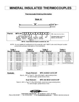
- 1. MINERAL INSULATED THERMOCOUPLES Thermocouple Ordering Information Style ‘A’ Part #: MTC-A- - - - Sheath Calibration Sheath Junction Length SP* Diameter (Table 2) Material able 4) (inches)(T (Table 1) (Table 3) *SP = Special Limits of Error If standard limits of error is desired, omit this field. NOTE: Dual Element Style is notated as ‘AA’ NOTE: For any additional modifications to this assembly, add “-MOD” to the end of the part number and provide a physical description of the modification. Table 1 Table 2 Table 3 Table 4 Sheath Diameter Calibration Sheath Material Junction P/N Description P/N Description P/N Description P/N Description 010 .010 inches 1 Type ‘J’ 1 Alloy 600 E Exposed 020 .020 inches 2 Type ‘K’ 2 304 S.S. G Grounded 032 .032 inches 3 Type ‘T’ 3 316 S.S. U Ungrounded 040 .040 inches 4 Type ‘E’ 4 310 S.S. EE Dual Exposed 063 .063 inches 5 Type ‘R’ 5 321 S.S. GG Dual Grounded 090 .090 inches 6 Type ‘S’ 6 446 S.S. UU Uncommon- Ungrounded 125 .125 inches 7 Type ‘B’ 7 MI2300 CU Common-Ungrounded 188 .188 inches 8 Type ‘N’ X Special 250 .250 inches X Special 313 .313 inches 375 .375 inches XXX Special Example: Single Element MTC-A-06321-U-012-SP Style A, .063” φ, Type ‘K’, Alloy 600 sheath, ungrounded junction, 12” active length, special limits of error. Dual Element: MTC-AA-06321-UU-012-SP Style A, .063” φ, Type ‘K’, Alloy 600 sheath, uncommon-ungrounded junction, 12” active length, special limits of error. DURO-SENSE CORPORATION 869 Sandhill Ave., Carson, CA 90746 Phone: (310) 533-6877 -- Fax: (310) 533-0330 – E-mail: dscsales@duro-sense.com -- Website: www.duro-sense.com
- 2. MINERAL INSULATED THERMOCOUPLES Thermocouple Ordering Information Style ‘B’ Part #:MTC-B- - - - - - Sheath Calibration Sheath Junction Sheath Lead SP* Cold End Diameter (Table 2) Material (Table 4) Length Length Termination (Table 1) (Table 3) (inches) (inches) *SP = Special Limits of Error If standard limits of error is desired, omit this field. NOTE: Dual Element Style is notated as ‘BB’ NOTE: For any additional modifications to this assembly, add “-MOD” to the end of the part number and provide a physical description of the modification. Table 1 Table 2 Table 3 Table 4 Table 5 Sheath Diameter Calibration Sheath Material Junction Cold End Termination P/N Description P/N Description P/N Description P/N Description P/N Description 010 .010 inches 1 Type ‘J’ 1 Alloy 600 E Exposed P Standard Plug 020 .020 inches 2 Type ‘K’ 2 304 S.S. G Grounded A Standard Plug 032 .032 inches 3 Type ‘T’ 3 316 S.S. U Ungrounded B Hi-Temp Plug 040 .040 inches 4 Type ‘E’ 4 310 S.S. EE Dual Exposed C Ceramic Plug 063 .063 inches 5 Type ‘R’ 5 321 S.S. GG Dual Grounded D Miniature Plug 090 .090 inches 6 Type ‘S’ 6 446 S.S. UU Uncommon- Ungrounded E Miniature Hi-Temp Plug 125 .125 inches 7 Type ‘B’ 7 MI2300 CU Common-Ungrounded F Miniature Ceramic Plug 188 .188 inches 8 Type ‘N’ X Special G Standard Jack 250 .250 inches X Special H Hi-Temp Jack 313 .313 inches J Ceramic Jack 375 .375 inches K Miniature Jack XXX Special L Miniature Hi-Temp Jack M Miniature Ceramic Jack N Spade Lug P Ring Lug R Stripped Leads Only X Special Example: Single Element MTC-B-06321-U-012-048-SP-A Style B, .063” φ, Type ‘K’, Alloy 600 sheath, ungrounded junction, 12” active length, 48” lead length, special limits of error, standard male connector. Dual Element: MTC-BB-06321-UU-012-048-SP-AA Style B, .063” φ, Type ‘K’, Alloy 600 sheath, uncommon-ungrounded junction, 12” active length, 48” lead length, special limits of error, dual standard male connectors. DURO-SENSE CORPORATION 869 Sandhill Ave., Carson, CA 90746 Phone: (310) 533-6877 -- Fax: (310) 533-0330 – E-mail: dscsales@duro-sense.com -- Website: www.duro-sense.com
- 3. MINERAL INSULATED THERMOCOUPLES Thermocouple Ordering Information Style ‘C’ Part #: MTC-C- - - - Sheath Calibration Sheath Junction Length SP* Diameter (Table 2) Material able 4) (inches)(T (Table 1) (Table 3) *SP = Special Limits of Error If standard limits of error is desired, omit this field. NOTE: Dual Element Style is notated as ‘CC’ NOTE: For any additional modifications to this assembly, add “-MOD” to the end of the part number and provide a physical description of the modification. Table 1 Table 2 Table 3 Table 4 Sheath Diameter Calibration Sheath Material Junction P/N Description P/N Description P/N Description P/N Description 010 .010 inches 1 Type ‘J’ 1 Alloy 600 E Exposed 020 .020 inches 2 Type ‘K’ 2 304 S.S. G Grounded 032 .032 inches 3 Type ‘T’ 3 316 S.S. U Ungrounded 040 .040 inches 4 Type ‘E’ 4 310 S.S. EE Dual Exposed 063 .063 inches 5 Type ‘R’ 5 321 S.S. GG Dual Grounded 090 .090 inches 6 Type ‘S’ 6 446 S.S. UU Uncommon- Ungrounded 125 .125 inches 7 Type ‘B’ 7 MI2300 CU Common-Ungrounded 188 .188 inches 8 Type ‘N’ X Special 250 .250 inches X Special 313 .313 inches 375 .375 inches Example: Single Element MTC-C-06321-U-012-SP Style C, .063” φ, Type ‘K’, Alloy 600 sheath, ungrounded junction, 12” active length, special limits of error. Dual Element: MTC-CC-06321-UU-012-SP Style C, .063” φ, Type ‘K’, Alloy 600 sheath, uncommon-ungrounded junction, 12” active length, special limits of error. DURO-SENSE CORPORATION 869 Sandhill Ave., Carson, CA 90746 Phone: (310) 533-6877 -- Fax: (310) 533-0330 – E-mail: dscsales@duro-sense.com -- Website: www.duro- sense.com
- 4. MINERAL INSULATED THERMOCOUPLES Thermocouple Ordering Information Style ‘D’ *SP = Special Limits of Error If standard limits of error is desired, omit this field. Part #: MTC-D- - - - - Sheath Calibration Sheath Junction Length SP* HT* Diameter (Table 2) Material (Table 4) (inches) (Table 1) (Table 3) *HT = Hi-Temp Connector If standard connector is desired, omit this field. NOTE: Dual Element Style is notated as ‘DD’ NOTE: For any additional modifications to this assembly, add “-MOD” to the end of the part number and provide a physical description of the modification. Table 1 Table 2 Table 3 Table 4 Sheath Diameter Calibration Sheath Material Junction P/N Description P/N Description P/N Description P/N Description 010 .010 inches 1 Type ‘J’ 1 Alloy 600 E Exposed 020 .020 inches 2 Type ‘K’ 2 304 S.S. G Grounded 032 .032 inches 3 Type ‘T’ 3 316 S.S. U Ungrounded 040 .040 inches 4 Type ‘E’ 4 310 S.S. EE Dual Exposed 063 .063 inches 5 Type ‘R’ 5 321 S.S. GG Dual Grounded 090 .090 inches 6 Type ‘S’ 6 446 S.S. UU Uncommon- Ungrounded 125 .125 inches 7 Type ‘B’ 7 MI2300 CU Common-Ungrounded 188 .188 inches 8 Type ‘N’ X Special 250 .250 inches X Special 313 .313 inches 375 .375 inches Example: Single Element MTC-D-06321-U-012-SP-HT Style D, .063” φ, Type ‘K’, Alloy 600 sheath, ungrounded junction, 12” active length, special limits of error, hi-temp male connector. Dual Element: MTC-DD-06321-UU-012-SP-HT Style D, .063” φ, Type ‘K’, Alloy 600 sheath, uncommon-ungrounded junction, 12” active length, special limits of error, hi-temp male connectors. DURO-SENSE CORPORATION 869 Sandhill Ave., Carson, CA 90746 Phone: (310) 533-6877 -- Fax: (310) 533-0330 – E-mail: dscsales@duro-sense.com -- Website: www.duro-sense.com
- 5. MINERAL INSULATED THERMOCOUPLES Thermocouple Ordering Information Style ‘G’ *SP = Special Limits of Error If standard limits of error is desired, omit this field. Part #: MTC-G- - - - - Sheath Calibration Sheath Junction Length SP* HT* Diameter (Table 2) Material (Table 4) (inches) (Table 1) (Table 3) *HT = Hi-Temp Connector If standard connector is desired, omit this field. NOTE: Dual Element Style is notated as ‘GG’ NOTE: For any additional modifications to this assembly, add “-MOD” to the end of the part number and provide a physical description of the modification. Table 1 Table 2 Table 3 Table 4 Sheath Diameter Calibration Sheath Material Junction P/N Description P/N Description P/N Description P/N Description 010 .010 inches 1 Type ‘J’ 1 Alloy 600 E Exposed 020 .020 inches 2 Type ‘K’ 2 304 S.S. G Grounded 032 .032 inches 3 Type ‘T’ 3 316 S.S. U Ungrounded 040 .040 inches 4 Type ‘E’ 4 310 S.S. EE Dual Exposed 063 .063 inches 5 Type ‘R’ 5 321 S.S. GG Dual Grounded 090 .090 inches 6 Type ‘S’ 6 446 S.S. UU Uncommon- Ungrounded 125 .125 inches 7 Type ‘B’ 7 MI2300 CU Common-Ungrounded 188 .188 inches 8 Type ‘N’ X Special 250 .250 inches X Special 313 .313 inches 375 .375 inches Example: Single Element MTC-G-06321-U-012-SP-HT Style G, .063” φ, Type ‘K’, Alloy 600 sheath, ungrounded junction, 12” active length, special limits of error, hi-temp female connector. Dual Element: MTC-GG-06321-UU-012-SP-HT Style G, .063” φ, Type ‘K’, Alloy 600 sheath, uncommon-ungrounded junction, 12” active length, special limits of error, hi-temp female connectors. DURO-SENSE CORPORATION 869 Sandhill Ave., Carson, CA 90746 Phone: (310) 533-6877 -- Fax: (310) 533-0330 – E-mail: dscsales@duro-sense.com -- Website: www.duro-sense.com
- 6. MINERAL INSULATED THERMOCOUPLES Thermocouple Ordering Information Style ‘H’ Part #: MTC-H- - - - - - Sheath Calibration Sheath Junction Length SP* Process Head Diameter (Table 2) Material (Table 4) (inches) Fitting Style (Table 1) (Table 3) *SP = Special Limits of Error If standard limits of error is desired, omit this field. NOTE: Dual Element Style is notated as ‘HH’ NOTE: For any additional modifications to this assembly, add “-MOD” to the end of the part number and provide a physical description of the modification. Table 1 Table 2 Table 3 Table 4 Table 5 Table 6 Sheath Diameter Calibration Sheath Material Junction Process Fitting Connection Head P/N Description P/N Description P/N Description P/N Description P/N Description P/N Description 010 .010 inches 1 Type ‘J’ 1 Alloy 600 E Exposed A 1/4” NPT A Cast Aluminum 020 .020 inches 2 Type ‘K’ 2 304 S.S. G Grounded B 3/8” NPT B Miniature Aluminum 032 .032 inches 3 Type ‘T’ 3 316 S.S. U Ungrounded C 1/2” NPT C Cast Iron 040 .040 inches 4 Type ‘E’ 4 310 S.S. EE Dual Exposed D 3/4” NPT D Polypropylene 063 .063 inches 5 Type ‘R’ 5 321 S.S. GG Dual Grounded E 1” NPT E Miniature Plastic 090 .090 inches 6 Type ‘S’ 6 446 S.S. UU Uncommon- Ungrounded F 1 ¼” NPT F Explosion Proof 125 .125 inches 7 Type ‘B’ 7 MI2300 CU Common-Ungrounded G 1 ½” NPT G Canister Style 188 .188 inches 8 Type ‘N’ X Special X Special H None X Special 250 .250 inches X Special X Special 313 .313 inches 375 .375 inches Example: Single Element MTC-H-06321-U-012-SP-C-A Style H, .063” φ, Type ‘K’, Alloy 600 sheath, ungrounded junction, 12” active length, special limits of error, ½” NPT process threads, cast aluminum head. Dual Element: MTC-HH-06321-UU-012-SP-C-A Style H, .063” φ, Type ‘K’, Alloy 600 sheath, uncommon-ungrounded junction, 12” active length, special limits of error, ½” NPT process threads, cast aluminum head. DURO-SENSE CORPORATION 869 Sandhill Ave., Carson, CA 90746 Phone: (310) 533-6877 -- Fax: (310) 533-0330 – E-mail: dscsales@duro-sense.com -- Website: www.duro-sense.com