
Recommandé
Contenu connexe
Tendances
Tendances (20)
En vedette
Similaire à BS 2 Escalators 1of 2
Similaire à BS 2 Escalators 1of 2 (20)
Plus de Est
Plus de Est (20)
Dernier
Dernier (20)
BS 2 Escalators 1of 2
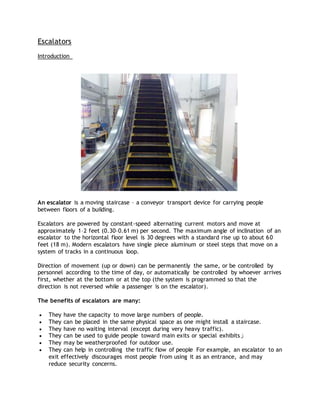
- 1. Escalators Introduction An escalator is a moving staircase – a conveyor transport device for carrying people between floors of a building. Escalators are powered by constant-speed alternating current motors and move at approximately 1–2 feet (0.30–0.61 m) per second. The maximum angle of inclination of an escalator to the horizontal floor level is 30 degrees with a standard rise up to about 60 feet (18 m). Modern escalators have single piece aluminum or steel steps that move on a system of tracks in a continuous loop. Direction of movement (up or down) can be permanently the same, or be controlled by personnel according to the time of day, or automatically be controlled by whoever arrives first, whether at the bottom or at the top (the system is programmed so that the direction is not reversed while a passenger is on the escalator). The benefits of escalators are many: They have the capacity to move large numbers of people. They can be placed in the same physical space as one might install a staircase. They have no waiting interval (except during very heavy traffic). They can be used to guide people toward main exits or special exhibitsز They may be weatherproofed for outdoor use. They can help in controlling the traffic flow of people For example, an escalator to an exit effectively discourages most people from using it as an entrance, and may reduce security concerns.
- 2. Escalators Basic Components Escalators Basic Components The Escalator consists of the following components: 1. Landing Platforms. 2. Truss. 3. Tracks. 4. Steps. 5. Handrail. 6. Escalator Exterior (Balustrade). 7. Drive system. 8. Auto-Lubrication System. 9. Braking system. 10.Safety devices. 11.Electrical & Control Systems.
- 3. First: Landing Platforms Landing Platforms
- 4. These two platforms house the curved sections of the tracks, as well as the gears and motors that drive the stairs. The top platform contains the motor assembly and the main drive gear, while the bottom holds the step return idler sprockets. These sections also anchor the ends of the escalator truss. In addition, the platforms contain a floor plate and a combplate. The floor plate provides a place for the passengers to stand before they step onto the moving stairs. This plate is flush with the finished floor and is either hinged or removable to allow easy access to the machinery below. The combplate is the piece between the stationary floor plate and the moving step. It is so named because its edge has a series of cleats that resemble the teeth of a comb. These teeth mesh with matching cleats on the edges of the steps. This design is necessary to minimize the gap between the stair and the landing, which helps prevent objects from getting caught in the gap. Major components of Landing Platforms are: Combplates also known as walk-on plates are an entrance and exit for the passengers to the steps. It provides mounting for the comb segments and combplate (comb impact) switch actuator. Comb Segments are replaceable sections, usually between 6” to 8” in width or maybe narrower, with teeth that mesh (comb) into the step treads. Comb segment may also be called a combplate by non-standard noun name. A left hand, a right hand, or a middle section comb segment can be identified by the pattern of the combs on their sides and by the width or number of combs. Access Covers used as an access to the pit area for inspection, maintenance, and repairs. The lower landing access cover plates provide access to the reversing station and step removal. The upper access cover plates may provide an access to the driving machine, bull gear, and sometimes the controller. Comb Lights are an optional safety device used to illuminate the area where steps and comb segments meet, mounted at the upper and lower landing above the comb segments. They are from a different power source that stays on always even if the unit is not running.
- 5. Second: Truss The escalator truss The escalator truss is the structural frame of the escalator and consists of three major areas: The lower section, Incline section, Upper section. It is a hollow metal structure that bridges the lower and upper landings. It is composed of two side sections joined together with cross braces across the bottom and just below the top. The ends of the truss are attached to the top and bottom landing platforms via steel or concrete supports. The truss carries all the straight track sections connecting the upper and lower sections. The structural steel truss members are designed to carry
- 6. the entire load of the escalator equipment and the steel covering without shifting more than specified by the contract requirements. The entire structure is rigid enough to maintain close operating tolerances but will allow for building shift and vibration because of a built-in system of shift- plates and Teflon pads. Third: Tracks Tracks system The track system is built into the truss to guide the step chain, which continuously pulls the steps from the bottom platform and back to the top in an endless loop. There are actually two tracks: One for the front wheels of the steps (called the step wheel track). One for the back wheels of the steps (called the trailer-wheel track). The relative positions of these tracks cause the steps to form a staircase as they move out from under the combplate. Along the straight section of the truss, the tracks are at their maximum distance apart. This configuration forces the back of one step to be at a 90- degree angle relative to the step behind it. This right angle bends the steps into a shape resembling a staircase. At the top and bottom of the escalator, the two tracks converge so that the front and back wheels of the steps are almost in a straight line. This causes the stairs to lay in a flat sheet-like arrangement, one after another, so they can easily travel around the bend in the curved section of track.
- 7. The tracks carry the steps down along the underside of the truss until they reach the bottom landing, where they pass through another curved section of track before exiting the bottom landing. At this point, the tracks separate and the steps once again assume a staircase configuration. This cycle is repeated continually as the steps are pulled from bottom to top and back to the bottom again. Three major assemblies of the tracks are: Upper. Incline. Lower. The track assembly is bolted but not welded on the truss for easy removal. Sometimes they are mounted on boilerplate (support plate mounted against the truss) or curve plates at the upper and lower landing sections. The tracks are used to guide steps wheels and step chains in their travel around the escalator truss. They are curved at the upper and the lower end of the incline to allow smooth transition of steps from the form of stairs to a horizontal movement, or vice versa. The lower and top end tracks are formed semi- circles to contain the chains and the step rollers going around them. Track assembly major components are: Track assembly major components
- 8. a. Circle Tracks or Crab tracks (A) are located at the top and bottom pits. Most of the outer circle tracks have access windows for easy step removal. Some are mounted on a removable or replaceable curve plate. The Montgomery & Montgomery KONE escalators circle tracks at the lower reversing station are part of the “make-up track” that travels with the carriage. Circle tracks provide smooth step travel at the end of the tracks. The distance of the inside circle track from the carriage shaft of Westinghouse escalator is used to measure the wear of the step chain. b. Beveled Track (B) provides smooth transition of chain wheels to and from the carriage sprockets. Beveled track eliminates the bumping effect of the chain wheels to the tracks, thus minimizing premature wear and damage to the wheels. c. Chain Wheel, Upper Upthrust (hold down) Track (C) is used to hold down and guide chain wheels to and from the transition. d. Chain Wheel, Upper Line Track (D). Used to support the chain wheels to/from the bull gear sprockets' top end through the incline area down to the carriage sprockets' top, or vice versa. e. Step Wheel, Lower Upthrust Track (E). A few feet of track used to hold down and guide step wheels to and from the transition area. f. Step Wheel, Lower Line Track or Flat Track (F) works in conjunction with the lower upthrust step wheel track. Flat track supports the step wheels in either ascending or descending through the incline. g. Chain Wheel, Return Track (G) is used to support the chain wheels from the bull gear lower end to the carriage lower end, or vice versa. h. Step Wheel, Return Track (H). Slightly above the chain wheel return track at the incline section of the non-passenger side. Step wheel return track is used to position the step treads to run in parallel with the chain wheel return track. Forth: Steps The steps are solid, one piece, die-cast aluminum or steel. Yellow demarcation lines may be added to clearly indicate their edges. The steps are linked by a continuous metal chain that forms a closed loop. The front and back edges of the steps are each connected to two wheels. The rear wheels are set further apart to fit into the back track and the front wheels have shorter axles to fit into the narrower front track. As described above, the position of the tracks controls the orientation of the steps.
- 9. Steps Major Components Steps Major Components The Step Plate (Tread) is the surface area of the step people step on. The step plate is usually made of an aluminum plate with longitudinal cleats or grooves that run through the combs and provide secure footing. The Step Riser is the vertical cleat cast into the front of a step, designed to pass between the cleats of adjacent step, thus creating a combing action with minimum clearance for safety. The Demarcations are yellow strips or may be in bold color around the step tread but mostly located at the front and at the rear ends of the tread. They are used to visually locate the step separation and visual contrast between the steps and the combs. Frame/Yoke - main support for riser, step tread, and step wheels Trail Wheels are used to guide the step and support its load on the track and prevent it from being out of plane. Step Hook normally attached to the end of the yoke by the step wheel used to activate the step up thrust safety device when the steps are not on their plane of travel at the top and bottom inclines. Note: The length of the step is measured from both ends of the step tread (front and rear) and the width is from both sides of the step.
- 10. Sixth: Handrail Handrail Assembly The Handrail provides a convenient handhold for passengers while they are riding the escalator. In an escalator, the handrail is pulled along its track by a chain that is connected to the main drive gear by a series of pulleys. The Handrail is constructed of four distinct sections:
- 11. Handrail Components At the center of the handrail is a "slider “also known as a "glider ply," which is a layer of a cotton or synthetic textile. The purpose of the slider layer is to allow the handrail to move smoothly along its track. The next layer, known as the “tension member” consists of either steel cable or flat steel tape and provides the handrail with tensile strength and flexibility. On top of the tension member are the inner construction components which are made of chemically treated rubber designed to prevent the layers from separating. Finally, the outer layer, the only part that passengers actually see is the cover which is a blend of synthetic polymers and rubber, this cover is designed to resist degradation from environmental conditions, mechanical wear and tear, and human vandalism. Seventh: Escalator Exterior (Balustrade) Escalator Exterior (Balustrade) The Balustrade consists of the handrail and the exterior supporting structure of the escalator. It is the escalator exterior components extending above the steps and it supports the handrail. It is either designed as Interior Low-deck or Interior High-deck. The balustrade may also refer to the individual interior panels, skirt panels, and deck covers of the escalator. Each interior balustrade panel section is individually removable to allow easy access to the escalator interior for cleaning, maintenance, and component replacement.
- 12. Escalator Exterior (Balustrade) Components: 1. Interior Low-deck has interior or side panels that are usually glass panels that support the handrail base. 2. Interior High-deck is the side panel and is usually aluminum or steel alloy sheets, sometimes called solid panels. The major components of interior high-deck are: a. Skirt Panel - commonly called a “Skirt." It is the interior covering of the balustrade located alongside the steps. It houses the actuator for the skirt safety switch. Side Safety Brushes are installed slightly above the step level on the skirt panel to provide passenger safety between the side of the steps and the skirt. b. Interior Panel - commonly called “side panel" by mechanics. The central point of the balustrade that supports the handrail base and sets the proper elevation for handrails on a glass balustrade. It provides access to the handrail; driver, idlers, sheaves, skirt switches in interior high-deck balustrades, and various components. c. Handrail Stand - the handrail tracks or guides located above the side panels or maybe the upper deck. d. High-deck Interior - the top most, inner part of the balustrade that supports the handrail track or guide. e. High-deck Exterior - top most outer covering of the balustrade outside and above the side panels. Supports the outer side of the handrail guide. If the outer edge of the deck is greater than 12 inches from centerline of the handrail, an anti-slide device or sometimes called baggage stops (like a hockey puck) must be installed. f. Low-deck Interior or Inner Decks - the inner covering of the balustrade located between the glass panels and the skirts. Provide access to the handrail drivers and skirt switches in interior low-deck balustrades. g. Low-deck Exterior or Outer Decks - the outer covering of the balustrade located outside the glass panels. h. Exterior Panel is an outer covering below the high-deck exterior. i. Newel - is the balustrade termination at the upper and the lower landing of the escalator in a semi-circle shape. It normally houses the following switches; emergency stop, on/off, up/down or directional indicator lighting, Entry to and exit from the escalator normally occurs at one of the newels and several important features are conveniently located at each. j. Newel Base or Front Plates - supports the newel stand and it may house the Handrail Inlet (Guard) Safety Device.
- 13. k. Emergency Stop Button is the most important feature at each Newel. The Emergency Buttons are located so that anyone can stop the escalator if there is a need. These switches have a lift cover that will sound an audible alarm when lifted. When either button is pushed, power to the electrical drive motor is shut off and the escalator brake is applied. l. Key Operated Switches are located on each Newel and they are used to control the “ON” and “OFF” operation and the direction of escalator travel. These switches are intended for the use of authorized personnel only.