EVANNEX EcoHitch for Tesla Model S Install Guide
•
1 j'aime•427 vues

EVANNEX EcoHitch for Tesla Model S Install Guide

Recommandé
Contenu connexe
Tendances
Tendances (18)
En vedette
En vedette (16)
Similaire à EVANNEX EcoHitch for Tesla Model S Install Guide
Similaire à EVANNEX EcoHitch for Tesla Model S Install Guide (20)
Plus de EVANNEX Aftermarket Tesla Accessories
Plus de EVANNEX Aftermarket Tesla Accessories (20)
Dernier
Dernier (20)
EVANNEX EcoHitch for Tesla Model S Install Guide
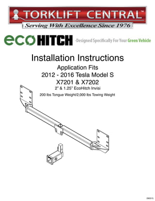
- 1. SAFETY FIRST! L) L) 2013-2015 TESLA MODEL S Installation Instructions Application Fits 2012 - 2016 Tesla Model S X7201 & X7202 2” & 1.25” EcoHitch Invisi 200 lbs Tongue Weight/2,000 lbs Towing Weight 090315
- 2. Bolt Kit Weight-539g +/- Hardware Included QTY Fastener 2 3/8” Flat Washers 2 3/8” Lock Washers 2 3/8” - 16 Nuts 2 3/8” - 16 x 1” Bolt 1 1/2” Flat Washer 1 1/2” Lock Washer 1 1/2”-13 x 2-1/2” Bolt 2 10mm Lock Washer 2 M10 - 1.5 x 20mm Stud Extender 14 M10 - 1.5 Serrated Flange Nuts 2 M10 - 1.5 x 20mm Bolt 2 Frame Plate Strap 2 Velcro Square 1 11” Zip-tie Step 1. Raise rear of vehicle off of ground and place on ramps or suitable jack stands. Note: It is recommended to place the vehicle in “Very High” suspension mode to ease in installation if performing on ramps. If using a hoist/lift ensure that you are utilizing the Tesla approved lifting points/hoist adapters. IT IS HIGHLY RECOMMENDED THAT YOU HAVE A PROFESSIONAL BODY SHOP/INSTALLATION FACILITY PERFORM THE INSTALLATION. DUE TO THE NUMBER OF BOLTS AND FASTENERS BEING REMOVED IT IS HIGHLY RECOMMENDED THAT YOU LABEL EVERY PIECE OF HARDWARE REMOVED AND WHICH PANEL IT WAS REMOVED FROM FOR EASE OF RE- ASSEMBLY READ THESE INSTRUCTIONS THOROUGHLY AND ACCOUNT FOR ALL HARDWARE LISTED BEFORE BEGINNING INSTALLATION! Pg. 2
- 3. Step 2. Locate the underbelly panels. Start by removing the innermost fins that are connected to the chrome trim. Once the bolts/clips are removed, the fins unsnap from the panel. Gently pull in a downward motion. Repeat on opposite side as well as outermost fins. See Figures [1] & [2]. Step 3. Disconnect lower underbelly panel closest to the rear. There are many fasteners in this step and it is recommended to label the locations of these fasteners. There are specific machine screws and lag style screws, incorrect re-installation could lead to the “cross-threading” of threads. Fig [1] Fig [2] Fig [3] Pg. 3
- 4. Step 4. Remove the next underbelly panel towards the front of the car from the panel just removed. Step 5. Locate the lower rear inner fender well. Picture shown is of the passenger side. Remove the two lower two piece clips where attached to the bumper. Then remove the three rear most visible clips (This allows access to a hidden bolt in a another step). Repeat on opposite side. Fig [4] Fig [5] Fig [6] Pg. 4
- 5. Step 6. Remove the push pin clip in the side of the wheel well. Repeat on opposite side. Step 7. Gently pull back the fender felt. Remove the torx screw (T25) that connects the bumper and body ends together. Repeat for opposite side. Fig [7] Fig [8] Pg. 5
- 6. Fig [9] Fig [10] Fig [11] Fig [12] Step 8. Open hatch and remove interior carpet liners. Step 9. Gently remove the trunk hatch latch plastic by gently pulling in an upward motion. The plastic is held in with four snap clips and may require a small amount of force to remove. You will need to gently remove the weatherstripping around this panel to ease removal. Use of a special panel clip removal tool will greatly help with this step. Step 10. Remove the curved plastic panel. Gently pull outwards towards the center of the trunk. NOTE: This panel is interconnected with the panel above it. You will need to peel back the weatherstripping as well to remove this panel. Repeat for opposite side. Fig [13] Pg. 6
- 7. Step 11. Starting with drivers side, remove the push tree style plastic clip and peel back the fabric liner. Repeat on opposite side. Step 12. Behind the carpet liner you will notice a hole in the body panel. In this hole there is a 10mm nut that is attached to a stud, holding on the bumper skin. Remove this nut with a 1/4” drive ratchet, mini extension and 10mm socket. Repeat on opposite side. Step 13. Starting at the driver side, gently remove the bumper fascia by gently peeling outwards starting at the torx screw removed in Step 8. The bumper fascia is held in by a series of clips that will unsnap as you work your way toward the rear of the vehicle. As you round the corner to the taillights, begin pulling rearward. Continue working your way around to the passenger side until removed. It is advised to have help support the bumper when removing. Fig [14] Fig [15] Pg. 7
- 8. Step 14. With the bumper fascia removed, mark an arrow on the impact bar cover to note upward direction, and remove the impact bar cover held to the body with eight nuts. Remove the sensor located in the center of vehicle (sensor style may vary from shown in picture). See Figure [16]. Step 15. Remove the four nuts holding the impact bar into place and discard. NOTE: Some models do not have this impact bar. Skip this step if bar is not present. Fig [16] Fig [17] Pg. 8
- 9. Step 16. Place the trailer hitch into position on the lower six studs. Ensure that the hitch is centered on the studs as this is important for alignment in the coming steps. Step 17. Place the impact bar back over the trailer hitch plate and replace the four nuts removed in Step 16 with the supplied M10x1.5 serrated flange nuts. Center the receiver to the car using the center contour as a reference. Torque nuts to 40 ft lbs. If impact bar is not present, secure hitch with four supplied M10x1.5 serrated flange nights and tighten as directed. Repeat on opposite side. See Figure [19]. Fig [19] Fig [18] Pg. 9
- 10. Step 18. Place impact bar cover back into the upward position from which it was removed. Because of the hitch placement, it will be easiest to tip the bottom of the impact bar cover in first and then onto the studs. Place three M10x1.5 serrated flange nuts on the two top studs and bottom outside stud. Take one M10x1.5 x 20mm stud extender and place onto bottom inside stud. Torque the three M10 nuts and stud extender to 40 ft lbs. Repeat on opposite side. Step 19. Take the supplied frame plate strap and line up the holes from the stud extender and hitch. Loosely thread one M10x1.5x20mm bolt, one 10mm lock washer, and one 3/8” flat washer through the strap and into the stud extender. Place one 3/8”x16x1” bolt through the strap and hitch and loosely secure with a 3/8” lock washer and 3/8”x16 nut. Torque stud extender bolt to 40 ft lbs, and strap bolt to 30 ft lbs. Repeat on opposite side. Fig [20] Fig [21] Pg. 10
- 11. Step 20. Apply the supplied heavy duty velcro squares to the back of the removed sensor and reattach center of the hitch chain plate. Secure any slack the wiring harness from the sensor may have with the supplied zip-tie. NOTE: There are various sensor types, if you have Type 1, install as shown in Figure [22]. If you have Type 2 and no impact bar, flip sensor bracket upside down and re-install. If impact bar is present and you have Type 2, remove sensor from bracket and place velcro on sensor to hitch as shown in Figure [25]. Type 1. Type 2. Unscrew from bracket and place velcro behind sensor bar. Fig [22] Fig [23] Fig [24] Fig [25] Type 2.Type 2. Pg. 11
- 12. Step 22. After you have cut the necessary hole in the bumper fascia skin, reinstall all components by following these instructions in reverse starting at Step 14. Step 21. Before the bumper skin and panels can be re-installed properly, you will need to cut the access hole for the ball-mount adapter. Take the supplied template on the next page and measure 12.5 inches from the center of the middle stud shown in Figure [26]. Make sure that when you mark your location on the bumper skin that the crosshair is in the left hand side of the oval hole to be cut. NOTE: You may try cutting less material if desired. The recommended amount should be sufficient to allow a hand to pass and tighten the ball-mount set bolt. A 4” hole saw is recommended to start the cutout of your holes and cleaning up the edges with an air saw, Dremel tool, or jigsaw. Measure 12.5” from center of middle stud toward back of vehicle. Ensure that the template crosshair is centered at 12.5” Template Fig [26] Pg. 12
- 14. Congratulations on the completed installation of the Tesla Model S Invisi EcoHitch! It is designed with a lifetime warranty for a lifetime of enjoyment. If you have any questions or suggestions please contact our tech support at support@tlcentral.com or by phone at (253)-854-1832. Pg. 14