1. 9
In thefinal part, Paul
Coxwell looks at the
action oftransformers.
54
RackToBasics
~·> ~
o
-
Current starts to flow
through the coil
(e)
As the field expands from
each turn in the coil, it cuts
across neighbouring turns
( b)
-
+
T
- '-
-
A magnetic field starts to
build up around the coil
This causes a counter-emf
to be generated, which
1ttempt1 to force current
(12) in the opposlte directlon
10 lhe applled curren! (11)
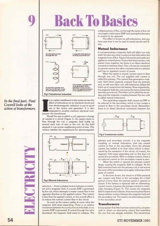
Fig.1 Transformer lnduction
1
n an earlier installment in this series we saw the
effect of inductance on an electrical circuit and
how electromagnetic induction is put to good
use in the motor and generator. It is also
employed in another common electrical com-
ponent: the transformer.
Recall the way in which a coil opposes a change
of current in a circuit (Figure 1). As current starts to
flow through the coil, a magnetic field builds up
around each turn of wire in the coil. As this field
expands it cuts across neighboring tums of wire. This
motion satisfies the requirement for electromagnetic
(a) R1
+
T
- '-
TRANSFORMER
PRJMARV SECONDARY
Lo----
R2
(b) RI
+
T
1
~,'- ,,, - ,,~
' '
''
"":o
•, R2
'----<>.....,>----',,__:,.~, , '
.....___ ,' / ..,...__
... , ,,
Fig.2 Mutual lnductance
induction - there is relative motion between a conduc-
tor and a magnetic field: A counter EMF is generated
by the coi!, which attempts to make current flow in the
opposite direction to the applied current. This current
is less than the applied current, so the overall effect is
to reduce the normal current flow in the circuit.
As soon as the current settles at sorne value the
magnetic field stops expanding. There is no relative
movernent between the conductors and the field,so no
counter EMF is generated. If current through the coil is
decreased, the magnetic field starts to collapse. The
collapsing lines of flux cut through the turns of the coil
once again, inducing an EMF and causing the decrease
in current to be opposed.
The effect is known as self-inductance, and you
have seen how it can be used in tuned circuits and fil-
ters.
Mutual lnductance
A coil generating a magnetic field will affect not only
itself, but also any other conductor that falls within the
magnetic lines of flux. Figure 2 shows this principie as it
applies to a transformer.Notice that there are two coils
placed clase together, but there is no direct electrical
connection between them. One coil can be connected
to a power source; the other connects only to a resistor
and has no apparent source of power.
When the switch is closed, current starts to flow
through one coil. The coi! supplied with current is
called the primary.This current flow generates a mag-
netic field which expands outward frorn the primary
and, as with any other coi!, self-inductance delays the
build-up of current from the battery. More importantly,
the magnetic field also cuts across the turns ofwire that
form the second coil. This latter coi! is called the secon-
dary and the magnetic coupling between the two coils
is called mutual inductance.
The expanding magnetic field causes an EMF to
be induced in the secondary, which in turn causes a
current to flow in the secondary circuit. Remember,
there is no direct electrical connection between the
Fig.3 Transformer action
primary and secondary circuits; it is the magnetic
coupling, or mutual inductance, that has caused
current to flow in the secondary. Once the primary
current has settled at its final value (which is deter-
mined by the resistance of the circuit, of course), the
magnetic field stops expanding and no flux lines cut
across the secondary. With no relative motion, there is
no induced current so the secondary current is zero.
When the switch is opened the primary current
drops, causing the magnetic field to collapse. As the
field contracts back into the primary coil, it cuts across
the turns of the secondary once again, inducing a short
pulse of current.
In the form shown, the circuit is of little practica!
use: current only flows in the secondary for a brief
period of time when the primary switch is opened or
closed. If the battery is replaced with an alternating·
current source, however, the primary current is contin-
ually changing {Figure 3). This causes the magnetic
field to expand and collapse, thus ensuring that there is
always relative motion between the magnetic field and
the secondary coil. The result is an alternating current
in the secondary circuit.
Transfonners
It may appear that little has been achieved by using two
coils to obtain an alternating current that resembles
the one that was alref,ldY available. The transformer
ETI NOVEMBER 1991
2. 120VAC~
(RMS) t._____::]
(a) TURNS RATIO = 1:1
~
120V ~
( b) TURNS RATIO = 1:2
~
120V L___--=r
(e) TURNS RATIO= 2:1
100
TURNS
~
e_µv
~
e_yv
Fig.4 Voltage step up and step down
has many practica! uses, however. one of the most
common being to change a low voltage into a high vol-
tage or vice versa.
Recall that when rnagnetic induction is taking
place the induced voltage can be increased by passing
a longer length of conductor through the magnetic
field. In a transformer a conductor can be lengthened
by increasing the nurnber of turns Referto Figure 4. At
Athe primary supply voltage is 120Vand each winding
has 100 turns. The secondary output voltage is also
120V. At B the secondary v.inding has 200 tums; the
number of turns has been doubled and the output vol-
tage has also doubled. At C the secondary winding has
been reduced to 50 tums. With the secondary having
half the number of tums of the primary, the output vol-
tage is half of the input voltage.
Figure 5 shows the effecr ofvarying the number of
turns in the primary winding of the transformer. It
should be fairly clear from the diagrams that it is the
ratio of the number ofturns that determines the output
~
120V L___--=r
(a) TURNS RATIO= 1:1
~
120V L___--=r
( b) TURNS RATIO= 2:1
~
120V L___--=r
( e ) TURNS RATIO = 1:2
~
C__µºv
~
~V
100
TURNS
Fig.5 Turns ratio of a transformer
ETI NOVEMBER 1991
voltage. If the primary and secondary have the same
number of turns,whether 50,100,or 1,000, the output
voltage will equal the input voltage. Whenever the sec-
ondary has a greater number of turns than the pri-
mary, the output voltage will be higher; when it has
fewer turns the output will be lower. The ratio ofsecon-
dar)i turns to primary turns may be used to calculate
the output voltage if the supply voltage is known,
because the prirnary to secondary voltage ratio is
equal to the primary to secondary turns ratio (Figure
6).
When the secondary voltage is higher than the
primary voltage, the transformer is called a step-up
transformer. When the secondary supplies a lower vol-
tage than that connected to the primary, it is called a
step-down transformer. Both types are used extens-
ively in many applications, from small radio receivers
to power stations.
LET:
Ep = PRIMARY VOLTAGE
Es= SECONDARY VOLTAGE
Np = NUMBER OF PRIMA AY TURNS
Ns= NUMBER OF SECONDARY TURNS
Ep = Np OR Es = Ns
es "Ns EP Nii
EXAMPLE:
200
TURNS
cr.:
C__J;Jª?
TURNS RATIO= Ns = 1000 = 5
Nii 2oO
Es = 5, THEREFORE Es= 5 X Ep = 5 X 120V
Ep
Es =600V
Fig.6 Turns ratio calculations
Practical
Transformers
In practice, rhóst transformers
are more tJian simply two coils
of wire placed next to each
other. ~ have already seen
that pla ng an iron core inside -
a coil increases the coil's
inductance. Winding the pri-
mary and secondary of a trans-
former around such a core
increases the magnetic coup-
ling between the two windings,
and Figure 7 shows sorne ways
in which the coupling can be
achieved. The shell core is by
far the most usual arrange-
ment, with a plastic bobbin
being fitted over the centre of
the coré to hold the windings.
OPENCORE
CLOSED CORE
SHELL CORE
Magnetic lines of flux tra-
vel far more easily in an iron
core than they do through air,
so the core concentrates the
flux, ensuring that as much as Fig.7 lron core transformer construction
possible passes through the secondary coi! instead
being lost to the outside of the transformer. This
improves the efficiency of the transforrner; we shall see
sorne other important factors that affect efficiency
55
3. ••
56
POWEA
STATION
FAOTOAIES
HEAVV
INDUSTRV
500KW
Fig.8 Power distribution
shortly.
Having seen how a transformer steps voltages up
and clown, it is appropriate to examine sorne reasons
for wanting to do this. Figure 8 shows a simplified
arrangement of a power distribution system. Assume
that the generators at the power station have an out-
put voltage of llOOOV (llkV). Many large factories
take their power supply at this leve! to run the heavy
machinery that they use. In the diagram,a large indus-
trial centre requiring 500,000 watts of power is located
100 miles from the generating station, so it would
seem logical to just run cables to carry the required
11kV from one place to the other. As you can see, this
has not been done; instead, two transformers have
been installed so that the long-distance transmission
line operates at the much h~her voltage of 132kV. The
reason for this is power loss.
We know that all caoles have a certain amount of
resistance and that the onger the cable the higher the
resistance. Also if c:urre1rt flows through any reststance,
power is dissipated as neat. Assume that the 100-mile
run of cables in our diagram has a total resistance of
100 ohms. It is possible to calculate the current flowing
in the lines, because the voltage and power consump-
tion are known (see Figure 9). The formula for power
(a) 132KV SVSTEM
P = 500KW
E = 132KV
SO 1 = P = 500 = 3.79A
E" m
LINE POWER LOSS .= 1
2
R = 3.792
x100 = 1436W
( b) 11 KV SVSTEM
P = 500KW
E= 11KV
SO 1 = P = 500 = 45,5A
E" 11
R = 100R
LINE POWER LOSS = 1
2R = 45.52 x 100 = 207025W
Fig.9 Transmission line power loss
a)132kV system b) 11 kV system
dissipation, 12R, shows that with a fixed value of resist-
ance the power varies with the square of the current.
Power loss in the line is just under 1.5kW.
To see what would happen if the same lines were
used to carry power at llkV, repeat the calculation
with the new value for voltage. To obtain the same
amount of powerwith a lowervoltage requires a higher
current, so the line current has increased many times.
The line resistance, however, is the same, which has
resulted in a power loss of over 200kW. To reduce the
power loss while using the lower voltage would require
cables with a much lower resistance. Such cables cost
more,are harder to work with,and are heavier;heavier
cables imply heavier support towers, which will also
cost more. It is for this reason that long-distance power
lines use such high voltages - to keep the current, and
hence the power loss, as low as possible.
The transforrners used for power distribution can
be huge - sorne are the size of a house. At the other
end of the scale are the transformers used in domestic
radio and television receivers. These represent
another reason for steppingAC voltages up and down.
A typical transistorized radio receiver requires about
10 to 20Vanda transformer can be used to convert the
incoming 120 or 240V supply to the required leve!.
120V~
['~'
c6V3
~,..
120V~ 15V
10V
OV
Fig.10 Multiple secondary windings
Many transforrners have more than one secon-
dary (Figure 10). A typical valve-type transmitter, for
example, requires 300 to 400V and a separate 6.3V
supply to light the valve heaters. Using a transformer
with two secondary windings is much less expensive
than employing two separate units;it also saves a great
deal of space.
(a ) SERIES AIDING CONNECTION
~o:
..-I
·
Jv
~ 20V -
( b) SERIES-OPPOSING CONNECTION
Fig.11 Transformer phasing a) series aiding
connection b) series opposing connection
Another method that can be used to save costs is
to tapa secondary winding.This enables a single wind-
ing to supply severa! different voltages,so long as each
can share the same ground, or common, point. The
tapped winding behaves in the same way as two separ-
ETI NOVEMBER 1991
4. '¡ :J11
1
(.)
- ..
-10V ..
..
- V
:J111 20V
(
- .
+IOV ·.
- •.•
(b)
- (
+IOV
-
:J11
1
.
. .
·.·
20V
..
..
- •' 1
V
- OY
-
Fig.12 Phase splitter transformer
ate windings connected togeüier v;ould behave.
An important consideration oi the output vol-
tages is that of phase. Consider the transfonner con-
nections shown in Figure 11. The dots ar one end of
each secondary winding are often used ro indicate
phase. They show that when the maoKed end of one
secondary is positive with respecti,·e rn its other end,
the marked end of the second ~ind:ng u.ill also be posi-
tive with respect to its other end. 'ith a series-aiding
connection the two voltages corr.'c'ne in phase, giving
an output voltage equal to the su'.Tl of the secondary
voltages. With a series-oppos~ng connection, the vol-
tages combine 180º out of phase a:id so tend to cancel
each other.
The ability of a n-ansfo:mer ro give a reverse
phase output makes its usefU.: ;;-i sorne amplifier cir-
cuits which require two signa:s 180' out of phase with
each other. Figure 12 sho·s :.:O<.' a transformer with a
centre-tapped secondary ca!": °::)e used in this way; it is
often referred to as a p!:oasesplitter transformer.
Assume thatwith the prür.ar', cJITent flowing as shown
in A, the secondary de elo;Js c'1 EMF of 20V with the
top end of the coi! bei'1g :1egc:i·e and bottom end posi·
tive. Because the centre rap is connected to a common,
zero volts, point. the :o;:i is -10 and bottom is +10
volts. When the prima.}· c.rrrent changes direction, as
shown in B, the seco:ida.!y polarity also reverses. The
centre tapis still grou:1ded. leaving the top end at +10
and the bottom end ar - 10 volts. The two AC outputs
are, therefore. 180º out of phase.
lmpedance Matching
So far, we have seen hou. the magnetic field generated
by the primary current induces a current into the sec-
ondary. The situation is slightly more complex than
this, however. because the current flowing in the sec-
ondary creates its ou.n magnetic field which affects the
primary.
The field generated by the secondary winding is
of such a polariri,; that it opposes the primary magnetic
field, thus reducing rhe total magnetic flux. This reduc-
tion of flux reduces rhe self- inductance of the primary,
which in tum reduces the counter-EMF generated by
the primary u.inding. With less counter-EMF in the pri-
ETI NOVEMBER 1991
mary, its inductive reactance is lowered.
The result of this interaction of magnetic fields is
that when more current is drawn from the secondary,
current in the primary increases. Current is inversely
proportional to impedance (by Ohm's Law), so
another way of stating the situation is to say that if the
load impedance on the secondary is decreased, the
impedance seen by the source driving the primary will
also decrease. The transformer thus reflects any
impedance change.
The ratio of primary to secondary impedance is
determined by the tums ratio of the transformer (see
Figure 13). Notice that the impedance varíes with the
square of the turns rario, unlike voltage which varíes
directlywith the turns ratio. In the example shown, any
circuit driving the primary of the transformer would
see an impedance of 800R.
Thus,the transformer can be used to connect two
circuits together which are of greatly differing imped-
ances. A typical use of an impedance matching trans-
former is in an audio amplifier.Many amplifier circuits
require a load impedance of severa[ thousand ohms
(forreasons which are outside the scope of this article).
Most loudspeakers have an impedance of between 3
and 16R, so a transformer is used to match the source
to the load.
LET:
Zs = IMPEDANCE AT SECONDARY
Zp = 'REFLECTED' PRIMARY IMPEDANCE
~ = (t:!e)2 OR ~ = (11!!!)2
Zs Ns Zp Np
EXAMPLE:
~ = (t:!P)2 = (500)2 = 100
Zs Ns 50
,.. SOZp =Zsx100 =800R
Fig.13 [mpedance matching
Trad*sformer Effici.~ncy
Earlier, itwas mentioned that the voltage-to-tums ratio
formula applied to a perfect transformer. In practice
there are sorne power losses in a transformer, as with
any other component.
First, there is the resistance of the wire used for
the primary and secondary windings. The resistance
contributes nothing to the magnetic field and con-
sumes power according to the usual 12R power for-
mula. Such power loss is often called copper loss
(because the windings are copper).
Second, for 100% efficiency every line of flux gen-
erated by the primary winding must cut across the sec-
ondaiy winding. The iron core helps to concentrate
magnetic flux where it is needed, but it is impossible to
prevent any leakage of magnetic flux. Again, energy
used to generate magnetic flux that <loes not cut the
secondary winding is wasted.
Third is a property called hysteresis loss. The
magnetic domains in the iron core are continually
being polarized first one way and then the other by the
alternating current in the primary. Sorne energy is
required to keep re-aligning these domains.
57
5. ••
Finaly, there is loss due to eddy currents. We
know that when a magnetic field cuts a conductor a
current is induced. Without this reaction it would not
be possibe for the transformer to work. The iron core
also forms a good conductor of electrons. and the
magnetic field induces srnall currents in the core,
These are called eddy currents, and power is used up in
the form of heat. Eddy currents are minimized by mak-
ing the iron core laminated rather than solid.The lami-
nated core consists of severa thin iron sheets which
are bonded together with an insulating material. Eddy
currents are thus confined to each lamination and can-
not flow through the low resistance of a single, large
core.
Even with ali these losses, most transformers are
around 90 to 95% efficient, which means that the
theoretical calculations are accurate enough for ali but
the most demanding of applications.
Conclusion
We have now come to the end..Q.f.pur examination of
basic electrical circuits. This series has, of necessity,
been a somewhat condensed course, and if you want
to study basic principies in more detail the Basic Elec-
tricity course by Van Valkenburgh, Nooger & Neville,
!ne is highly recommended. This course is in five parts
and obtainable from many public libraries. Also
recommended are Heathkit's OC Electronics and AC
Electronics courses; these include parts packages for
you to perform experiments that help reinforce your
knowledge with practica examples.
( o )COPPER LOSS
R is interna! resistance
of primary winding
power loss = 1
2
R
(e) HYSTERESIS LOSS
-
Magnetic domalns
mu.st continually
fe--align ihemselves
Fig.14 Transformer losses
( b ) FLUX LEAKAGE
.., ,,
.:..::"[
!: :
' 1
: '
___.__,, '
Flux lines which do not
cut secondary represent
power wasted
( d ) EOOY CURRENTS
Flux lines cut iron core
and induce small currents
PCB & SCHEMATIC CAD DIGITAL SIMULATION ANALOGUE SIMULATION SMITH CHART CAD
EASY-PC [98
• Design Sin_gle sided, Double
sided and Multilayer boards.
• Provides Surface Mount
support.
•Standard output includes
Dot Matrlx / laser / lnkjet
printers Pen Plotters
Photo-plotters and NC Drill.
eAward Winning EASY-PC is
in use In over 9000
installations in 50 Countries
World-Wide.
e Runs on PC/XT/AT/286/386
with Herc, CGA, EGA, VGA.
• Superbly Easy to use.
• Not Co v Protected.
See us at DES, Stand 1214
8-11 Oct.
PULSAR [195
•At last! A full featured Digital
Circult Simulator for less
than t1000!
•Pulsar allows you to test your
logic designs without the
need for expensive test
equipment.
• Catch glitches down to a pico
second per week!
e lncludes 4000 Series CMOS
and 74LS Libraries.
•Runs on
PC/XT/AT/286/386/486 with
EGA or VGA. Hard disk
recommended.
• Not Copy protected.
ANALYSER 111 [195
/ ('. /
..._¡ . ~ ........
'
'
1
,, . 1
'·..:,.
'
.
'~.
•, 1
1
,......:':"
±-
_
-,_-_
-_
_
-
.----:.
::----~
eNEW P.OWerful ANALYSER 111
has full graphical output.
• Handles R's,L's,C's, BJT's,
FET's, OP-amp's, Tapped and
untapped Transformers, and
Microstrip and Co-axial
Transmission Unes.
•Calculates Input and Output
lmpedances, Gain and Group
Delay.
• Covers 0.001 Hz to >1OGHz
•Runs on
PC/XT/AT/286/386/486 with
EGAorVGA.
• Not Copy protected.
Number One Systems Ltd.
The Electronics CAD Specialists
Z-MATCH 11 [195
•Z-MATCH 11 takes the
drudgery out of RF matching
probfems and includes many
more features than the
standard Smith Chart.
• Provldes qulck accurate
solutions fo many matching
problems using transmlsslon
line transformers, stubs,
discrete components etc.etc..
• Supplled with comprehensive
user instructions lncluding
many worked examples.
eRuns on PC/XT/AT/386/486,
CGA,EGA,VGA
• Not Copy Potected
See ús at Desk-Top CAD
Stand 137, 5-7 Nov.
REF: ETI, HARDING WAY, SOMERSHAM ROAD, ST.IVES, HUNTINGDON, CAMBS, PE17 4WR, ENGLAND.
Telephone: 0480 61778 (7 lines) Fax: 0480 494042 lnternational: +44-480-61778 Fax: +44-480-494042
For full info' please Phone, Fax or Write . ACCESS, AMEX, MASTERCARD, VISA Welcome.
58 ETI NOVEMBER 1991
![120VAC~
(RMS) t._____::]
(a) TURNS RATIO = 1:1
~
120V ~
( b) TURNS RATIO = 1:2
~
120V L___--=r
(e) TURNS RATIO= 2:1
100
TURNS
~
e_µv
~
e_yv
Fig.4 Voltage step up and step down
has many practica! uses, however. one of the most
common being to change a low voltage into a high vol-
tage or vice versa.
Recall that when rnagnetic induction is taking
place the induced voltage can be increased by passing
a longer length of conductor through the magnetic
field. In a transformer a conductor can be lengthened
by increasing the nurnber of turns Referto Figure 4. At
Athe primary supply voltage is 120Vand each winding
has 100 turns. The secondary output voltage is also
120V. At B the secondary v.inding has 200 tums; the
number of turns has been doubled and the output vol-
tage has also doubled. At C the secondary winding has
been reduced to 50 tums. With the secondary having
half the number of tums of the primary, the output vol-
tage is half of the input voltage.
Figure 5 shows the effecr ofvarying the number of
turns in the primary winding of the transformer. It
should be fairly clear from the diagrams that it is the
ratio of the number ofturns that determines the output
~
120V L___--=r
(a) TURNS RATIO= 1:1
~
120V L___--=r
( b) TURNS RATIO= 2:1
~
120V L___--=r
( e ) TURNS RATIO = 1:2
~
C__µºv
~
~V
100
TURNS
Fig.5 Turns ratio of a transformer
ETI NOVEMBER 1991
voltage. If the primary and secondary have the same
number of turns,whether 50,100,or 1,000, the output
voltage will equal the input voltage. Whenever the sec-
ondary has a greater number of turns than the pri-
mary, the output voltage will be higher; when it has
fewer turns the output will be lower. The ratio ofsecon-
dar)i turns to primary turns may be used to calculate
the output voltage if the supply voltage is known,
because the prirnary to secondary voltage ratio is
equal to the primary to secondary turns ratio (Figure
6).
When the secondary voltage is higher than the
primary voltage, the transformer is called a step-up
transformer. When the secondary supplies a lower vol-
tage than that connected to the primary, it is called a
step-down transformer. Both types are used extens-
ively in many applications, from small radio receivers
to power stations.
LET:
Ep = PRIMARY VOLTAGE
Es= SECONDARY VOLTAGE
Np = NUMBER OF PRIMA AY TURNS
Ns= NUMBER OF SECONDARY TURNS
Ep = Np OR Es = Ns
es "Ns EP Nii
EXAMPLE:
200
TURNS
cr.:
C__J;Jª?
TURNS RATIO= Ns = 1000 = 5
Nii 2oO
Es = 5, THEREFORE Es= 5 X Ep = 5 X 120V
Ep
Es =600V
Fig.6 Turns ratio calculations
Practical
Transformers
In practice, rhóst transformers
are more tJian simply two coils
of wire placed next to each
other. ~ have already seen
that pla ng an iron core inside -
a coil increases the coil's
inductance. Winding the pri-
mary and secondary of a trans-
former around such a core
increases the magnetic coup-
ling between the two windings,
and Figure 7 shows sorne ways
in which the coupling can be
achieved. The shell core is by
far the most usual arrange-
ment, with a plastic bobbin
being fitted over the centre of
the coré to hold the windings.
OPENCORE
CLOSED CORE
SHELL CORE
Magnetic lines of flux tra-
vel far more easily in an iron
core than they do through air,
so the core concentrates the
flux, ensuring that as much as Fig.7 lron core transformer construction
possible passes through the secondary coi! instead
being lost to the outside of the transformer. This
improves the efficiency of the transforrner; we shall see
sorne other important factors that affect efficiency
55](data:image/gif;base64,R0lGODlhAQABAIAAAAAAAP///yH5BAEAAAAALAAAAAABAAEAAAIBRAA7)