Powerful Google developer tools for immediate impact! (2023-24 C)
Applied motion products regen clamp
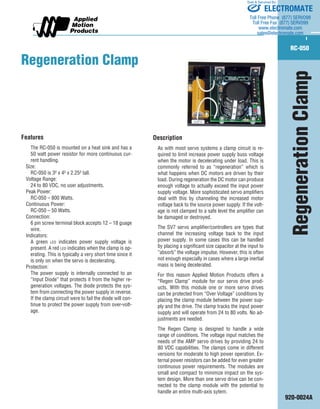
1. RC-050
920-0024A
Description
As with most servo systems a clamp circuit is required to limit increase power supply buss voltage when the motor is decelerating under load. This is commonly referred to as “regeneration” which is what happens when DC motors are driven by their load. During regeneration the DC motor can produce enough voltage to actually exceed the input power supply voltage. More sophisticated servo amplifiers deal with this by channeling the increased motor voltage back to the source power supply. If the voltage is not clamped to a safe level the amplifier can be damaged or destroyed.
The SV7 servo amplifier/controllers are types that channel the increasing voltage back to the input power supply. In some cases this can be handled by placing a significant size capacitor at the input to “absorb” the voltage impulse. However, this is often not enough especially in cases where a large inertial mass is being decelerated.
For this reason Applied Motion Products offers a “Regen Clamp” module for our servo drive products. With this module one or more servo drives can be protected from “Over Voltage” conditions by placing the clamp module between the power supply and the drive. The clamp tracks the input power supply and will operate from 24 to 80 volts. No adjustments are needed.
The Regen Clamp is designed to handle a wide range of conditions. The voltage input matches the needs of the AMP servo drives by providing 24 to 80 VDC capabilities. The clamps come in different versions for moderate to high power operation. External power resistors can be added for even greater continuous power requirements. The modules are small and compact to minimize impact on the system design. More than one servo drive can be connected to the clamp module with the potential to handle an entire multi-axis sytem.
Features
The
RC-050 is mounted on a heat sink and has a 50 watt power resistor for more continuous current handling.
Size:
RC-050 is 3² x 4² x 2.25² tall.
Voltage Range:
24 to 80 VDC, no user adjustments.
Peak Power:
RC-050 – 800 Watts.
Continuous Power:
RC-050 – 50 Watts.
Connection:
6
pin screw terminal block accepts 12 – 18 guage wire.
Indicators:
A
green led indicates power supply voltage is present. A red led indicates when the clamp is operating. This is typically a very short time since it is only on when the servo is decelerating.
Protection:
The
power supply is internally connected to an “Input Diode” that protects it from the higher regeneration voltages. The diode protects the system from connecting the power supply in reverse. If the clamp circuit were to fail the diode will continue to protect the power supply from over-voltage.
Regeneration Clamp
Regeneration Clamp
ELECTROMATE
Toll Free Phone (877) SERVO98
Toll Free Fax (877) SERV099
www.electromate.com
sales@electromate.com
Sold & Serviced By:
2. RC-050
920-0024A
Technical Specifications
Circuit Diagram:
The regeneration circuit is designed to provide a wide
range of voltage clamping operation with a simple and
reliable design. The block diagram gives a simplified view
of the circuit design showing the major parts.
Terminal Block:
A 6 connection terminal block provides easy connection
access to the clamp. The terminal are designed for wire
sizes from 12 – 28 AWG.
Input Diode:
The input diode provides over-voltage and reverse volt-age
protection. If the input power supply is connected in
reverse this diode will prevent failure. During over-voltage
conditions the diode blocks the higher regeneration volt-age
from feeding into the input power supply. The input
is designed to handle 20 amps continuous (RC-050) with
peaks greater than 100 amps.
Internal Power Resistor:
For moderate power operation this may be all that is
required for safe operation. This resistor is designed to
“sink” up to 8 amps when using an 80 volt power supply,
but only 2.5 amps when using a 24 volt supply. Larger
power resistors can be added to the circuit by connecting
between the “R1” and the “R2” terminals.
Filter Capacitor:
To smooth out operation and allow the “Clamp” to work
at a low switching frequency a large capacitor is added
across the voltage output.
Over-Voltage Sense Circuit:
This part of the clamp senses when on over-voltage oc-curs.
When the “Vout” exceeds the “Vin” by approximate-ly
1.2 volts the clamp will turn on. When “Vout” drops to
about 1 volt below “Vin” the clamp turns off.
Clamp MOSFET:
At the heart of the circuit is a power MOSFET designed for
20 amp continuous operation with the RC-050 version.
Indicator LEDS:
A green led is used to indicate power supply input while a
red led is used to indicate when the clamp is on.
Example 1
A single servo drive is connected to the Regen Clamp mod-ule.
This design will work in most cases where the load is
primarily “Frictional” as opposed to “Inertial.”
Example 2
Two servo drives are connected to the Regen Clamp mod-ule.
This design will work in cases where the load has sig-nificant
“Inertial” content.
Regen
Clamp
RC-050
+
Vout
-
Vin
GND1
GND2
24-48
VDC
Power
Supply
-
+ SV7
Regen
Clamp
RC-050
+
Vout
-
Vin
GND1
GND2
24-48
VDC
Power
Supply
-
+ SV7
SV7 Drive#2
Drive#2 -
+
R1
R2
External Power
Resistor
10 Ohm 50W
Clamp MOSFET
Over Voltage
Sense Circuit
Power
Resistor
Input Diode
Terminal Block
Vin
GND1
GND2
Vout
R1
R2
Green LED
Power Indication
Red LED
Clamp Indication
3.7"
2.5"
4.00"
0.150"
0.125"
3.0"
2.175"
3.7"
0.875"
Dimensions
ELECTROMATE
Toll Free Phone (877) SERVO98
Toll Free Fax (877) SERV099
www.electromate.com
sales@electromate.com
Sold & Serviced By: