1. HSDC/HRDC SERIES
ISOLATED SYNCHRO/RESOLVER
TO DIGITAL CONVERTERS WITH
BUILT-IN-TEST & FORCE TEST
DESCRIPTION:
HSDC & HRDC Series are Miniature, Tracking Synchro
and Resolver to Digital Converters with programmable
resolution, 8/16 Bit data bus controls, continuous Built-In
Self-Test report, and forced angle test modes used for
functional validations on command for military and indus-trial
applications.
Models are available with either low cost differential in-puts,
or internally transformer isolated inputs for military
and the most demanding industrial applications.
No external signal conditioning, critical dynamics, front-end
components, or circuitry is required. The HSDC/HRDC
series accepts direct field voltage synchro or resolver in-puts,
and converts them into real-time, accurate, natural
binary digital data, available over an 8 or 16 bit
selectable databus. Provided as a complete plug-in solu-tion,
accuracy and performance is assured from the field
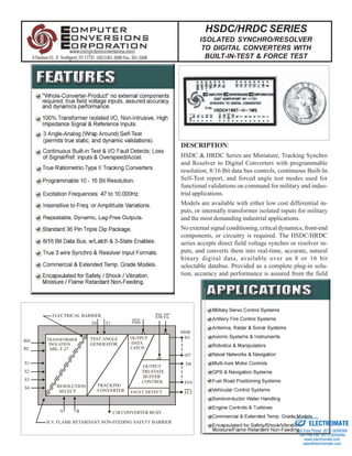
ELECTRICAL BARRIER
TRANSFORMER
ISOLATION
MIL-T-27
TEST ANGLE
GENERATOR
OUTPUT
DATA
LATCH
EM
OUTPUT
TRI-STATE
BUFFER
CONTROL
RESOLUTION
SELECT
A B
TRACKING
CONVERTER F AULT DETECT
H.V. FLAME RETARDANT NON-FEEDING SAFETY BARRIER
RH
RL
S1
S2
S3
S4
T0 T1
MSB
D1
D16
FLT
EL
INH.
C/B CONVERTER BUSY
D7
D8
Sold & Serviced By:
ELECTROMATE
Toll Free Phone (877) SERVO98
Toll Free Fax (877) SERV099
www.electromate.com
sales@electromate.com
2. signals to the digital user. All units are shipped with printed
test data.
All the high voltage components and transformers are
conformally coated and safely contained in a flame retar-dant
non-feeding encapsulated medium with a durable
through hole solder mounting for added containment and
resistance to shock and vibration, designed for MIL-STD-
202 environmental compliance.
The built-in-self-test provides a continuous report for loss
of reference, loss of input signal detect, over-speed, and
over-acceleration.
The Forced angle test mode allows the user to exercise the
converter on command (typical post power check), provid-ing
3 separate test angles verses run mode for normal op-eration.
The forced angle test provides benefits in both
user validation, and added diagnostics checks to the users
system.
The resolution is programmable 10-16 Bits wide, allowing
the user to select the resolution best suited to the operating
speed of any particular application.
Two tri-state enables are provided for low byte, high byte
select in 8 bit databus applications, or that may be tied to-gether
for any 16 bit or greater environment, or tied to ground
for continuous output used in discrete logic and display
applications.
The Inhibit input activates a buffered latch, and is internally
synchronized to the busy, assuring that only the most re-cent
valid data is stored and held on the outputs.
The HSDC/HRDC series are value-added whole converter
solutions, designed for easy and guaranteed trouble
free operation in the most demanding industrial and military
applications.
ISOLATION:
HSDC Series Transformer units feature unique, proven inter-nal
Scott-T micro-transformers. These micro-transformers provide
a true uncompromised galvanic isolation barrier between the
field wired reference and signal lines, and the user power sup-plies,
grounds and digital I/O.
The use of high impedance transformer isolated inputs assure
that signals are neither loaded or disturbed, and prevents inter-action
or impediment of grounding schemes respective of any
other apparatus sharing those lines.
This completely isolates the users circuitry from the all field
wiring, and any other systems that may be using these signals;
eliminating concerns over troublesome ground loops, separate
analog grounds, differing potentials, ground interjected spikes,
or ghostly field noise, that frequently cause computer system
instabilities.
Unlike external transformers that require significant real-es-tate,
and reduce converter accuracy by their inherent non-linearities,
and unlike hybrid-typical transformers that suffer poor
reliability because of their insufficient coil conductor size; the
HSDC's/ HRDC's internal micro-transformers provide a full
500VDC minimum breakdown voltage (high-pot), and the ac-curacy
is guaranteed for the whole synchro/resolver converter
system. 60Hz. inputs do not require additional size.
The unique micro-transformer design maintains a very
high impedance on the signal and reference inputs
regardless of any potential mode of failure. This
prevents the synchro-resolver signals and reference
(often feeding other users) from being adversely loaded
even in the unlikely event of failure.
THE CONVERTERS:
The HSDC Series are high performance, transformer iso-lated,
tracking, ratiometric; synchro/resolver to digital con-verters,
with internal three-point-angle self test, and built-in-
test; having internal solid state type two servo loops that
track the absolute position displacement, real-time, provid-ing
a crisp, virtually dynamic response, very high accuracy,
repeatability, and resolution that may even be
programmed while in motion, from 10 to 16 bits wide.
Because the converter employs the use of a type II servo
loop, the converter tracks the input angle real-time without
velocity lag error, the output data is dynamic, always fresh,
and continuously available. Only a minimum recoverable
lag may occur with extremely large excessive
accelerations, at which point the data is valid with mini-mum
lag and the fault output bit will be cleared to zero =
fault (automatically recovers).
This type II servo essentially closes its loop on the tangent
expressed as the ratio of the sin/cos of the input angle,
making this ratiometric conversion technique inherently in-sensitive
to absolute amplitude and frequency variations,
additionally; because the complex windings in the field
mounted sensors themselves expand and contract together,
though their absolute voltages may vary; the ratio of the
sensor outputs preserve the ratiometric accuracy, thereby
this ratio-conversion technique inherently provides the con-verter
with automatic temperature compensation on the field
mounted synchro/resolver sensor itself.
A small <1LSB hysteresis is injected into the loop to as-sure
that the data outputs are crisp, stable and
jitter-free, and to assure true 1 bit monotonicity (every single
bit state must be successively discernible, no jumping
of bits).
Data made available to the outputs is continuously updated
(tracking) without interruption; output data is stable,
Sold & Serviced By:
ELECTROMATE
Toll Free Phone (877) SERVO98
Toll Free Fax (877) SERV099
www.electromate.com
sales@electromate.com
3. SALIENT SPECIFICATIONS
Resolution 10 Bits 12 Bits 14 Bits 16 Bits
Accuracy +/-30' +/-8.5' +/-4'+1LSB +/-4'
-GAModels +/-4.5'+1LSB
-HAModels +/-21' +/-2.7' +/-2.6'
Tracking Rate 60Hz. 12.5 10 2.5 0.625
(RPS) 400Hz. 40 40 10 2.5
2.5Khz.+ 100 80 30 5
-HS models 2.5KHz.+ 200 200 50 10
Acceleration 60Hz. 770 295 20
400Hz. 12600 4500 610 124
for a 1 LSB lag 2,5KHz. 2500 9000 1620
1400 350 70
400Hz. 22000 5500 1100
2,5KHz.+ 160K 40000 8100
Step Responce 60Hz. 200ms. 360ms. 800ms. 1200ms.
180°input 2.5KHz.+ 95ms. 95ms. 150ms. 600ms.
Frequency Range 60Hz.units 47-1000Hz. 400Hz.units 360 - 2000Hz.
2.5Khz. units 2000-4.8Khz. Units to 10KHz. available
Reference Inputs 26VRMS into 90K ohms
115VRMS into 360K ohms
Signal Inputs 11.8VRMS L-L into 26K ohms Minimum L-L Balanced
26VRMS L-L into 26K ohms Minimum L-L Balanced
90VRMS L-L into 200K ohms Minimum L-L Balanced
Breakdown (volts) 500 VDC Minimum to Ground on Transformer Units
Power Supplies +5VDC, +5% (to 6VDC w/o damage)@ 25ma. max.
-12VDC, +5% (to 13VDC w/o damage)@ 25ma. max.
-15 Units: -15VDC +5% (to 16VDC w/o damage)@ 23ma. max.
Temperature 0°C to +70°C (-1 units)
(operating): -40°C to +85°C (-3 units)
(Storage): -55°C to +125°C
Notes:
1) Transformer isolation is highly recommended for all high voltage inputs, also when the signals are wired to more than one device or
system, where ground loops or field noise may be significant for bus concerns, radar and antenna applications, and absolutely mandated for
all Naval and most military concerns.
2) Accuracy applies over the operating temperature range, +/-10% amplitude and frequency variations, & +/-5% power supply variations.
3) Different input voltages and frequencies available, higher tracking rates and accuracy.
Notes:
1) Environmentals applies to and -3 suffix temp. variants.
2) *When conformally coated on PCB.
3) Guaranteed to meet these environmental test criteria.
MIL-STD-202 ENVIRONMENTALS
ENVIRONMENT METHOD CONDITION
Shock: 50G, 11 msec 213 A
Vibration: 10G, 2k Hz 204 C
Thermal Shock 107 A
Moisture 106* -
Salt Spray 101 B
Altitude 105 B
MIL-STD-202 ENVIRONMENTALS &
OUTPUT PHASING DETAILS
MIL-STD-1399 & MIL-S-20708
Designed for compliance with MIL-STD-1399 DOD Interface Standard for Shipboard Systems, Electric
Sold & Serviced By:
Power, AC Reference and Signal, Power and Isolation Mandates, and those of MIL-S-20708 for
Synchro’s.
ELECTROMATE
Toll Free Phone (877) SERVO98
Toll Free Fax (877) SERV099
www.electromate.com
sales@electromate.com
4. accurate, and always fresh up to the maximum tracking rate
of the converter.
NO EXTERNAL COMPONENTS:
Most other synchro/resolver converters even approaching
this size require numerous external components, allowing
the user to purchase a mere "core" product; no front end
signal conditioning, no isolation, no required critical dynam-ics
components. The user buys essentially a "core", and
must struggle with ever-compromising trimming/matching/
selecting of parts, then anticipate tuning/tweaking of many
external, interactive, precision, analog components; that de-termine
functionality, accuracy, and dynamic performance.
In many cases the user needs to have entire precision ana-log
component inventories, synchro/resolver test stations,
standards, bridges, ratio-transformers, simulators, and a
strong analog engineering and R&D staff just to confirm
operation under multiple static and dynamic conditions. What
starts out as a reasonably high accuracy converter "core" is
later degraded significantly based on the users choice (and
availability) of required external components, tweak-ability
and measured test results. Additionally, these "core" con-verters
need the added real-estate to accommodate the (typi-cally
over 30+) required external components.
Core converters need a analog intensive circuit board de-sign
that requires: persistence, multiple test and trim points,
and the art of analog designers wizardry' respective of the
converter, and the critical paths, placement, and interactive
considerations of the external analog circuitry required just
to make the converter work.
Entire front ends (signal conditioners) are often left out, core
converters will feature only 2 volt single ended inputs while
the field voltages are running with 7, 11.8 or even 90 volt
signals (external front end components will degrade accu-racy
and may impair functionality), no isolation is
provided, and external transformers occupying more real-estate
than the HSDC series "whole converter" alone may
be required.
The HSDC/HRDC converters are complete, isolated, "whole
converter" products, No External Components are Required.
No trial and error; accuracy and dynamic performance is
fully tested and assured to the system level, treated more
like a simpler digital component; use reasonable care in rout-ing
the signal inputs, apply power and your done. HSDC
converters are fully tested under static and dynamic condi-tions,
HSDC/HRDC SERIES
ISOLATED SYNCHRO/RESOLVER
TO DIGITAL CONVERTERS WITH
BUILT-IN-TEST & FORCE TEST
and printed test data with traceability is shipped with
every unit.
CONTINUOUS BUILT-IN SELF TEST (BIT):
The HSDC/HRDC series include a BIT/fault output that
operates autonomously in the background to report loss of
signal, loss of reference, over-speed, large angle step input
and tracking mode failures.
The BIT/fault output is logic level zero for fault indication.
FORCED ANGLE FOR SELF TEST:
In addition to not requiring any external components, the
HSDC/HRDC series is the first converter in the market-place
that also includes built-in "Forced" analog self-test
ability.
On systems employing functional test confirmations, the built-in
forced self-test features yield potentially huge cost savings and
save significant valuable real-estate that would otherwise be
required of added D-S/D-R converters and isolated switching
components to perform similar forced self-test (wraparound)
Sold & Serviced By:
ELECTROMATE
Toll Free Phone (877) SERVO98
Toll Free Fax (877) SERV099
www.electromate.com
sales@electromate.com
5. type capabilities, commonly expected if not required of newer
systems. Conventionally, other converters would require ex-pensive
external D-S/D-R converters, relays and/or other switching
circuitry, often suffering degraded reliability or compromising
isolation throughout.
PROGRAMMABLE RESOLUTION:
The converter resolution is programmable, to accommo-date
the highest resolution available respective of the maxi-mum
operating speed of the particular application.
The resolution is programmable for 10, 12, 14, or 16 Bits
per 360 degree input (1 part in 65,536), each resolution gra-dient
representing typically 4 times the maximum tracking
speed of the next.
This allows the user to position with very tight precision at
slow speeds, and still be able to report accurate real-time
data while slewing at very high speeds. A simple 2 bit com-mand
input (P1 &P2) allow the user to program the resolu-tion
from 10 to 16 bits, or, jumper these inputs
respective of the resolution desired for the application at
hand.
User circuitry may be employed to program a lower 10 bit
resolution when slewing a very high speeds, and increase
the resolution upward towards 16 bits when running at lower
operating speeds.
Because the Data is MSB left aligned, the user may con-figure
his program to expect 16 bit resolution always, for
complete independence from whatever resolution he is run-ning
in the actual application.
TIMING AND INTERFACE:
The output data changes respective of realized displace-ment
on the input angle and in proportion to speed. The
output data is monotonic, whereby the every 1 least signifi-cant
bit of change is realized on the output with no missing
counts. A 1-2 microsecond “Converter Busy” (C/B) pulse
is generated the instant the data output is being incremented/
decremented, and stabilized within 0.2 microseconds respec-tive
of the C/B’s leading edge.
Interface considerations range from monitoring the C/B, to
using the “Inhibit” (INH) signal input to latch the data on com-mand.
A low level inhibit occurring during a C/B will be ig-nored
until the new data is set on the outputs.
DATA TRANSFER ON DEMAND-LATCH INPUT
When the /INH. (Inhibit) input is cleared to zero; within 300 nsec.
all data bits are latched, and data is valid to be read. Release the
Inhibit line for 100 nsec. min. to assure that new data is trans-ferred
towards the buffered latch type output.
The INH line may also be used to capture real-time position data
synchronized to a time stamp, camera strobe, or to capture several
axis of data simultaneously on coordinated axis' control schemes.
ASYNCHRONOUS DATA TRANSFER -BUSY OUTPUT
Alternatively, the C/B (converter Busy) output may be used; it will
occur as fast as the max. specified tracking rate for the resolution
selected (up to every 2.0 Usec. at it's fastest rate depending on the
speed of the inputs changing ), (ex. 27 RPS at 14 bits = 2.26
Usec.), it will be active = busy (logic 1=H) for nominally 300 nsec.;
transfer data on the fallen edge.
For simple Display type devices, the converters will be free run-ning
and use of the inhibit or C/B line may not be required.
.25 to .75 Usec.
5.5 Usec. Min. Relative to:
0.15 Usec.
Busy Out
(CB)
Inhibit In.
(INH)
Øin/Øout
Data Valid Data Valid Data Valid
Sold & Serviced By:
ELECTROMATE
Toll Free Phone (877) SERVO98
Toll Free Fax (877) SERV099
www.electromate.com
sales@electromate.com
6. 3-STATE ENABLES & 8 OR 16 BIT BUS CONTROL:
ENH covers the 8 MSB's, ENL covers the 8 LSB's (least Signifi-cant
Bits), clear to zero (logic 0VDC = L=O), data will be active on
the bus within 150 nsec., for 16 Bit Bus tie both together for single
line control (may also be tied to Inhibit, wait 300 nsec. for every-thing),
if not used simply tie ENL and ENH to ground. The enable
lines must be high for 40 nsec. min. to assure the outputs are all
turned off of the bus.
PACKAGE:
The complete converter including internal transformers, and re-quiring
no external components, is provided in a standard 36 pin
triple-dip package, w/std. .020 dia. pins, on .100" centers, with a
low .43" H. profile. Comparable in size to non-isolated hybrids.
SAFETY AND CONSTRUCT:
All modules are encapsulated in an inert polymer that is self-extinguishing,
flame retardant to U.L. 94VO, and will not feed or
combust. Printed Circuit card material is flame retardant FR4,
assemblies are conformal-coated for moisture resistance. Trans-formers
are manufactured to MIL-T-27 and capable of with-standing
high-pot to 500VDC. Case is flame resistant glass filled
Diallyl Phthalate per MIL-M-14. Because all the high voltage
circuitry is encapsulated within the self-extinguishing and flame
retardant potting material; added protection is provided with re-spect
to the potential for component failure, shock and vibration,
and are suitable for the most severe industrial and military appli-cations.
HSDC/HRDC SERIES
ISOLATED SYNCHRO/RESOLVER
TO DIGITAL CONVERTERS WITH
BUILT-IN-TEST & FORCE TEST
Sold & Serviced By:
ELECTROMATE
Toll Free Phone (877) SERVO98
Toll Free Fax (877) SERV099
www.electromate.com
sales@electromate.com