

Recommandé
Recommandé
Contenu connexe
Tendances
Tendances (20)
Similaire à EDrive Actuators Vec Tac VT
Similaire à EDrive Actuators Vec Tac VT (12)
Plus de Electromate
Plus de Electromate (20)
Dernier
Dernier (20)
EDrive Actuators Vec Tac VT
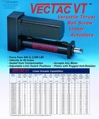
- 1. Precision Mechanical Products TM VVersatile Thrustersatile Thrust Ball ScrewBall Screw LinearLinear ActuatorsActuators A C T U ATO R S ® DRIVE For Application Support Call us Today at Fax: 860-953-0496 Tel: 860-953-0588 800-878-1157 Ball Screw Diameter (in) Linear Actuator Capabilities: (1) Intermediate lengths are available. (2) Lead accuracy is 0.003 in/ft; Backlash is 0.004 in max. Model Number Thrust Load Rated (lbf) Linear Velocity Max. (in/sec) Travel Length(1) Max. (in) Frame Size (in) Lead(2) (in) Ball Screw Max. (RPM) Torque @ Ball Screw Max. (in-lb) Dynamic Capacity per million inches (lbf) Motor Gearhead Frame Supported Max. (in) Unit Weight “U” Motor Mount (lb) Unit Weight “L” Motor Mount (lb) VT204-06 400 16 6 2.25 0.50 0.50 1,920 35 1,070 850 3.5 9.0 7.0 VT204-12 400 16 12 2.25 0.50 0.50 1,920 35 1,070 850 3.5 12.0 10.0 VT204-18 400 16 18 2.25 0.50 0.50 1,920 35 1,070 850 3.5 15.0 13.0 VT204-24 400 16 24 2.25 0.50 0.50 1,920 35 1,070 850 3.5 18.0 16.0 VT209-06 900 9 6 2.25 0.20 0.63 2,700 32 1,070 850 3.5 9.0 7.0 VT209-12 900 9 12 2.25 0.20 0.63 2,700 32 1,070 850 3.5 12.0 10.0 VT209-18 900 9 18 2.25 0.20 0.63 2,700 32 1,070 850 3.5 15.0 13.0 VT209-24 900 9 24 2.25 0.20 0.63 2,700 32 1,070 850 3.5 18.0 16.0 VT305-06 500 40 6 3.25 1.00 1.00 2,400 88 2,300 2,300 4.5 24.0 19.8 VT305-12 500 40 12 3.25 1.00 1.00 2,400 88 2,300 2,300 4.5 28.4 24.2 VT305-18 500 40 18 3.25 1.00 1.00 2,400 88 2,300 2,300 4.5 32.8 28.6 VT305-24 500 40 24 3.25 1.00 1.00 2,400 88 2,300 2,300 4.5 37.2 33.0 VT305-30 500 40 30 3.25 1.00 1.00 2,400 88 2,300 2,300 4.5 41.6 37.4 VT310-06 1,000 20 6 3.25 0.50 1.00 2,400 88 5,350 4,250 4.5 24.0 19.8 VT310-12 1,000 20 12 3.25 0.50 1.00 2,400 88 5,350 4,250 4.5 28.4 24.2 VT310-18 1,000 20 18 3.25 0.50 1.00 2,400 88 5,350 4,250 4.5 32.8 28.6 VT310-24 1,000 20 24 3.25 0.50 1.00 2,400 88 5,350 4,250 4.5 37.2 33.0 VT310-30 1,000 20 30 3.25 0.50 1.00 2,400 88 5,350 4,250 4.5 41.6 37.4 VT320-06 2,000 10 6 3.25 0.25 1.00 2,400 88 5,475 3,450 4.5 24.0 19.8 VT320-12 2,000 10 12 3.25 0.25 1.00 2,400 88 5,475 3,450 4.5 28.4 24.2 VT320-18 2,000 10 18 3.25 0.25 1.00 2,400 88 5,475 3,450 4.5 32.8 28.6 VT320-24 2,000 10 24 3.25 0.25 1.00 2,400 88 5,475 3,450 4.5 37.2 33.0 VT320-30 2,000 10 30 3.25 0.25 1.00 2,400 88 5,475 3,450 4.5 41.6 37.4 Dynamic Capacity per million revs (lbf) • Force from 400 to 2,000 LBf • Velocity to 40 in/sec • Sealed from Contamination • Accepts Any Motor • Adjustable Limit Switch Positions • Piston with Rugged Anti-Rotation ELECTROMATE Toll Free Phone (877) SERVO98 Toll Free Fax (877) SERV099 www.electromate.com sales@electromate.com Sold & Serviced By:
- 2. U-Parallel Offset Motor Configuration Rear Clevis Dimensions L-Inline Motor Configuration General Dimensions Note: DXF or DWG files are available at www.edriveactuators.com 2 Model A B C D E F G H J K L M N P Q VT204 3.50 1/2-20 0.63 2.25 1.13 1.25 4.84 1.88 1.63 7.25 1/8 3.44 0.50 0.75 1.13 VT209 3.50 1/2-20 0.63 2.25 1.13 1.25 4.84 1.88 1.63 7.25 1/8 3.44 0.50 0.75 1.13 VT305 4.50 3/4-16 0.88 3.25 1.75 1.40 7.03 2.47 2.38 9.63 1/8 3.97 0.75 1.25 1.88 VT310 4.50 3/4-16 0.88 3.25 1.75 1.50 7.03 2.47 2.38 9.63 1/8 3.97 0.75 1.25 1.88 VT320 4.50 3/4-16 0.88 3.25 1.75 1.50 7.03 2.47 2.38 9.63 1/8 3.97 0.75 1.25 1.88 VecTac VT U-Parallel Offset, L-Inline and Rear Clevis Dimensions •Web www.edriveactuators.com •Email info@edriveactuators.com •120 Vanderbilt Avenue •West Hartford, CT 06110 For Application Support Call us Today at Fax: 860-953-0496 Tel: 860-953-0588 800-878-1157 A C T U ATO R S ® DRIVE 200 400 600 800 1,000 1,200 1,400 1,600 1,800 2,000 0 1 10 100 1,000 Graph: Life Vs. Load VT204/VT209 VT305 VT310 Life vs Load B10Life(millionInches) Equivalent Load (lb) VT320 EQUIVALENT LOAD is the average force over the working stroke, weighted proportionately to the distance traveled. For constant force loads, the equivalent load is the same as the typical or average load. Where forces vary due to gravity, angle of actuator, acceleration and deceleration, friction, and changing dynamic loads at different positions, it is best to determine the equivalent load in order to most accurately pre- dict the B10 life of the actuator. F = L1(F1)3 +L2(F2)3 +L3(F3)3 +L4(F4)3 +.......Ln(Fn)3 Where: Fn is the calculated force for segment "n" with travel length of Ln and total travel L. Find the intersection of this value and the appropriate curve. The value on the scale to the left reflects the B10 life of the actuator. 3 L Note: DXF or DWG files are available at www.edriveactuators.com + .025 + .015 + .004 + .002 ELECTROMATE Toll Free Phone (877) SERVO98 Toll Free Fax (877) SERV099 www.electromate.com sales@electromate.com Sold & Serviced By:
- 3. 3 Model A B C D E F G H J K L M N P Q R S T U V W X VT2 1.31 2.63 3.25 2.38 1.19 5/16-18 0.63 3.84 0.75 0.38 1.75 0.88 2.25 0.25 0.34 0.69 1.89 3.78 2.63 5.25 0.50 4.22 VT3 1.88 3.75 4.50 3.38 1.69 3/8-16 0.75 5.78 1.00 0.50 2.63 1.31 3.25 0.25 0.41 0.94 2.52 5.03 3.50 7.00 0.75 6.28 Unit Mounting Dimensions Bottom Mount Dimensions Note: DXF or DWG files are available at www.edriveactuators.com Front Flange Dimensions Note: DXF or DWG files are available at www.edriveactuators.com Foot Mount Dimensions Note: DXF or DWG files are available at www.edriveactuators.com Trunnion Mount Dimensions Note: DXF or DWG files are available at www.edriveactuators.com ® DRIVE •Web www.edriveactuators.com •Email info@edriveactuators.com •120 Vanderbilt Avenue •West Hartford, CT 06110 For Application Support Call us Today at Fax: 860-953-0496 Tel: 860-953-0588 800-878-1157 A C T U ATO R S ® DRIVE ELECTROMATE Toll Free Phone (877) SERVO98 Toll Free Fax (877) SERV099 www.electromate.com sales@electromate.com Sold & Serviced By:
- 4. The products shown in this catalog are intended for industrial use only and should not be used to lift, support or otherwise transport people, unless written authorization is obtained. The information provided in this catalog is believed to be accurate and reliable. However, E•DRIVE assumes no responsibility for its use or for any errors that may appear in this document. This information in this publication is subject to change without notice. •Web www.edriveactuators.com •Email info@edriveactuators.com •120 Vanderbilt Avenue •West Hartford, CT 06110 © 2004 E•DRIVE Design, Inc. Printed USA 11/2004 How To Order: V T Frame Size (in): 2,3 Standard Stroke Length (in): Unit Mounting Option: MB Bottom Mount FF Front Flange MF Foot Mount TF Front Trunnion TR Rear Trunnion CR Rear Clevis Motor Position 1, 2, 3, 4 0 = Inline (refer to figure) 1 2 3 4 Base Number Options Special Capacity (lb): x100 Gearbelt Reduction: 00- Direct Coupled 10- 1:1 20- 2:1 Custom Length (in): 00.00 Model A B C D E F G H J K L M N P Q R S T U VT2 2.00 0.75 1/2-20 0.63 1.25 0.56 0.31 1.31 0.50 0.63 1.50 0.50 1.00 0.75 0.63 2.00 0.75 2.44 1.50 VT3 2.31 1.13 3/4-16 0.97 1.75 0.88 0.42 1.75 0.75 0.88 2.06 0.75 1.50 1.25 0.88 2.81 1.13 2.88 1.75 Rod End Options Spherical Rod Eye Rod End Options Female Eye Self-Aligning Coupler (1) Male Thread + .000 - .005 Configuration: L- In-Line U- Parallel Offset For Application Support Call us Today at Fax: 860-953-0496 Tel: 860-953-0588 800-878-1157 A C T U ATO R S ® DRIVE + .000 - .010 End Effector/Rod End: E Female Eye F Female Thread A Self-Aligning Coupler M Male Thread S Spherical Rod Eye Switch Type: A - Hall Sourcing PNP B - Hall Sinking NPN C - Reed N.O. Switch Qty: 0, 1, 2, 3, etc. N.C. Switch Qty: 0, 1, 2, 3, etc. (1) Zero backlash version also available ELECTROMATE Toll Free Phone (877) SERVO98 Toll Free Fax (877) SERV099 www.electromate.com sales@electromate.com Sold & Serviced By: