1. What is a Spanning Tree
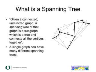
• “Given a connected,
undirected graph, a
spanning tree of that
graph is a subgraph
which is a tree and
connects all the vertices
together”.
• A single graph can have
many different spanning
trees.
2. Spanning Tree Protocol
• The purpose of the protocol is to have
bridges dynamically discover a subset of
the topology that is loop-free (a tree) and
yet has just enough connectivity so that
where physically possible, there is a path
between every switch
3. Spanning Tree Protocol
• Several flavors:
– Traditional Spanning Tree (802.1d)
– Rapid Spanning Tree or RSTP (802.1w)
– Multiple Spanning Tree or MSTP (802.1s)
4. Traditional Spanning Tree (802.1d)
• Switches exchange messages that allow
them to compute the Spanning Tree
– These messages are called BPDUs (Bridge
Protocol Data Units)
– Two types of BPDUs:
• Configuration
• Topology Change Notification (TCN)
5. Traditional Spanning Tree (802.1d)
• First Step:
– Decide on a point of reference: the Root
Bridge
– The election process is based on the Bridge
ID, which is composed of:
• The Bridge Priority: A two-byte value that is
configurable
• The MAC address: A unique, hardcoded address
that cannot be changed.
6. Root Bridge Selection (802.1d)
• Each switch starts by sending out BPDUs with a
Root Bridge ID equal to its own Bridge ID
– I am the root!
• Received BPDUs are analyzed to see if a lower
Root Bridge ID is being announced
– If so, each switch replaces the value of the advertised
Root Bridge ID with this new lower ID
• Eventually, they all agree on who the Root
Bridge is
7. Root Bridge Selection (802.1d)
Switch B Switch C
Swtich A
32678.0000000000AA
32678.0000000000BB 32678.0000000000CC
• All switches have the same priority.
• Who is the elected root bridge?
8. Root Port Selection (802.1d)
• Now each switch needs to figure out
where it is in relation to the Root Bridge
– Each switch needs to determine its Root Port
– The key is to find the port with the lowest
Root Path Cost
• The cumulative cost of all the links leading to the
Root Bridge
9. Root Port Selection (802.1d)
• Each link on a switch has a Path Cost
– Inversely proportional to the link speed
• e.g. The faster the link, the lower the cost
Link Speed STP Cost
10 Mbps 100
100 Mbps 19
1 Gbps 4
10 Gbps 2
10. Root Port Selection (802.1d)
• Root Path Cost is the accumulation of a
link’s Path Cost and the Path Costs
learned from neighboring Switches.
– It answers the question: How much does it
cost to reach the Root Bridge through this
port?
11. Root Port Selection (802.1d)
1. Root Bridge sends out BPDUs with a
Root Path Cost value of 0
2. Neighbor receives BPDU and adds port’s
Path Cost to Root Path Cost received
3. Neighbor sends out BPDUs with new
cumulative value as Root Path Cost
4. Other neighbor’s down the line keep
adding in the same fashion
12. Root Port Selection (802.1d)
• On each switch, the port where the lowest
Root Path Cost was received becomes the
Root Port
– This is the port with the best path to the Root
Bridge
13. Root Port Selection (802.1d)
Switch B Switch C
Swtich A
1 2
1 1
2 2
Cost=19 Cost=19
Cost=19
32678.0000000000AA
32678.0000000000BB 32678.0000000000CC
• What is the Path Cost on each Port?
• What is the Root Port on each switch?
14. Root Port Selection (802.1d)
Switch B Switch C
Swtich A
1 2
1 1
2 2
Cost=19 Cost=19
Cost=19
32678.0000000000AA
32678.0000000000BB 32678.0000000000CC
Root Port
Root Port
15. Electing Designated Ports (802.1d)
• OK, we now have selected root ports but we
haven’t solved the loop problem yet, have we
– The links are still active!
• Each network segment needs to have only
one switch forwarding traffic to and from
that segment
• Switches then need to identify one Designated
Port per link
– The one with the lowest cumulative Root Path Cost to
the Root Bridge
16. Electing Designated Ports(802.1d)
• Which port should be the Designated Port
on each segment?
Switch B Switch C
Swtich A
1 2
1 1
2 2
Cost=19 Cost=19
Cost=19
32678.0000000000AA
32678.0000000000BB 32678.0000000000CC
17. Electing Designated Ports (802.1d)
• Two or more ports in a segment having identical
Root Path Costs is possible, which results in a
tie condition
• All STP decisions are based on the following
sequence of conditions:
– Lowest Root Bridge ID
– Lowest Root Path Cost to Root Bridge
– Lowest Sender Bridge ID
– Lowest Sender Port ID
18. Electing Designated Ports(802.1d)
Switch B Switch C
Swtich A
1 2
1 1
2 2
Cost=19 Cost=19
Cost=19
32678.0000000000AA
32678.0000000000BB 32678.0000000000CC
Designated
Port
Designated
Port
Designated
Port
In the B-C link, Switch B has the lowest
Bridge ID, so port 2 in Switch B is the
Designated Port
19. Blocking a port
• Any port that is not elected as either a
Root Port, nor a Designated Port is put
into the Blocking State.
• This step effectively breaks the loop and
completes the Spanning Tree.
20. Designated Ports on each segment (802.1d)
Switch B Switch C
Swtich A
1 2
1 1
2 2
Cost=19 Cost=19
Cost=19
32678.0000000000AA
32678.0000000000BB 32678.0000000000CC
• Port 2 in Switch C is then put into the Blocking State because it is
neither a Root Port nor a Designated Port
✕
21. Spanning Tree Protocol States
• Disabled
– Port is shut down
• Blocking
– Not forwarding frames
– Receiving BPDUs
• Listening
– Not forwarding frames
– Sending and receiving BPDUs
22. Spanning Tree Protocol States
• Learning
– Not forwarding frames
– Sending and receiving BPDUs
– Learning new MAC addresses
• Forwarding
– Forwarding frames
– Sending and receiving BPDUs
– Learning new MAC addresses
23. STP Topology Changes
• Switches will recalculate if:
– A new switch is introduced
• It could be the new Root Bridge!
– A switch fails
– A link fails
24. Root Bridge Placement
• Using default STP parameters might result
in an undesired situation
– Traffic will flow in non-optimal ways
– An unstable or slow switch might become the
root
• You need to plan your assignment of
bridge priorities carefully
25. Bad Root Bridge Placement
Switch D
Switch C
Swtich B
32678.0000000000BB 32678.0000000000DD
32678.0000000000CC Switch A 32678.0000000000AA
Root
Bridge
Out to router
26. Good Root Bridge Placement
Switch D
Switch C
Swtich B
1.0000000000BB 0.0000000000DD
32678.0000000000CC Switch A 32678.0000000000AA
Alernative
Root Bridge
Out to active
router
Root Bridge
Out to standby
router
27. Protecting the STP Topology
• Some vendors have included features that
protect the STP topology:
– Root Guard
– BPDU Guard
– Loop Guard
– UDLD
– Etc.
28. STP Design Guidelines
• Enable spanning tree even if you don’t
have redundant paths
• Always plan and set bridge priorities
– Make the root choice deterministic
– Include an alternative root bridge
• If possible, do not accept BPDUs on end
user ports
– Apply BPDU Guard or similar where available
29. 8021.d Convergence Speeds
• Moving from the Blocking state to the Forwarding State
takes at least 2 x Forward Delay time units (~ 30 secs.)
– This can be annoying when connecting end user stations
• Some vendors have added enhancements such as
PortFast, which will reduce this time to a minimum for
edge ports
– Never use PortFast or similar in switch-to-switch links
• Topology changes tipically take 30 seconds too
– This can be unacceptable in a production network
30. Rapid Spanning Tree (802.1w)
• Convergence is much faster
– Communication between switches is more
interactive
• Edge ports don’t participate
– Edge ports transition to forwarding state
immediately
– If BPDUs are received on an edge port, it
becomes a non-edge port to prevent loops
31. Rapid Spanning Tree (802.1w)
• Defines these port roles:
– Root Port (same as with 802.1d)
– Alternate Port
• A port with an alternate path to the root
– Designated Port (same as with 802.1d)
– Backup Port
• A backup/redundant path to a segment where
another bridge port already connects.
32. Rapid Spanning Tree (802.1w)
• Synchronization process uses a
handshake method
– After a root is elected, the topology is built in
cascade, where each switch proposes to be
the designated bridge for each point-to-point
link
– While this happens, all the downstream switch
links are blocking
33. Rapid Spanning Tree (802.1w)
Root
Switch
Proposal
Switch
Agreement
Switch
Switch
DP
RP
34. Rapid Spanning Tree (802.1w)
Root
Switch
Proposal
Switch
Agreement
Switch
Switch
DP
RP
DP
RP
35. Rapid Spanning Tree (802.1w)
Root
Switch
Proposal
Switch
Agreement
Switch
Switch
DP
RP
DP
RP
DP
RP
36. Rapid Spanning Tree (802.1w)
Root
Switch
Proposal
Switch
Agreement
Switch
Switch
DP
RP
DP
RP
DP
RP
DP
RP
37. Rapid Spanning Tree (802.1w)
• Prefer RSTP over STP if you want faster
convergence
• Always define which ports are edge ports
38. Multiple Spanning Tree (802.1s)
• Allows separate spanning trees per VLAN
group
– Different topologies allow for load balancing
between links
– Each group of VLANs are assigned to an
“instance” of MST
• Compatible with STP and RSTP
40. Multiple Spanning Tree (802.1s)
• MST Region
– Switches are members of a region if they
have the same set of attributes:
• MST configuration name
• MST configuration revision
• Instance-to-VLAN mapping
– A digest of these attributes is sent inside the
BPDUs for fast comparison by the switches
– One region is usually sufficient
41. Multiple Spanning Tree (802.1s)
• CST = Common Spanning Tree
– In order to interoperate with other versions of
Spanning Tree, MST needs a common tree
that contains all the other islands, including
other MST regions
42. Multiple Spanning Tree (802.1s)
• IST = Internal Spanning Tree
– Internal to the Region, that is
– Presents the entire region as a single virtual
bridge to the CST outside
43. Multiple Spanning Tree (802.1s)
• MST Instances
– Groups of VLANs are mapped to particular
Spanning Tree instances
– These instances will represent the alternative
topologies, or forwarding paths
– You specify a root and alternate root for each
instance
45. Multiple Spanning Tree (802.1s)
• Design Guidelines
– Determine relevant forwarding paths, and
distribute your VLANs equally into instances
matching these topologies
– Assign different root and alternate root
switches to each instance
– Make sure all switches match region
attributes
– Do not assign VLANs to instance 0, as this is
used by the IST