1. V2 Nov 2015
DIGITAL IMAGE CORRELATION AND ITS
BENEFITS TO INDUSTRY
Ross Smith, Evan Guilfoyle and Karl Mackle
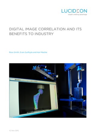
2. INTRODUCTION
Digital Image Correlation (DIC) is a non-contact,
non-interferometric measurement technique that
uses high-resolution machine-vision digital
cameras to accurately measure surface
deformation in two or three dimensions. This
measurement is presented graphically in a
number of ways such as a 2D strain map
overlaying the test specimen, or a 3D
displacement map showing the specimen surface
and how it moves throughout the test.
Early development of this technology began in
the mid-1980s in the mechanical engineering
department of the University of South Carolina.
Since then it has gone on to revolutionize
mechanical testing on both the macro and micro
scale.
The applications of DIC are vast, from eyeball
pressure testing to earthquake analysis; this
adaptable and highly capable system will
transform design, validation and testing methods
for anything from dental implants to wind
turbines.
THE PRINCIPLE OF DIC
The DIC system is based on the ability of high
resolution cameras to track a black and white
speckle pattern on the surface of an object as the
object deforms. The calibrated cameras take an
initial image before any deformation occurs and
uses this image as the reference, or start position,
for a variety of calculations. The cameras can
then record images at a defined rate throughout
a test; these are then processed by the computer
analysis software.
In the post-analyses the software divides the
reference image up into subsets. Each subset has
a pre-defined pixel size which can be changed
depending on the speckle size or type of analysis
required. A unique greyscale number is given to
each subset which is assumed to remain constant
throughout the deformed images. By using a
correlation equation the DIC software can track
these subsets across the various deformed
images by identifying the unique grey scale level
for each subset.
MAPPING
In order to calculate the correlation coefficient
the relative position of the deformed image to
the reference image needs to be calculated. The
software does this by forming a linear mapping
function which assumes the deformation on the
surface of the object follows the translation.
CORRELATION PRINCIPLE
Correlation equations are used to match the
original image subset to the subset in the
deformed image. There are numerous correlation
equations which are used depending on the
specific system software, all of which will yield
the same results. The correlation works by
matching the original subset to the deformed
subset with the highest accuracy possible.
To obtain the highest possible level of correlation
between the reference subset and the deformed
subset the sum of the square difference between
greyscale levels is minimized. By using the
following correlation equation the DIC can match
the original subset to the deformed subset with
an accuracy of greater than 0.01 pixels.
Correlation Co-efficient C
,
,
.
, 1,2
Where is the intensity distribution from the
reference image and ′ is the intensity
distribution from the deformed image at point .
INTERPOLATION
In order to achieve accurate correlations between
subsets the content of the subsets needs to be
examined in detail. The DIC software works by
converting the light intensity of each pixel into a
digital grey scale number ranging from 0 to 255.
This discrete data does not truly represent the
actual intensity distribution being recorded by
the cameras but rather provides a digital
approximation. To achieve a more continuous
intensity distribution a bilinear interpolation
technique is used.
Using this bilinear interpolation method the
computer system can analyze a more accurate
representation of the greyscale level that is
present on the object’s surface rather than a
digital map of what the camera’s sensors are
picking up. This, along with the correlation
equations, provides an extremely accurate
3. approximation of the surface deformation
occurring.
There are various other parameters which affect
the measurement accuracy of the DIC system.
These parameters can vary between tests and
need to be considered individually before each
test. In order to achieve reliable calculations, a
speckle size, speckle density, and subset size
need to be chosen in order to optimize the
software’s ability to calculate the various
equations explained above.
AUGMENTING TRADITIONAL TESTING
METHODS
DIC can be used to not only augment mechanical
testing, but transform it. Traditionally, in order to
examine strain, strain gauges are placed on the
surface of the specimen at points of interest.
However the deformation of heterogeneous
material, such as concrete with large aggregate
sizes, is very complex and the correct placement
of strain gauges can be hard to predict. As well
as this, for a large specimen, the number of strain
gauges required can grow very quickly. With DIC
every point on the specimen can be analyzed
quickly and easily. This can be of particular use in
much smaller scale samples with complex
topography and tribology where the effective
application of strain gauges may prove difficult.
Retrospective analysis can also be carried out,
allowing the user to add virtual extensometers,
line inspections and a host of other inspection
tools.
The ability to forego strain gauges and adhesive-
dependant measuring equipment offers a distinct
advantage to the DIC user. The surface is left
undisturbed and in full view. The slow motion
video capture software allows the user to see the
strain, crack propagation and failure modes of
the specimen at any point in time.
The convenient size of the system allows the
equipment to be set up in front of any test rig
while a voltage output from the test frame can be
connected to the system to add another layer of
analysis.
FLEXURAL STRENGTH TEST
A common application for DIC is in conjunction
with three point bend tests as illustrated below.
Traditionally the user has only been able to
determine the load at which the specimen
undergoes a specific level of deflection. DIC
gives the user the ability to perform an in-depth
analysis, examining the failure modes of the
specimen, where the maximum strain was located
and the force it took for cracks to begin to form.
The high resolution cameras coupled with the
advanced displacement calculating software offer
a level of crack detection that is impossible to
perform with the naked eye.
Figure 1. A specimen under Standard Load Test
Figure 2. A specimen under load with DIC
Figures 1 and 2 show the same three-point bend
test with and without DIC analysis. It can be
observed that in the first image the cracks appear
to only have begun to propagate, however the
DIC analysis shows that hairline fractures have
already occurred extending across fifty percent
of the specimen.
CHARPY TESTING
Perhaps the most common material test, the
Charpy test (or the V notch test), has been in
existence for over a century, with very little
change or improvement.
Traditionally designed to determine a material’s
notch toughness, the test relies on calculating the
energy absorbed by the specimen when struck
by a pendulum. As a result of widespread use
there is a compelling argument for as much data
to be extracted from the test as possible.
4. High speed DIC can be utilized for this purpose.
The strain at the notch tip can be quantified and
graphically plotted against time, allowing the user
to determine the existence of flaws in the
material that result in rapid propagation of
cracks.
TENSILE TESTING
Like the three point bend test, tensile testing has
traditionally been used to evaluate a very limited
number of variables, in this case, the Young’s
modulus of the material, the maximum elongation
and the reduction in area. However when
examining heterogeneous materials under
tension, DIC can give a whole new layer of
analysis.
The boundaries between materials in a specimen
are often the weakest points. As the specimen is
loaded DIC can be used to examine the strain
distribution across the specimen. This
information can be used to determine the likely
effect the composition of the specimen is having
on the material’s ultimate tensile strength. In
addition to this, the virtual extensometers
available in the analysis can quickly calculate the
elongation between any two points.
Figure 3. Tensile Test with DIC
Figure 3 shows an example of DIC being used to
determine the maximum strain developed in a
material under test as well as the maximum
elongation using a virtual extensometer.
COMPRESSION TESTING
As the DIC system uses displacement as the basis
for its calculation, it is of great benefit to
compression testing. Additional cameras can be
added to the system to allow a full field of view
of the specimen. This allows out-of-plane
displacement measurement at almost 360
degrees.
A problem often encountered during
compression testing is how to mitigate against
the deviation from true stress and engineering
stress caused by the phenomena known as
barrelling. Barrelling is the change in shape of the
specimen under load resulting in a larger contact
surface: thus energy is absorbed through friction
between the specimens and the articulating
surface. The use of full field optics such as DIC
allows for accurate calculation of the barrelling
profile. This can be used to compute the
Coulomb friction coefficient and thus calculate
deviation of the true stress from the engineering
stress.
A new dimension of compression tests can also
be performed on specimens of complex
geometry. Previously, finite element modelling
was required to accurately predict areas of high
strain under various loading conditions. Now,
with the DIC system, a finite element model level
of detail can be obtained in real loading tests,
allowing pre manufacture validation and quality
control along the entire manufacturing process.
FATIGUE TESTING
Fatigue testing is an essential part of mechanical
testing of any operational component. Often,
moving assemblies cannot be tested during
operation due to space constraints and
difficulties maintaining electrical connections.
Inconsistent operating cycles and contact zones
between components can cause difficulties in
predicting fatigue behaviour and stress
concentrations. Full field measurement
capabilities of DIC allow comprehensive analysis
of entire areas of operation in order to accurately
locate regions of high strain and load.
Another benefit in the field of fatigue testing is
the ability of the system to measure crack growth
in modes I, II and III.
NOVEL APPLICATIONS OF DIC
Strain calculation is a key factor in mechanical
testing of any part. DIC presents testing
opportunities in an abundance of applications
which may not have been possible prior to the
development of DIC technology. The non-
contact full-field measurement capabilities allow
dynamic temperature testing of independent
parts of a wide range of materials under many
different testing conditions. This type of analysis
has the potential to provide a more in-depth
5. detection and discovery of defect and failure
zones - something which may never have been
suspected without this method.
FINITE ELEMENT ANALYSIS VALIDATION
FEA has become a vital resource when it comes
to testing specimens of complex geometry. It is
the only way to test a product before committing
to manufacturing a prototype, a process which is
often costly. However FEA can present problems
when modelling stress and strain of complex
geometries, often due to uncertainty surrounding
boundary conditions and material properties
resulting in error generation.
Validating theoretical computer models is an
essential step to designing a quality product with
an efficient use of materials. Particular interest
lies in DIC for this purpose. One of the many key
advantages of the DIC system is the fact that it
measures full-field 3D surface strains over the
entire specimen's geometry without any
mechanical interaction with the sample. This
eliminates the need for strain gauges and saves
many man-hours. This is perhaps the most
effective and efficient method for validating and
refining FEA models.
DETERMINING MECHANICAL PROPERTIES
OF SOFT TISSUE IN VIVO
Determining the mechanical properties of human
soft tissue is crucial in the fields of biomechanics,
rehabilitation engineering and surgical simulation.
Post processing data from imaging methods such
as magnetic resonance imaging (MRI) can be
challenging. These images are often processed
into finite element models with defined boundary
conditions. Also material properties may not be
accurate as soft tissue performance varies from
person to person. DIC offers a unique solution to
this problem. The 3D surface deformation of the
soft tissue can be easily calculated using the
advanced analysis software and an indentation
test. This material property can then be inputted
into the FE model, allowing for iterative analysis
to accurately determine further tissue properties
such as visco-elasticity and non-isotropy.
Accurate FE models can give both surgeons and
rehabilitation engineers a massive advantage
when in surgery or when designing rehabilitation
devices such as prosthetics and assistive devices
e.g. wheelchairs.
DIC can also be used as a standalone aid in the
development of medical devices. One example
of how this technology can be used in industry is
in the design of needles. One of the goals in
needle design is to minimize the pressure it takes
to penetrate the skin, as the higher the force that
is required, the greater the chance of piercing the
medial wall of the vein and inducing internal
bleeding. Using flesh analogues in conjunction
with DIC an analyst can accurately determine the
strain experienced by both the needle and the
skin when using various needle tip designs.
3D MEASUREMENT CAPABILITIES
While DIC is capable of measuring strain in two or
three dimensions, three dimensional
measurements can provide enhanced data on
further degrees of freedom, allowing translational
and rotational analysis in all planes and axes.
Using the stereo camera system setup, DIC allows
three dimensional in and out of plane
measurement within the bounds of the system.
This can range from microns to meters and can
provide an excellent alternative for certain
topographical and tribological measurements of
small and delicate samples.
Figure 4 shows an analysis of the out of plane
motion of a truss system when subjected to a
three point bend test.
Figure 4. Out of plane measurement capabilities
demonstrated on a Truss System under load
The three dimensional measurement capabilities
offer a unique method of analyzing fracture
modes I, II and III - traditionally extremely difficult
to measure using strain gauges. The out of plane
motion present in fracture mode III means strain
gauges fail to adhere to the surface, leaving DIC
as one of the only valid techniques for analyzing
this fracture mode.
6. LARGE SCALE STRUCTURES AND
SAMPLES
The versatility of the DIC system is highlighted by
the range of specimen sizes capable of being
analyzed. Using a range of different camera
setups, specimen sizes ranging from millimeters
to hundreds of meters can be analyzed. DIC can
therefore be used across all industries from
analyzing small scale samples such as medical
implants to large scale structures such as turbine
blades and aircraft wings. The ability to transport
the system means that testing can be performed
on site, thereby reducing the costs involved in
transporting large scale specimens. As well as
this, testing can be performed periodically, to
allow measurements to be taken months, or even
years apart.
Long term testing is of particular use in the field
of creep testing and structural integrity
validation.
CONCLUSION
With increased pressure from regulatory bodies
demanding stringent testing throughout the
design, validation and manufacturing phases of
product development, Digital Image Correlation
offers the most rapid, efficient and complete
analysis.
DIC presents a far more comprehensive analysis
than previously possible with traditional test
methods, meaning problems can be addressed
with more effective in-depth solutions.
Optimization of sample and product performance
using DIC is a diverse technique which can be
used across many sectors and material ranges as
a standalone test or in conjunction with others.
Along with a vast computational ability, this
diversity allows DIC to be a valuable tool for
engineers, scientists and designers looking to
implement solutions and analysis.
7. ABOUT LUCIDEON
Lucideon is a leading international provider of
materials development, testing and assurance.
The company aims to improve the competitive
advantage and profitability of its clients by
providing them with the expertise, accurate
results and objective, innovative thinking that
they need to optimise their materials, products,
processes, systems and businesses.
Through its offices and laboratories in the UK, US
and the Far East, Lucideon provides materials
and assurance expertise to clients in a wide range
of sectors, including healthcare, construction,
ceramics and power generation.
ABOUT THE AUTHORS
ROSS SMITH – BIOMEDICAL
MATERIALS ENGINEER
A graduate of University College Dublin, Ross
holds a Bachelor Degree in Engineering having
specialized in Mechanical and Medical
Engineering. Ross’s work at Lucideon focuses on
Anatomical Wear Testing and Wear Particle
Analysis as well as exploring the applications of
Digital Image Correlation.
EVAN GUILFOYLE – MECHANICAL
AND MATERIALS ENGINEER
Evan is a Mechanical Engineer with a first class
honours Bachelor Degree in Mechanical and
Materials Engineering. Evan has extensive
experience in the construction industry as well as
mechanical testing and Anatomical Wear Testing.
KARL MACKLE – MATERIALS
ENGINEER
Experienced in manufacturing, validation and
polymer processing Karl has made significant
advances on an FP7 EU funded project involving
the development of medical materials for
vascular applications. Karl is a graduate of
University College Dublin with a Bachelor Degree
in Mechanical Engineering.