2. 23 - 2 BODY COMPONENTS ZJ
(4) Locate and disconnect the 3 wire connector be- (11) Remove upper screws at turn signal lens. Pull
hind headlamp. lens out to access lamp sockets (Fig. 5).
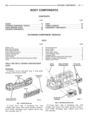
(5) Rotate bulb ring counterclockwise. Remove ring (12) Remove turn signal and side marker lamp
and bulb from lens (Fig. 3). sockets by twisting sockets clockwise.
(13) Remove lens.
Fig. 3 Headlamp Bulb Removal
(6) Open hood. Fig. 5 Turn Signal Lens
(7) Remove side marker lamp upper screw located
below radiator side closure panel (Fig. 4). (14) Repeat procedure for other side of front end.
(8) Remove lower screw located above park/turn (15) Remove license plate bracket if equipped, from
signal lamp. bumper fascia/crossmember.
(9) Pull out lamp. (16) Remove 6 retainers at front fascia (Fig. 6).
(10) Twist lamp socket clockwise. Disconnect lamp (17) Remove 3 plastic rivets at each front wheel
socket from lamp. well (Fig. 7).
(18) Slide fascia off retainer pegs at side of lower
crossmember.
(19) Remove fascia from lower crossmember (Fig.
6).
Fig. 6 Lower Fascia Removal
Fig. 4 Side Marker Lamp Removal
3. ZJ BODY COMPONENTS 23 - 3
Fig. 7 Wheel Well Retainers Fig. 9 GOR Air Seals
(20) Remove 8 bolts that attach grille opening re-
inforcement (GOR) to the upper and lower crossmem-
ber (Fig. 8).
Fig. 8 Grille Opening Reinforcement
(21) Remove grille opening reinforcement. Fig. 10 Underhood Lamp
(22) If necessary, remove air seals located at head-
lamp wiring inlets (Fig. 9). (4) Remove nuts that attach hinges to hood. Re-
move hood from vehicle with aid of a helper.
INSTALLATION
For installation, reverse removal procedure. INSTALLATION
(1) Position hood on shims and hinges. Finger-
RADIATOR SUPPORT CROSSMEMBER tighten hinge nuts (Fig. 11).
Refer to Group 7, Cooling Systems for service infor- (2) Align hinges and shims (Fig. 11) with installa-
mation. tion reference marks. Tighten hinge nuts to 23 N⅐m
(17 ft-lbs) torque.
HOOD (3) Test latch release cable and latches for proper
operation.
REMOVAL (4) Connect underhood lamp wire harness connec-
(1) Raise hood. tor.
(2) Disconnect underhood lamp wire harness con- (5) Inspect hood for proper alignment and adjust
nector (Fig. 10), if equipped. as necessary.
(3) Mark location of the hood hinges and hinge
shims (Fig. 11) for installation alignment.
4. 23 - 4 BODY COMPONENTS ZJ
Fig. 11 Hood Hinge Fig. 13 Hood Latch
HOOD ADJUSTMENT (4) Align latch striker (Fig. 14) so that striker en-
The hood attaching holes are enlarged to aid front, ters the latch squarely and without binding.
back and side-to-side adjustment.
(1) If hood is low in relation to cowl panel, insert
shims between hinge and hood.
(2) Adjust hood bumper (Fig. 12) in or out to ad-
just hood-to-fender height alignment.
Fig. 14 Hood Striker and Release Cable
HOOD HINGES
REMOVAL
(1) Remove hood from vehicle.
Fig. 12 Hood Bumper (2) Remove hinge retaining nuts from studs (Fig.
(3) Adjust the hood latch (Fig. 13) as necessary. 11).
Tighten the nuts to 11 N⅐m (8 ft-lbs) torque after ad- (3) Remove hinge from inner cowl side panel.
justment.
5. ZJ BODY COMPONENTS 23 - 5
INSTALLATION
(1) Position hinge over studs (Fig. 11).
(2) Install hinge retaining nuts on studs. Tighten
retaining nuts to 23 N⅐m (17 ft-lbs) torque.
(3) Install hood.
(4) Adjust hood as necessary. If necessary, refer to
adjustment procedure.
HOOD LATCH
REMOVAL
(1) Remove nuts that attach latch to radiator
crossmember support (Fig. 14).
(2) Disconnect latch from the hood release cable.
Remove latch.
INSTALLATION
(1) Connect latch to latch release cable. Position it
on radiator crossmember support (Fig. 14).
(2) Install nuts. Tighten nuts to 11 N⅐m (8 ft-lbs)
torque.
(3) Test operation of latch release cable and latch.
Fig. 15 Hood Release Cable
HOOD LATCH STRIKER (7) Test release cable for proper operation.
REMOVAL SAFETY LATCH STRIKER
(1) Remove 2 striker retaining bolts.
(2) Remove striker from hood (Fig. 14). REMOVAL
(1) Remove latch striker screw from hood (Fig. 14).
INSTALLATION (2) Remove striker from hood (Fig. 14).
(1) Position striker on hood.
(2) Install bolts (Fig. 14). Tighten bolts to 11 N⅐m INSTALLATION
(8 ft-lbs) torque. (1) Position striker on hood. Install screw (Fig. 14).
(3) Test striker/hood alignment by opening and clos- (2) Test safety latch operation.
ing hood several times. Adjust striker, if necessary.
COWL GRILLE AND SCREEN
LATCH RELEASE CABLE
REMOVAL
REMOVAL (1) Use a wax pencil to mark position of wiper
(1) Disconnect cable from hood latch (Fig. 13). arms (Fig. 16).
(2) Disconnect cable from retaining clips (Fig. 14).
(3) Remove left cowl side (kick) trim panel.
(4) Remove cable bracket attaching screws from
cowl side panel (Fig. 15).
(5) Pull cable through dash panel and remove it
from under instrument panel.
INSTALLATION
(1) Insert replacement cable end through hole in
dash panel (Fig. 15) into engine compartment.
(2) Pull cable forward and seat grommet in dash
panel (Fig. 15).
(3) Position cable bracket on cowl side panel and
install screws (Fig. 15). Tighten screws to 11 N⅐m (8
ft-lbs) torque.
(4) Install left cowl side trim panel.
(5) Route cable into retaining clips.
(6) Attach cable to hood latch (Fig. 13). Fig. 16 Wiper Locations On Windshield
6. 23 - 6 BODY COMPONENTS ZJ
(2) Remove windshield wiper arms from pivots INSTALLATION
(Fig. 16). (1) Position cowl grille on cowl. Install windshield
washer tubes on nozzles.
(2) Install cowl grille retaining screws.
(3) Install windshield wiper arms on pivots with
wipers aligned with wax pencil.
BATTERY TRAY
REMOVAL
(1) Remove 2 bolts and holddown bracket from bat-
tery tray (Fig. 19).
Fig. 17 Cowl Grille Components
(3) Remove 6 screws that attach grille to cowl (Fig.
17).
(4) Remove windshield washer tubes from nozzles
(Fig. 18).
Fig. 19 Battery Tray
(2) Remove battery thermo-guard from battery.
(3) Remove battery from tray.
(4) Remove screws that attach battery tray to in-
ner fender panel.
(5) Remove battery tray. Disconnect vacuum reser-
voir hoses.
(6) If necessary, remove screws that attach reser-
voir to bottom of battery tray.
INSTALLATION
Fig. 18 Washer Fluid Tubes (1) If removed, install vacuum reservoir and
screws to bottom of tray.
(5) Remove cowl grille and screen from cowl (Fig.
(2) Position battery tray on inner fender panel.
17).
Connect vacuum lines to reservoir.
7. ZJ BODY COMPONENTS 23 - 7
(3) Attach battery tray to inner fender panel with
screws (Fig. 19). Tighten screws to 10 N⅐m (7 ft-lbs)
torque.
(4) Install battery in tray.
(5) Position upper holddown bracket over battery.
(6) Install holddown bracket and holddown bolts.
Tighten the bolts to 10 N⅐m (7 ft-lbs) torque.
FRONT FENDER
REMOVAL
(1) Remove headlamp, side marker and turn signal
lamp. Refer to Group 8L, Lamps for service informa-
tion.
(2) Remove front bumper fascia. Refer to Group 13,
Frame and Bumpers for service information.
(3) Remove front wheel.
(4) Remove fasteners attaching inner front fender
liner to fender and inner fender (Fig. 20).
Fig. 21 Radio Antenna
Fig. 20 Inner Fender Liner
(5) Remove inner fender liner.
(6) Right fender only:
• If equipped, remove radio antenna mast, nut, pad
and base from fender (Fig. 21 and 22).
(7) From inside wheel well, remove bolts at rear of
fender reinforcements (Fig. 23).
(8) Remove bolts at front fender bracket (Fig. 24).
(9) Remove bolts at lower rear of fender at A-pillar
(Fig. 24).
(10) Remove upper mounting bolts at top of fender Fig. 22 Power Antenna
(Fig. 24). (6) Install front bumper fascia. If necessary refer
(11) Remove fender from inner fender. to Group 13, Frame and Bumpers for installation in-
structions.
INSTALLATION (7) Install front headlamp, side marker and turn
(1) Position fender on inner fender panel (Fig. 24). signal lamp. If necessary refer to Group 8L, Lamps
(2) Install all of fender attaching screws finger- for service information.
tight.
(3) Align fender with adjacent body panels.
Tighten fender bolts to 9 N⅐m (80 in-lbs) torque.
(4) Install inner fender liner.
(5) Install front wheel.
8. 23 - 8 BODY COMPONENTS ZJ
Fig. 23 Inner Fender Mounting Fig. 25 Body Side Cladding
(4) Install acorn nut onto retainer.
REMOVAL/FENDER-QUARTER PANEL
(1) Remove 3 screws at wheel opening.
(2) Using a trim stick, Gently pry upward from
bottom of cladding.
(3) Unsnap cladding from retainers.
INSTALLATION/FENDER-QUARTER PANEL
(1) Install molding over top of retainer clips.
(2) Snap molding down over retaining clips.
(3) Install screws into wheel opening.
BODY STRIPES/DECALS
GENERAL INFORMATION
Fig. 24 Fender Mounting Body stripes are durable, weather-resistant tape
stripes with pressure-sensitive backing. The tape
BODY SIDE CLADDING
stripe is protected by a carrier until installed on a
REMOVAL/FRONT DOOR body panel. Carrier also is an installation alignment
(1) Using a trim stick, gently lift up from bottom of aid (Fig. 1).
cladding. Unsnap molding from retaining clips (Fig.
25).
(2) Lift upward and remove molding.
INSTALLATION/FRONT DOOR
(1) Install molding over top of retaining clips.
(2) Align molding to door edges.
(3) Snap molding down over retaining clips.
REMOVAL/REAR DOOR
(1) Open rear door.
(2) Remove acorn nut at rear dogleg (Fig. 25).
(3) Using a trim stick, gently lift up from bottom of
cladding. Unsnap molding from retaining clips.
INSTALLATION/REAR DOOR
(1) Install molding retainer into hole at dogleg. Fig. 1 Tape Stripes
(2) Install molding over top of retaining clips.
(3) Snap molding down over top of retaining clips.
9. ZJ BODY COMPONENTS 23 - 9
REMOVAL (12) Apply heat to tape stripe to evaporate residual
(1) Remove exterior trim as necessary to clear cap- moisture from edges of tape stripe. This will also al-
tured edges of tape stripe being removed low tape stripe to be stretched into concave surfaces.
(2) Remove tape stripe using a suitable heat gun (13) Edge turn tape stripe around doors or fenders.
or lamp. (14) Install exterior trim if necessary. Small air or
This will soften adhesive backing. water bubbles under tape stripe can be pierced with
(3) Clean adhesive residue from body finish using a pin and smoothed out.
a suitable adhesive remover.
QUARTER WINDOW APPLIQUE/AIR EXHAUSTER
INSTALLATION
REMOVAL
INSTALLATION EQUIPMENT (1) Using a trim stick, carefully pry applique from
• Bucket filled with a mild dish soap solution. panel (Fig. 2).
• Lint free applicator cloth or sponge.
• Body putty applicator squeegee.
• Heat gun or sun lamp.
• Razor knife.
The painted surface of the body panel to be covered
by a tape stripe must be smooth and completely
cured before stripe can be applied. If painted surface
is not smooth, wet sand with 600 grit wet/dry sand
paper until surface is smooth.
Ripples and feather edges will read through stripe
if surface is not properly prepared.
(1) With backing still in place, position stripe
across panel to receive the stripe. Apply masking at
top of stripe to hold it in position.
(2) Mark outside edge of panel on stripe with
grease pencil. Fig. 2 Quarter Window Applique & Air Exhauster
(3) Trim stripe to within 17 mm (0.750 in.) of out-
line marks. (2) Carefully pry air exhauster from upper quarter
panel using a flat blade screwdriver.
(4) Spread stripe across a smooth flat work sur-
face, stripe side down. INSTALLATION
(5) Peel paper backing away from stripe exposing (1) Reseal air exhauster using foam tape.
adhesive backing of stripe. (2) Install air exhauster on panel.
(6) Apply soap solution liberally to adhesive back- (3) Position applique on panel with retainers
ing of stripe. aligned (Fig. 2). Press applique firmly in place.
(7) Apply soap solution to body panel surface.
(8) Place stripe into position on body panel (Fig. EXTERIOR NAMEPLATES
29). Smooth out wrinkles by pulling lightly on edges
of tape stripe until it lays flat on panel surface. SERVICE INFORMATION
(9) Push air pockets from under tape stripe to pe- All of the vehicle exterior nameplates (Fig. 3), are
rimeter of panel from center of the tape stripe out. attached to the vehicle panels with adhesive.
(10) Remove air bubbles from under tape stripe us-
REMOVAL/INSTALLATION
ing a body putty squeegee.
(1) Carefully pry nameplate (Fig. 3) from body
CAUTION: Do nut cut into painted surface of body panel.
when trimming tape stripe to size. (2) Clean panel surface.
(3) Position replacement nameplate on panel and
(11) Trim tape stripe to size using a razor knife. push inward to seat it.
Leave at least 13 mm (0.5 in.) for edges of doors and
openings. EXTERNAL MIRRORS
CAUTION: Do not overheat tape stripe when per- REMOVAL
(1) Remove door trim panel.
forming step 12.
(2) Remove mirror inside trim cover attaching
screw.
10. 23 - 10 BODY COMPONENTS ZJ
(4) Install inside trim cover.
(5) Install inside trim cover attaching screw and
tighten it securely.
(6) Install door trim panel.
LUGGAGE RACK
REMOVAL
(1) Remove slide rail screws (Fig. 5).
Fig. 3 Exterior Nameplates
(3) For power mirrors, remove inside trim cover.
(4) For remote control mirrors, loosen toggle con-
trol setscrew.
(5) For remote control mirrors, remove inside trim
cover.
(6) Remove mirror retaining nuts (Fig. 4).
(7) Remove mirror from door. Refer to Group 8,
Electrical for additional information involving power
mirrors.
Fig. 5 Luggage Rack
(2) Remove luggage rack from vehicle roof.
The skid strips are attached to roof panel
with adhesive.
(3) Loosen each skid strip (Fig. 5) with a heat gun.
(4) Lift one edge of each skid strip with a putty
knife and peel it from roof panel. Apply additional
heat to any location where a skid strip remains.
(5) Remove original adhesive from roof panel with
an all-purpose adhesive removal solution.
INSTALLATION
(1) Install 3M 06379 double-sided tape on skid
strips.
(2) Align each skid strip on roof panel.
(3) Verify that each skid strip is properly aligned.
(4) Press each skid strip onto roof panel with a
Fig. 4 Exterior Mirror roller.
INSTALLATION Apply 3M Drip-Chek Sealant (or an equiva-
(1) Position mirror on door. Verify that the O-ring lent product) to underside of side rail screw
seal and gasket are properly positioned. heads.
(2) Install mirror retaining nuts. (5) Position luggage rack on roof.
(3) For remote mirrors, position inside trim cover (6) Install and tighten slide rail screws to 3 N⅐m
over toggle control. Tighten setscrew. (28 in-lbs) torque.
11. ZJ POWER SUNROOF 23 - 11
POWER SUNROOF
INDEX
page page
Adjustment Bracket . . . . . . . . . . . . . . . . . . . . . . . . 12 Glass Vertical Height Adjustment . . . . . . . . . . . . . . 11
Drain Channel . . . . . . . . . . . . . . . . . . . . . . . . . . . . 13 Guide Assembly . . . . . . . . . . . . . . . . . . . . . . . . . . 14
Drive Cable Locators . . . . . . . . . . . . . . . . . . . . . . . 13 Motor and Drive Gears . . . . . . . . . . . . . . . . . . . . . 13
Drive Cables . . . . . . . . . . . . . . . . . . . . . . . . . . . . . 13 Sunshade . . . . . . . . . . . . . . . . . . . . . . . . . . . . . . . 14
General Information . . . . . . . . . . . . . . . . . . . . . . . . 11 Wind Deflector . . . . . . . . . . . . . . . . . . . . . . . . . . . 11
Glass Panel . . . . . . . . . . . . . . . . . . . . . . . . . . . . . 11
GENERAL INFORMATION GLASS VERTICAL HEIGHT ADJUSTMENT
All sunroofs are equipped with drain tubes (Fig. 1
and 2). The drain tubes must be kept open to prevent GLASS VERTICAL ADJUSTMENT
water from entering passenger compartment. (1) Open glass to vent position.
(2) Slide upper half of mechanism covers rearward
until clips disengage and separate covers from vehi-
cle (Fig. 3).
(3) Close glass panel, separately loosen adjusting
bolts (Fig. 3—View A) and individually adjust the
corners of the glass.
(4) Adjust front of glass panel to 1.0 mm (0.040 in.)
below top surface of roof panel.
(5) Adjust rear of glass to 1.0 mm (0.040 in.) above
top surface of roof panel.
(6) Secure adjustment bolts and install covers.
WIND DEFLECTOR
REMOVAL
(1) Open sun roof glass panel.
(2) Remove screws holding wind deflector to sun
roof unit side rail (Fig. 4).
(3) Separate wind deflector from vehicle.
INSTALLATION
Fig. 1 Drain Tubes Reverse preceding operation.
LUBRICATION
GLASS PANEL
(1) Lubricate cables with Lubriplate or equivalent
when cables are replaced. REMOVAL
(2) Periodically clean dirt from guide rail covers. (1) Position glass to vent position.
(2) Remove wind deflector mechanism covers (Fig.
DRAIN TUBES 3)
• Inspect drain holes, located in trough around sun- (3) Position sunshade full rearward.
roof opening to verify they are clear. Inspection (4) Loosen nuts holding glass panel to side adjust-
should be performed once a year or when problems ment brackets (Fig. 3—View B).
are suspected. If drain hose or tubes are plugged, use (5) Slide glass panel rearward 12mm (0.5in.) and
compressed air or blunt flexible wire to clear them. If separate glass from sunroof unit.
tubes cannot be cleared, they must be repaired.
• The lower ends of rear drain tubes are located in INSTALLATION
rear quarter panel drop wells. To clear rear drain (1) Position glass panel in opening with logo rear-
tubes, remove the plug/adapter and use compressed ward and slide panel forward 12 mm (0.5in.).
air or a blunt flexible wire from the lower ends of (2) Verify that attaching nuts are below top surface
tubes. of glass adjustment brackets.
12. 23 - 12 POWER SUNROOF ZJ
Fig. 2 Drain Tube Locations
Fig. 4 Deflector Assembly
(6) Close glass and check alignment.
(7) Locate glass to vent position.
(8) Install mechanism covers.
ADJUSTMENT BRACKET
Fig. 3 Glass Adjustment
(3) Close sunroof to center glass panel in roof open- REMOVAL AND INSTALLATION
ing. (1) Remove wind deflector, mechanism covers and
(4) Tighten center screws to hold adjustment. glass panel.
(5) Open glass to vent position and tighten nuts to
8 N⅐m (70.8 in. lbs.).
13. ZJ POWER SUNROOF 23 - 13
(2) Move glass carriage to vent position and re-
move rearward adjustment bolt from adjustment
bracket.
(3) Lift rear of adjustment bracket to highest ver-
tical position and disengage front of bracket from
unit (Fig. 5).
Fig. 6 Removing Cable Drive Locator
MOTOR AND DRIVE GEARS
REMOVAL
(1) Open sunroof to vent position.
(2) Remove headlining.
(3) Remove bolts holding sunroof motor to motor
bracket.
(4) Disconnect wire connector.
(5) Separate motor and drive gear from drive ca-
bles (Fig. 7).
Fig. 5 Adjustment Bracket Removal/Installation
(4) For installation reverse the preceding opera-
tion. Adjust glass as necessary.
DRAIN CHANNEL
REMOVAL AND INSTALLATION
(1) Locate glass to vent position.
(2) Remove mechanism covers and glass panel.
(3) Remove screws holding drain channel to sup-
port frame. Fig. 7 Sunroof Motor And Drive Gear
(4) For installation reverse preceding operation.
INSTALLATION
DRIVE CABLE LOCATORS (1) Verify that sunroof is in vent position. Push
mechanism forward on both sides to align drive ca-
REMOVAL AND INSTALLATION bles.
(1) Position glass 19 mm (0.75 in.) until rearward (2) Engage drive gears onto drive cables.
cable locator is visible. (3) Install motor and drive gear screws and tighten
(2) Remove screws holding drive cable locator to to 5 N⅐m (44in-lbs.).
unit. (4) Install headlining.
(3) Remove travel limiting micro switch grommet
and disconnect wire connector. DRIVE CABLES
(4) Insert a small screwdriver under rear edge of
locator and pry locator from track (Fig. 6). REMOVAL
(5) For installation reverse preceding operation. (1) Open sunroof to vent position.
The small out-board lip underneath cable locator (2) Remove headlining, wind deflector, mechanism
slips under bottom slot on guide track. After locator covers, glass panel, side glass adjustment brackets,
is seated install screws. motor and drive cable locators.
14. 23 - 14 POWER SUNROOF ZJ
(3) Lift cable out of cable retainer and pull for-
ward. Separate cable from assembly (Fig. 8).
Fig. 9 Sunshade
(4) Remove screws holding front and center guide
Fig. 8 Drive Cables track to unit.
(5) Pull cable out of groove for cable end.
INSTALLATION
(6) Pull guide outward to release from housing.
Verify sunroof is in vent position. Push mechanism
Separate rear end of guide from clips. Slide guide out
forward on both sides to align drive cables. Reverse of unit (Fig. 10).
the preceding operation.
SUNSHADE
REMOVAL AND INSTALLATION
(1) Remove wind deflector, mechanism covers and
glass panel.
(2) Position system to full rearward position.
(3) Slide sunshade panel full forward and release
the front tabs from track assembly.
(4) Pull front and rear retaining clips inboard and
lift sunshade out (Fig. 9).
Fig. 10 Guide Assembly
(5) For installation reverse preceding operation.
INSTALLATION
GUIDE ASSEMBLY (1) Install guide cable into rear of guide assembly.
(2) Install guide assembly at an angle so the rear
REMOVAL portion slips under finger clips at rear of module
(1) Remove wind deflector, mechanism covers, housing.
glass panel, drain channel, sunshade and drive cable (3) Place cable in groove of cable holder.
locator as necessary. (4) Install screws in track assembly.
(2) Move glass carriage to vent position. (5) Install locators.
(3) Remove front slide from guide assembly. (6) Reverse removal operation.
16. 23 - 16 DOORS ZJ
Fig. 4 Right Power Door Switches
Fig. 5 Door Hinges and Bolts
INSTALLATION
fer to adjustment procedure. Tighten hinge bolts to
(1) Connect rods to inside handle assembly. Install
35 N⅐m (26 ft-lbs) torque.
handle assembly (Fig. 2). Tighten screws to 2 N⅐m
(10) Adjust latch striker as necessary.
(16 in-lbs) torque.
(11) If applicable, route and connect harness con-
(2) Apply adhesive/sealant to edges of door water-
nectors to door and vehicle body wire harness connec-
dam.
tors.
(3) Position waterdam on door inner panel. Press it
(12) Install door waterdam (if removed), trim
inward to attach it to inner panel.
panel, armrest and window glass regulator handle. If
(4) If removed, install power door switches (Fig. 3
necessary, refer to trim panel installation procedure.
and 4).
(5) Position trim panel on door inner panel. For ve- DOOR ALIGNMENT ADJUSTMENT—MINOR
hicles equipped with power door locks/windows, con-
Minor adjustment for alignment of the door is
nect wire harness connectors. Press nylon retainers
made by moving the latch striker.
inward to attach it to inner panel (Fig. 2).
(6) Install armrest screw. Install demister slot IN AND OUT
screw. Install mirror bezel screw (Fig. 2). Tighten (1) Loosen the latch striker.
screws to 4 N⅐m (34 in-lbs) torque. (2) Tap the latch striker inward if the door charac-
(7) Install window crank handle. ter line is outboard of the body character line or tap
the latch striker outward if the door character line is
DOOR REMOVAL/INSTALLATION inboard of the body character line.
(1) For vehicles equipped with power windows and (3) Inspect alignment. If correct, tighten striker
locks, remove door trim panel. Disconnect power win- with 28 N⅐m (21 ft. lbs.) torque.
dow regulator, power door lock motor and all other
wire harness connectors. Slide wire harness out of UP AND DOWN
boot and door. (1) Loosen the latch striker.
(2) Mark an outline around door hinges for instal- (2) Tap the latch striker downward if the door
lation alignment reference. character line is higher than the body character line
(3) Remove door hinge, retaining bolts, plates and or tap the latch striker upward if the door character
shims (Fig. 5). Remove door from vehicle. line is lower than the body character line.
(4) Identify and retain door hinge plates and shims (3) Inspect alignment. If correct, tighten striker
for correct installation (Fig. 5). with 28 N⅐m (21 ft. lbs.) torque.
(5) If a replacement front door is being installed,
coat door interior with anti-corrosion wax. Also, seal FRONT DOOR WINDOW REGULATOR
door hem flange with sealant.
(6) Before installing a replacement door, transfer REMOVAL
original hardware. If necessary, refer to applicable (1) Remove door trim panel and waterdam. If nec-
procedures. essary, refer to removal procedure.
(7) Position door in body opening. (2) Position window glass to access window track
(8) Align door hinges, plates and shims with bolt nuts (Fig. 6).
holes. Install (but do not tighten) hinge bolts (Fig. 5). (3) Loosen 2 window track nuts and slide track off
(9) Adjust door to reference marks. If necessary, re- of the window (Fig. 6).
17. ZJ DOORS 23 - 17
Fig. 6 Front Door Window Track
(4) Remove 4 window regulator retaining screws
(Fig. 7).
Fig. 8 Rear Door Window Track
(3) Loosen 2 window track nuts and slide track off
of window (Fig. 8).
(4) Remove 4 window regulator retaining screws
(Fig. 9).
Fig. 7 Front Door Window Regulator
(5) Lift window upward and separate it from regu-
lator. Support window.
(6) Remove window regulator from door.
Reverse removal procedure for installation.
FRONT DOOR WINDOW Fig. 9 Rear Door Window Regulator
(5) Lift window upward and separate it from regu-
REMOVAL lator. Support window.
(1) Remove door trim panel and waterdam. If nec- (6) Remove window regulator from door.
essary, refer to removal procedure. Reverse removal procedure for installation.
(2) Remove beltline molding and weatherstrip
seals. REAR DOOR WINDOW
(3) Remove window track retaining nuts (Fig. 6). If
necessary, refer to removal procedure. REMOVAL
(4) Lift window glass upward and out of door. (1) Lower window glass.
For installation, reverse removal procedure. (2) Remove trim panel and waterdam from door in-
ner panel. If necessary, refer to removal procedure.
REAR DOOR WINDOW REGULATOR (3) Pry window beltline molding from flange. Re-
move molding from door.
REMOVAL (4) Remove window weatherstrip seals from door.
(1) Remove door trim panel and waterdam. If nec- (5) Remove window track nuts and slide track off
essary, refer to removal procedure. of window (Fig. 8).
(2) Position window glass to access window track (6) Remove division bar upper attaching screw and
nuts (Fig. 8). belt line screw (Fig. 10).
18. 23 - 18 DOORS ZJ
(3) If equipped, disconnect security alarm switch
connector from lock cylinder (Fig. 12).
Fig. 10 Stationary Glass Channel
(7) Tilt stationary glass channel assembly forward
and remove it from door.
(8) Remove window glass from door.
INSTALLATION
(1) Install window glass in door.
(2) Tighten glass track nuts to 6 N⅐m (53 in-lbs)
torque.
Fig. 12 Security Alarm Switch
(3) Install stationary glass channel in door.
(4) Install stationary glass channel screws (Fig. (4) Remove key lock cylinder retainer clip. Remove
10). Tighten screw to 6 N⅐m (5 ft-lbs) torque. lock cylinder, gasket and clip from door (Fig. 11).
(5) Install window glass channel and belt weather- (5) If applicable, remove door latch lock cylinder
strip seals. rod from original lock cylinder. Connect it to replace-
(6) Install window beltline molding. ment lock cylinder.
(7) Install door waterdam and trim panel. If neces- For installation, reverse removal procedure.
sary, refer to installation procedure.
DOOR LATCH ADJUSTMENT
DOOR KEY LOCK CYLINDER (1) Locate access hole (Fig. 13).
REMOVAL
(1) Remove door trim panel and waterdam. If nec-
essary. refer to removal procedure.
(2) Disconnect door latch lock cylinder rod at door
latch (Fig. 11).
Fig. 13 Door Latch Adjustment
(2) Insert a 5/32-inch hex-wrench through hole and
into adjustment screw. Loosen screw.
(3) Operate outside handle button several times to
release any restriction because of mis-alignment.
Fig. 11 Key Lock Cylinder & Door Latch
19. ZJ DOORS 23 - 19
(4) Tighten adjustment screw to 3 N⅐m (30 in-lbs) (4) Disconnect wire connector, if equipped.
torque. (5) Remove door latch from door.
(5) Test handle button and lock cylinder for proper For installation, reverse removal procedure.
operation.
DOOR INSIDE LATCH RELEASE AND LOCK RODS
OUTSIDE DOOR HANDLE
REMOVAL
REMOVAL (1) Remove door trim panel and waterdam. If nec-
(1) Remove door trim panel and waterdam. If nec- essary, refer to removal procedure.
essary, refer to removal/installation procedure. (2) Remove door inside latch release handle screws
(2) Remove access hole cover and door handle re- (Fig. 16 and 17).
taining nuts.
(3) Disconnect handle latch rod from latch (Fig.
11).
For installation, reverse removal procedure.
DOOR LATCH
REMOVAL
(1) Remove door trim panel and waterdam. If nec-
essary, refer to removal procedure.
(2) Remove door latch retaining screws (Fig. 14).
Fig. 16 Front Door Inside Latch Release Handle
Fig. 14 Door Latch Retaining Screws
(3) Disconnect all rods from door latch (Fig. 15).
Fig. 15 Door Latch Fig. 17 Rear Door Inside Latch Release Handle
20. 23 - 20 DOORS ZJ
(3) Move door release handle outward. Disconnect
handle latch and lock rods.
(4) Remove door inside release handle from door.
For installation, reverse removal procedure.
DOOR WINDOW EXTERIOR MOLDINGS
REMOVAL
(1) Lower window glass completely.
(2) Carefully pull molding from door panel flange
and/or retaining clips.
INSTALLATION
(1) When installing window moldings, start at for-
ward end of molding.
(2) Force molding onto door flange. Continue rear-
ward until it is seated on flange. Fig. 1 Liftgate Trim Panel
(3) Mate rear molding with upper molding. Force
molding edge inward.
(4) Continue pressing downward to complete in-
stallation.
DOOR WINDOW GLASS AND DOOR OPENING
SEALS
The window glass seals can be removed by hand.
The door opening seal is attached to edge of door
opening in body. The front door secondary seal is at-
tached to A-pillar.
WINDOW GLASS SEAL INSTALLATION
When installing front or rear door window glass
weatherstrip seals, open window completely.
(1) To install a front door window channel weath- Fig. 2 Liftgate Retainer Location
erstrip seal, start at upper, rear corner.
(2) To install a rear door window glass channel (3) Remove trim panel from liftgate.
weatherstrip seal, start at upper, front corner.
INSTALLATION
(3) Install seal evenly until it is fully seated in
(1) Position trim panel on liftgate.
channel.
(4) Position belt weatherstrip seals at window (2) Align trim panel retainers with holes in liftgate
edge. Force them downward until seated on flange. inner panel. Force trim panel inward to seat retain-
ers in holes (Fig. 2).
DOOR OPENING WEATHERSTRIP SEAL (3) Install screws to attach panel to liftgate (Fig.
INSTALLATION 1). Tighten screws securely.
(1) When installing a door opening weatherstrip
seal, start at rear of front seal and front of rear seal LIFTGATE
using paint dots as location points.
(2) Use adhesive along with push-studs to aid in REMOVAL
retaining a weatherstrip seal.
(3) Move upward and around edge of door opening. WARNING: DO NOT DISCONNECT THE SUPPORT
Seat seal on flange. ROD CYLINDERS WITH THE LIFTGATE CLOSED.
THE SUPPORT ROD PISTONS ARE OPERATED BY
LIFTGATE TRIM PANEL HIGH PRESSURE GAS. THIS PRESSURE COULD
CAUSE DAMAGE AND/OR PERSONAL INJURY IF
REMOVAL THEY ARE REMOVED WHILE THE PISTONS ARE
(1) Remove the CHMSL access panel. Remove the COMPRESSED.
screws that attach liftgate panel to liftgate (Fig. 1).
(2) Use a trim panel removal tool to detach panel (1) Open liftgate. Support liftgate for ease of re-
retainers from liftgate (Fig. 2). pair.
21. ZJ DOORS 23 - 21
(2) Remove liftgate trim panel (Fig. 1). If neces- (1) Remove liftgate opening (headliner) upper trim
sary, refer to removal procedure. molding (Fig. 5). Disconnect wiring harness to cargo
(3) Remove retainer clips that secure support rod lamp.
cylinders to ball studs (Fig. 3).
Fig. 3 Liftgate Prop Rod
(4) Remove support rod cylinders from ball studs
(Fig. 23).
(5) Remove upper support rod retaining screws
(Fig. 23). Remove support rods. Fig. 5 Liftgate Upper Trim Molding
(6) Disconnect wire harnesses and washer hose
from liftgate. (2) Remove hinge screws at roof panel (Fig. 4).
(7) Remove hinge screws at liftgate (Fig. 4). (3) Remove hinge screws at liftgate (Fig. 4).
(8) Remove liftgate from vehicle. (4) Remove hinge from liftgate (Fig. 4).
For installation, reverse removal procedure.
INSTALLATION
Tighten hinge screws to 28 N⅐m (21 ft-lbs) torque.
(1) Position hinge on liftgate and roof panel (Fig.
4). (Use 3M™ Fast and Firm or equivalent on the
hinge to body mating surface as a sealant).
(2) Install and tighten hinge screws at roof panel
to 28 N⅐m (21 ft-lbs) torque.
(3) Install hinge screws at liftgate. Tighten screws
to 28 N⅐m (21 ft-lbs) torque.
(4) Install liftgate opening (headliner) upper trim
molding (Fig. 5).
LIFTGATE LATCH/LOCK COMPONENTS
REMOVAL
(1) Raise liftgate. Remove liftgate trim panel. If
necessary refer to service procedure.
(2) Remove latch screws (Fig. 6).
(3) Disconnect rod from latch (Fig. 6).
Fig. 4 Liftgate Components
(4) Disconnect power lock connector, if equipped
LIFTGATE HINGE (Fig. 7).
(5) Remove latch from liftgate (Fig. 6 and 7).
REMOVAL (6) Remove lock cylinder retainer clip (Fig. 6).
It is not necessary to remove liftgate to replace one (7) Remove key lock cylinder.
or both hinges. The hinges can be replaced one at a (8) Remove nuts retaining the liftgate handle. Re-
time. move the handle (Fig. 6 and 7).
22. 23 - 22 DOORS ZJ
LIFTGATE ADJUSTMENT
The position of liftgate can be adjusted upward or
downward by use of slots in the hinge. An inward or
outward adjustment is achieved by use of slots in the
body. If an inward or outward adjustment is needed,
use 3M™ Fast and Firm or equivalent on the hinge
to body mating surface as a sealant.
LIFTGATE OPENING WEATHERSTRIP SEAL
REMOVAL
(1) Pull seal away from flange around edge of lift-
gate opening. Remove it from vehicle.
(2) Clean seal flange as necessary.
INSTALLATION
Fig. 6 Liftgate Latch/Lock Component
(1) Position weatherstrip seal in opening with left
end of seal at opening centerline. Install seal in a
clockwise direction.
(2) Seat installed part of seal. Move from left bot-
tom end of seal to top left half of the seal.
(3) Center and butt seal ends together at center-
line.
LICENSE PLATE LAMP HOUSING
REMOVAL
(1) Remove liftgate trim panel
Fig. 7 Power Lock Handle (2) Remove lamp housing retaining screws from
liftgate (Fig. 9).
(9) Remove latch striker nuts from below scuff
plate. Access nuts from under bumper fascia/beam.
(Fig. 8)
Fig. 8 Liftgate Latch Striker
(10) Remove striker, shim and seal plate (Fig. 8).
For installation of components, reverse removal
procedure. Tighten striker nuts to 54 N⅐m (40 ft. lbs.) Fig. 9 License Plate Lamp Housing
and tighten latch screws to 7 N⅐m (5 ft. lbs.) torque. (3) Disconnect bulb socket from lamp housing.
(4) Disconnect Flip-Up glass switch connector, if
equipped.
(5) Remove housing from liftgate.
23. ZJ DOORS 23 - 23
INSTALLATION
(1) Position lamp housing at liftgate.
(2) Connect bulb socket to lamp housing.
(3) Connect Flip-Up glass switch connector, if
equipped.
(4) Install lamp housing retaining screws in lift-
gate. Tighten screws securely.
(5) Install liftgate trim panel.
LIFTGATE FLIP-UP GLASS
REMOVAL
WARNING: DO NOT DISCONNECT THE PROP ROD
CYLINDERS WITH THE LIFTGATE FLIP-UP GLASS
CLOSED. THE PROP ROD PISTONS ARE OPER-
ATED BY HIGH PRESSURE GAS. THIS PRESSURE Fig. 11 Prop Rod Removal
COULD CAUSE DAMAGE AND/OR PERSONAL IN-
JURY IF THEY ARE REMOVED WHILE THE PIS-
TONS ARE COMPRESSED.
(1) Open liftgate flip-up glass. Support glass for
ease of repair.
(2) Using a small flat blade or equivalent tool, gen-
tly pry open the locking caps on the end of the prop
rod. (Fig. 10).
Fig. 12 Hinge Removal
(2) Position hinges on to glass panel and finger
tighten screws.
(3) Install handle/striker. Tighten screws to 6 N⅐m
(60 in. lbs.).
INSTALLATION
(1) Position flip-up glass on liftgate.
(2) Install hinge nuts. Tighten nuts to 6 N⅐m (60
Fig. 10 Prop Rod Removal in. lbs.).
(3) Remove prop rod cylinders from ball studs (Fig. (3) Check alignment of glass panel. If panel is
11). aligned correctly, tighten hinge screw to 6 N⅐m (60 in.
(4) Remove hinge nuts from liftgate (Fig. 12). lbs.).
(5) Separate flip-up glass from vehicle. (4) Install prop rods onto ball studs (Fig. 11) and
compress locking caps to lock prop rods onto ball
DISASSEMBLY studs.
(1) Remove ball studs from glass panel.
LIFTGATE FLIP-UP GLASS LATCH/LOCK
(2) Remove hinge from glass panel.
(3) Remove handle/striker. COMPONENTS
ASSEMBLY REMOVAL
(1) Raise liftgate. Remove liftgate trim panel. If
(1) Install ball studs onto glass panel. Tighten
necessary refer to service procedure.
screws to 6 N⅐m (60 in. lbs.). (2) Remove latch nuts (Fig. 13).
24. 23 - 24 DOORS ZJ
(3) Squeeze switch locking tabs inward to release
switch from license plate lamp housing.
(4) Disconnect switch harness connector.
(5) Separate switch from housing (Fig. 15).
Fig. 13 Flip-Up Glass Latch/Lock Component
(3) Disconnect switch connector.
(4) Remove latch from liftgate.
INSTALLATION Fig. 15 Switch Removal
(1) Position latch on vehicle, 2.5 mm forward of seal.
INSTALLATION
(2) Connect switch connector.
(1) Position switch into license plate lamp housing
(3) Install latch nuts. Tighten to 11 N⅐m (100 in. lbs.).
and connect switch harness connector.
(4) Close flip-up glass panel and verify proper op- (2) Snap switch into place.
eration. (3) Install license plate lamp housing.
(5) Install liftgate trim panel. (4) Install liftgate trim panel.
FLIP-UP GLASS SWITCH LIFTGATE FLIP-UP GLASS WEATHERSTRIP SEAL
REMOVAL REMOVAL
(1) Remove liftgate trim panel. (1) Slowly pull seal away from flange around edge
(2) Remove license plate lamp housing nuts from of glass opening. Remove it from vehicle.
liftgate (Fig. 14). (2) Clean seal flange as necessary.
INSTALLATION
(1) Position weatherstrip seal with paint dots
aligned with window opening corners.
(2) Seat seal firmly around entire liftgate (Fig. 16).
(3) Butt seal ends together and smooth out any re-
maining length.
Fig. 14 License Plate Lamp Housing Fig. 16 Liftgate Seal
25. ZJ FIXED WINDOW GLASS 23 - 25
FIXED WINDOW GLASS
INDEX
page page
Fixed Glass Water Leak Detection and Repair . . . . 27 Windshield Replacement . . . . . . . . . . . . . . . . . . . . 25
Safety Precautions and Warnings . . . . . . . . . . . . . 25
SAFETY PRECAUTIONS AND WARNINGS
WARNING: DO NOT USE URETHANE ADHESIVE OR
PRIMER IN CLOSED WORK AREA, PERSONAL IN-
JURY CAN RESULT. PROTECT SKIN FROM COMING
IN CONTACT WITH URETHANE, PERSONAL INJURY
CAN RESULT. WEAR EYE AND HAND PROTECTION
WHEN WORKING WITH GLASS, PERSONAL INJURY
CAN RESULT.
CAUTION: Protect all painted or trimmed surfaces
from coming in contact with urethane or primers,
damage will result. Do not damage painted surfaces
when removing moldings or cutting urethane
around windshield.
Fig. 1 Rear Quarter Glass
WARNING: DO NOT OPERATE VEHICLE FOR AT
LEAST 24 HOURS AFTER WINDSHIELD INSTALLA-
TION. WINDSHIELD MAY NOT PERFORM PROP-
ERLY IN THE EVENT OF A COLLISION IF
URETHANE ADHESIVE IS NOT SUFFICIENTLY
CURED. REFER TO MANUFACTURER OF URE-
THANE BEING USED FOR CURING TIME SPECIFI-
CATIONS. WHEN INSTALLING GLASS, DO NOT USE
URETHANE ADHESIVE AFTER DATE ON PRODUCT
HAS EXPIRED. SAFETY AND QUALITY OF REPAIR
WOULD BE QUESTIONABLE.
It is difficult to salvage a windshield during the re-
moval operation. The windshield is part of the struc-
tural support for the roof. The urethane bonding
used to secure windshield to fence is difficult to cut
or clean from any surface. If moldings are set in ure- Fig. 2 Liftgate Glass
thane, it would also be unlikely they could be sal-
vaged. Before removing windshield, check availability (3) Remove windshield moldings (Fig. 3). Pull out-
of windshield and moldings from the parts supplier. ward on molding at the bottom of A-pillars using pli-
ers.
WINDSHIELD REPLACEMENT (4) Cut urethane bonding from around windshield
The procedure for windshield replacement can also using a suitable sharp cold knife. A pneumatic cut-
be used to service rear quarter glass and liftgate ting device can be used if available (Fig. 4).
glass (Fig. 1 and 2). (5) Separate windshield from vehicle.
WINDSHIELD REMOVAL
(1) Remove inside rear view mirror.
(2) Remove cowl cover.
26. 23 - 26 FIXED WINDOW GLASS ZJ
Fig. 3 Windshield Moldings Fig. 5 Center Windshield and Mark at Support
Spacers
Fig. 4 Cut Urethane Around Windshield—Typical
WINDSHIELD INSTALLATION
CAUTION: Open a window before installing wind-
shield. This will avoid pressurizing the passenger
compartment. If a door or trunk lid is slammed be-
Fig. 6 Work Surface Set up and Molding Installation
fore urethane is cured, water leaks can result.
(4) Apply clear glass primer 25 mm (1 in.) wide
Allow the urethane at least 4 hours to cure before around edge of windshield. Wipe with clean/dry lint-
returning the vehicle to use. free cloth.
The windshield fence should be cleaned of old ure- (5) Apply black-out primer 15 mm (.75 in.) wide on
thane bonding material. Support spacers should be top and sides of windshield and 25 mm (1 in.) on bot-
cleaned and properly installed on weld studs or re- tom of windshield. Allow at least three minutes dry-
pair screws at bottom of windshield opening. ing time.
(1) Place replacement windshield into windshield (6) Position windshield spacers on lower fence
opening. Position glass in the center of the opening above support spacers at the edge of the windshield
against the support spacers. Mark the glass at the opening (Fig. 7).
support spacers with a grease pencil or masking tape (7) Apply a 10 mm (0.4 in.) bead of urethane
and ink pen to use as a reference for installation. Re- around perimeter of windshield along the inside of
move replacement windshield from windshield open- the moldings.
ing (Fig. 5). (8) With aid of a helper, position windshield over
(2) Position the windshield inside up on a suitable windshield opening. Align reference marks at bottom
work surface with two padded, wood 10 cm by 10 cm of windshield to support spacers.
by 50 cm (4 in. by 4 in. by 20 in.) blocks, placed par- (9) Slowly lower windshield glass to windshield
allel 75 cm (2.5 ft.) apart (Fig. 6). opening fence. Guide top molding into proper position
(3) Clean inside of windshield with Mopar Glass if necessary. Push windshield inward to fence spacers
Cleaner and lint-free cloth. at bottom and until top molding is flush to roof line
(Fig. 8).
27. ZJ FIXED WINDOW GLASS 23 - 27
(11) Install windshield molding. Apply 150 mm (6
in.) lengths of 50 mm (2 in.) masking tape spaced 250
mm (10 in.) apart to hold molding in place until ure-
thane cures.
(12) Install cowl cover and wipers.
(13) Install inside rear view mirror.
(14) After urethane has cured, remove tape strips.
Water test windshield to verify repair.
FIXED GLASS WATER LEAK DETECTION AND
REPAIR
SERVICE INFORMATION
The sources of water leaks around edge of the
windshield or a fixed glass can be sealed without re-
Fig. 7 Position Urethane Compression Spacers moving glass. If glass is firmly bonded and only has
a small leak, seal the area with a liquid sealant.
LEAK TEST
Water test glass with a spray only. Do not use
hard streams of water. Work from the bottom to
the top of glass.
SEALING LEAK AREAS
(1) Thoroughly clean and remove all foreign mate-
rial from leak area. Dry area with compressed air.
(2) Seal leak area with butyl sealant. Allow sealant
to cure for at least 1/2 hour. Next, water test glass to
Fig. 8 Lower Windshield Into Position ensure that leak area is sealed.
(10) Clean excess urethane from exterior with Mo-
par Super Clean or equivalent.
28. 23 - 28 UNDERBODY COMPONENTS ZJ
UNDERBODY COMPONENTS
INDEX
page page
Service Information . . . . . . . . . . . . . . . . . . . . . . . . 28 Transfer Case Skid Plate . . . . . . . . . . . . . . . . . . . . 28
Trailer Hitch . . . . . . . . . . . . . . . . . . . . . . . . . . . . . 28
SERVICE INFORMATION TRAILER HITCH
In some instances, the components in the following
procedures are concealed by other components. Refer REMOVAL
to applicable component removal procedure for ser- (1) If necessary, remove trailer tow wire harness
connector from hitch.
vice access.
(2) Support hitch.
(3) Remove nuts that attach the towing tube to
TRANSFER CASE SKID PLATE frame sills (Fig. 2).
REMOVAL
(1) Support skid plate.
(2) Remove bolts that attach skid plate to trans-
mission support crossmember and frame sill (Fig. 1).
(3) Remove support and skid plate from vehicle
Fig. 2 Equalizer Type Hitch
Reinforcement brackets are retained on
frame sills with 4 studs.
(4) Remove bolts from plate bracket and vehicle
rear crossmember (Fig. 2). Lower support and hitch.
Fig. 1 Transfer Case Skid Plate INSTALLATION
(Fig. 1). (1) Place hitch on a lifting device. Raise, position
hitch at proper location (Fig. 2) and support it.
INSTALLATION (2) Loosely install nuts that attach towing tube to
(1) Position and support skid plate at the frame vehicle frame sills (Fig. 2).
sill and transmission support crossmember (Fig. 1). (3) Position plate bracket and install attaching
(2) Attach skid plate to frame sill and crossmem- bolts through vehicle rear crossmember (Fig. 2).
ber with the bolts (Fig. 1). Tighten bolts to 22 N⅐m (4) Tighten all attaching bolts/nuts.
(16 ft. lbs) torque. (5) Remove support and, if removed, attach trailer
wire harness connector to hitch (Fig. 2).
30. 23 - 30 INTERIOR COMPONENTS ZJ
(7) Fold down carpet at left side of the console. Re-
move mounting screws.
(8) Remove screws at lower column cover and re-
move cover (Fig. 2).
(9) Remove screws at lower knee bolster and re-
move bolster (Fig. 2).
Fig. 3 Front Bucket Seat
Fig. 2 Knee Bolster
(10) Remove tilt lever and both column covers. Dis-
connect column wiring.
(11) Remove nuts at column mount. Lower steering
column.
(12) Remove instrument panel mounting bolt above Fig. 4 Power Bucket Seat Wire Harness Connector
center of column. INSTALLATION
(13) Disconnect bulkhead connector at left side of (1) Position seat on floor panel.
dash panel. (2) Install and tighten seat retaining bolts to 25
(14) Disconnect cluster wiring at lower left side of N⅐m (18 ft. lbs.) torque.
instrument panel. (3) For power seats, connect wire harness connec-
(15) Remove right side kick panel access door. Dis- tor.
connect wiring at kick panel.
(16) Pull back and lower instrument panel. Discon- BUCKET SEAT CUSHION AND COVER
nect A/C vacuum lines and antenna.
(17) Remove Instrument Panel. REMOVAL
For component disassembly refer to related group. (1) Remove the seat from vehicle (Fig. 3). If neces-
To install reverse removal procedure. sary, refer to removal procedure.
(2) Remove screws retaining plastic side shield
FRONT BUCKET SEATS (Fig. 3).
(3) Remove bolts securing seat back to cushion.
REMOVAL (4) Remove nuts securing seat tracks to cushion
Bucket seat tracks are attached to floor panel with frame.
bolts (Fig. 3). (5) Remove cushion frame by opening hogrings and
(1) Remove bolts retaining seat. unhooking plastic j-rails from wires.
(2) For power seats, disconnect wire harness con- (6) Separate cover from pad by turning cover in-
nector (Fig. 4). side-out and open hogrings along 3 grooves in pad.
(3) Remove seat from floor panel.
31. ZJ INTERIOR COMPONENTS 23 - 31
INSTALLATION (2) Using a trim tool, disengage seat cover retain-
Reverse removal procedure.* ers that hold trim cover to flange of cushion pan.
* When pad is placed on cushion frame, verify lip (3) Remove pad and cover from pan.
of pad lays over outside edge of frame. (4) Separate cover from pad by turning inside-out
and opening hogrings along 3 grooves in pad.
BUCKET SEATBACK COVER AND FRAME
INSTALLATION
REMOVAL Reverse removal procedure.
(1) Remove seat from vehicle. If necessary, refer to
removal procedure. REAR SEATBACK
(2) Remove plastic sideshield from seat.
(3) Remove seat back from cushion. REMOVAL
(4) If equipped, remove headrest. Twist knob under (1) Remove lower seat cushion. Refer to removal
headrest and pull up and out of cylinders in seat- procedure.
back. (2) Remove bolts holding seatback side support
(5) Lay seatback on table with face up. brackets (Fig. 5).*
(6) Unfasten bottom of trim cover. (Some models
may have J-retainers or zippers that hold trim cover
closed).
(7) Unfasten hogrings at bottom of retaining and
remove retaining wires.
(8) Peel cover upward off pad until upper tiedown
wire is exposed. Unfasten upper hogrings.
(9) Remove cover from pad.
INSTALLATION
Reverse removal procedure.
BUCKET SEAT TRACK
REPLACEMENT
Bucket seat tracks are not repairable. If the seat
track is damaged, replace track as a unit. Refer to
Group 8, Electrical for additional service information.
REAR SEAT CUSHION
REMOVAL
(1) Disengage seat cushion at rear by pulling up- Fig. 5 Rear Seat Mounting
ward on release strap. (3) Tilt seatback forward, and slide it outboard to
(2) Tilt seat cushion forward. detach it from pin on center pivot bracket.
(3) Disengage lower seat cushion hinge by pulling (4) Remove seatback from vehicle.
upward and out. Remove cushion from vehicle. * It is not necessary to remove center pivot
bracket.
INSTALLATION
(1) Position seat cushion in vehicle. INSTALLATION
(2) Insert hinge into lower pivot. (1) Position seatback in vehicle.
(3) Push downward to engage hinge into pivot. (2) Install seatback onto center pivot bracket pin.
(4) Rotate cushion downward into seating position. (3) Position side support brackets with bolt holes
(5) Lock seat cushion down by pressing firmly on aligned and install side support bracket bolts (Fig. 5).
center of cushion until latch engages. Tighten bolts to 27 N⅐m (27 ft. lbs.) torque.
(4) Install lower seat cushion. Refer to installation
REAR SEAT CUSHION COVER procedure.
REMOVAL
(1) Remove seat cushion from vehicle. If necessary,
refer to removal procedure.
32. 23 - 32 INTERIOR COMPONENTS ZJ
REAR SEATBACK COVER
REMOVAL
(1) Remove seatback from vehicle. If necessary, re-
fer to removal procedure.
(2) Remove headrest. Twist knob under headrest
and pull up and out of cylinders in seatback.
(3) Unfasten zipper (Fig. 6) on trim cover. and peel
cover off pad by turning inside-out.
Fig. 7 Seat Back With Child Seat
CHILD SEAT MODULE
The child seat module can be removed with the
seat back installed or removed from the vehicle.
REMOVAL
(1) Pull release strap to open child seat and re-
move lining.
(2) Remove upper and lower child seat back bolts.
Fig. 6 Seatback Cover Removal (3) Slide the release strap through the retaining
(4) If necessary, headrest cylinders may be re- loop (Fig. 8).
moved from seatback frame. Squeeze locking tabs on (4) Remove child seat module from seat back (Fig.
cylinder and slide cylinder upward and remove from 9).
frame bracket.
INSTALLATION
INSTALLATION (1) Position child seat module in seat back.
Reverse removal procedure. (2) Slide the release strap through the retaining
loop.
REAR SEAT BACK WITH CHILD SEAT (3) Install the upper and lower child seat back
bolts.
REMOVAL (4) Install child seat lining.
(1) Disengage seat cushion at rear by pulling up-
ward on release strap.
(2) Tilt seat cushion forward.
(3) Disengage lower seat cushion hinge by pulling
upward and out. Remove cushion from vehicle.
(4) Remove bolts holding seatback side support
brackets (Fig. 7).
(3) Tilt seatback forward, lift it upward and detach
it from center pivot.
(4) Remove seatback from vehicle.
INSTALLATION
(1) Position seatback in vehicle.
(2) Align holes in side support brackets with bolt
holes in floor pan. and install side support bracket
bolts (Fig. 7). Tighten bolts to 27 N⅐m (27 ft. lbs.)
Fig. 8 Child Seat Release Strap/Retaining Loop
torque.
(3) Install lower seat cushion.
33. ZJ INTERIOR COMPONENTS 23 - 33
Fig. 1 B-Pillar Trim Panel
To avoid damaging panels, verify that all screws
and clips are removed before attempting to remove a
trim panel/molding. Trim panels are somewhat flexi-
ble but can be damaged if handled improperly.
LOWER B-PILLAR TRIM PANEL
REMOVAL
(1) Remove retaining screws along bottom edge of
Fig. 9 Child Seat Module Removal/Installation
trim panel (Fig. 1).
INTERIOR TRIM PANELS AND SCUFF PLATES (2) Detach and remove the A-pillar upper trim
panel (Fig. 2).
SERVICE INFORMATION (3) Remove upper front seat belt mounting pivot
(Fig. 3).
CAUTION: Do not attempt to remove trim panels/moldings
(4) Detach and remove upper B-pillar trim panel.
without first removing overlapping adjacent panels.
Fig. 2 Interior Trim Panels
34. 23 - 34 INTERIOR COMPONENTS ZJ
Fig. 4 Right Quarter Trim Panel
Fig. 3 Front Seat Belt
(5) Remove lower front seat belt mounting bolt
(Fig. 3). Fig. 5 Left Quarter Trim Panel
(6) Remove mounting screws located behind upper
B-pillar trim.
(7) Remove trim panel.
For installation, reverse removal procedure.
WINDSHIELD SIDE MOLDING
REMOVAL
(1) Unsnap clips retaining upper A-pillar trim
panel.
(2) Remove trim panel (Fig. 2).
For installation, reverse removal procedure.
QUARTER TRIM PANELS
REMOVAL
(1) Pull rear seat bottom forward and fold down
rear seat.
(2) Remove lower retaining screw at rear door
opening (Fig. 4 and 5).
(3) Remove tonneau cover (If applicable).
(4) Remove rear seat shoulder belt retaining bolt
(Fig. 6). Fig. 6 Rear Seat Shoulder Belt
(5) Detach and remove C-pillar trim panel (Fig. 2). (10) If necessary, remove spare tire (Fig. 8) and
(6) Remove screws retaining upper liftgate trim tire stand-offs from left quarter trim panel (Fig. 9).
panel (Fig. 7). (11) Remove rear quarter trim panel.
(7) Disconnect wiring to cargo lamp. For installation, reverse removal procedure.
(8) Remove liftgate lower trim panel from liftgate
opening (Fig. 7).
(9) Remove quarter trim panel mounting screws
(Fig. 4 and 5).
35. ZJ INTERIOR COMPONENTS 23 - 35
Fig. 9 Tire Stand-Offs—Left Quarter Trim Panel
(2) Detach and remove trim panel from D-pillar
(Fig. 10).
INSTALLATION
(1) Position D-pillar trim panel on D-pillar and
Fig. 7 Liftgate Opening Trim Panels snap in place (Fig. 10).
(2) Install upper liftgate trim panel (Fig. 7).
OUTER SCUFF PLATES
REMOVAL
The door sill outer scuff plates are attached to the
sills with molded-in snap retainers.
Using a flat blade screwdriver, detach scuff plate
from sill (Fig. 11).
For installation, reverse removal procedure.
ASSIST HANDLE
REMOVAL
(1) Remove the Torx retaining screws (Fig. 12).
(2) Remove assist handle from roof panel.
Fig. 8 Spare Tire Mounting INSTALLATION
B AND C-PILLAR TRIM COVERS (1) Position handle on the roof panel and install re-
taining screws (Fig. 12). Tighten retaining screws to
REMOVAL 3 N⅐m (22 in-lbs) torque.
(1) Remove shoulder belt retaining bolt (Figs. 3
and 6).
(2) Detach and remove pillar trim panel from pillar
(Fig. 10).
INSTALLATION
(1) Position trim cover on pillar. Snap trim panel
into place (Fig. 10).
(2) Install shoulder belt retaining bolt.
D-PILLAR TRIM COVER
REMOVAL
(1) Remove liftgate upper trim panel (Fig. 7).