Delhi Call Girls Mayur Vihar 9711199171 ☎✔👌✔ Whatsapp Hard And Sexy Vip Call
95ZJ_8U.PDF
1. ZJ CHIME/BUZZER WARNING SYSTEMS 8U - 1
CHIME/BUZZER WARNING SYSTEMS
CONTENTS
page page
DIAGNOSIS . . . . . . . . . . . . . . . . . . . . . . . . . . . . . 3 SERVICE PROCEDURES ................... 5
GENERAL INFORMATION . . . . . . . . . . . . . . . . . . 1
GENERAL INFORMATION
This group covers the standard equipment chime The chime module can not be repaired. If faulty, it
warning system on Grand Cherokee models. The sys- must be replaced.
tem provides an audible warning to the driver when
it monitors the following conditions:
• key is in ignition switch with the driver’s door
open (On some vehicles, a warning will not sound if
the ignition switch is in the ON position when the
left front door is open)
• exterior lamps are ON when the ignition switch is
OFF, key is removed from ignition lock cylinder, and
left front door is open
• driver’s seat belt is not buckled with ignition
switch in ON position
• an input from the vehicle information center is re-
ceived.
There is also a power door lock inhibit feature on
vehicles with the chime module. If the key is in the
ignition lock cylinder or exterior lamps are ON, while
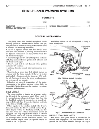
the left front door is open, the power lock/keyless en- Fig. 1 Chime Module Location
try systems will not operate.
Following are general descriptions of the major
components in the chime warning system. Refer to
Group 8W - Wiring Diagrams for complete circuit de-
scriptions and diagrams.
CHIME MODULE
The chime module is located on a bracket under
the left end of the instrument panel (Figs. 1 and 2).
It receives battery voltage at all times from fuse 8 in
the fuseblock module. It also receives a second bat-
tery feed through fuse 9 when the ignition switch is
in the ON or START position.
Other inputs to the module include the driver’s
door jamb switch, the driver’s seat belt switch, the ig-
nition key-in switch, the headlamp switch, and the
tone line from the vehicle information center (if
Fig. 2 Chime Module and Connector
equipped). The only output of the module is a timed
4 to 8 second feed to the seat belt reminder lamp in DRIVER’S DOOR JAMB SWITCH
the message center of the instrument cluster. The The driver’s door jamb switch is mounted to the
timer function begins after the ignition switch is driver’s door hinge pillar. The switch closes a path to
turned to the ON position. ground for the chime module through the key-in
2. 8U - 2 CHIME/BUZZER WARNING SYSTEMS ZJ
switch or headlamp switch when the driver’s door is mally closed, providing a ground path to the chime
opened, and opens when the driver’s door is closed. module. When the tip-half of the seat belt is inserted
This switch can not be repaired. If faulty, it must be into the seat belt buckle, the switch opens the chime
replaced. module ground path. The seat belt switch can not be
repaired. If faulty, the entire driver’s seat belt buck-
IGNITION KEY-IN SWITCH le-half must be replaced. Refer to Group 23 - Body
The key-in switch is integral to the ignition switch, Components for service procedures.
which is mounted on the right side of the steering
column. It closes a path to ground for the chime mod- VEHICLE INFORMATION CENTER TONE LINE
ule when the ignition key is inserted in the ignition If the vehicle is equipped with the optional Vehicle
lock cylinder and the driver’s door jamb switch is Information Center (VIC), an output from the VIC
closed (door open). The switch opens when the key is
provides a ground signal to the chime module when
removed from the ignition lock cylinder. This switch
it detects a fault. This signal causes the chime mod-
can not be repaired. If faulty, the entire ignition
ule to sound an audible signal to the driver. Refer to
switch must be replaced. Refer to Group 8D - Igni-
Group 8E - Instrument Panel and Gauges for more
tion Systems for service procedures.
information on the VIC system.
HEADLAMP SWITCH
The headlamp switch is located in the instrument
POWER DOOR LOCK INHIBIT
panel. It closes a path to ground for the chime mod- Pin 8 of the chime module provides the ground for
ule when the park or headlamps are on and the driv- the coil side of the power door lock relay. The LOCK
er’s door jamb switch is closed (door open). The function will not operate if:
switch opens the ground path when the park and • the chime module is not plugged in
headlamps are turned off. The headlamp switch can • the key is in the ignition lock cylinder, or exterior
not be repaired. If faulty, it must be replaced. Refer lamps are ON, while the left front door is open
to Group 8E - Instrument Panel and Gauges for ser- • the power door lock inhibit feature of the chime
vice procedures. module is inoperable due to defective electronics in
the chime module. (In this case, the power door lock
DRIVER’S SEAT BELT SWITCH operation is unpredictable.)
The driver’s seat belt switch is integral to the driv-
er’s seat belt buckle-half assembly. The switch is nor-
3. ZJ CHIME/BUZZER WARNING SYSTEMS 8U - 3
DIAGNOSIS
CHIME WARNING SYSTEM
If the chime module does not operate as described,
check the two fuses for pins 1 and 7 (Figs. 3, 4) and
replace as required. If the fuses are not defective,
perform the following tests to determine if the prob-
lem is in the module or in the wiring.
(1) Remove the module and replace with a known
good module. Now, check operation again. If the prob-
lem is not corrected by replacing the module, re-in-
stall original module and go to next step.
Fig. 4 Chime Module Terminal Identification
filament). If OK, go to next step. If not OK, repair
circuit to seat belt warning lamp or replace bulb as
required.
(5) Check resistance between chime module con-
nector pin 3 and a good ground. Meter should read
zero ohms. If OK, go to next step. If not OK, repair
circuit to ground as required.
(6) Check resistance between chime module con-
nector pin 4 and a good ground. Meter should read
zero ohms with left front seat belt unbuckled and
Fig. 3 Chime Module Connector Terminal open circuit with belt buckled. If OK, go to next step.
Identification If not OK, repair circuit to seat belt switch or replace
seat belt buckle half as required.
(2) Turn ignition switch to ON position. Measure
(7) Open left front door. Check resistance between
voltage at chime module connector pin 1. Meter
chime module connector pin 6 and a good ground.
should read battery voltage. If OK, go to next step. If Meter should read open circuit. Insert key ignition
not OK, repair circuit to ignition switch as required. lock cylinder and meter should read zero ohms. If
(3) Turn ignition switch to OFF and remove key OK, go to next step. If not OK, repair circuit to key-
from ignition lock cylinder. Measure voltage at chime in-ignition switch or replace key-in ignition switch as
module connector pin 7. Meter should read battery required.
voltage. If OK, go to next step. If not OK, repair cir- (8) Remove key from ignition lock cylinder. Open
cuit to fuseblock module as required. left front door and turn headlamp switch ON. Check
(4) Turn ignition switch to OFF position. Discon- resistance between chime module connector pin 6
nect battery negative cable. Check resistance be- and a good ground. Meter should read zero ohms. If
tween chime module connector pin 2 and a good OK, replace faulty chime module. If not OK, repair
circuit to headlamp switch or replace headlamp
ground. Meter should read almost zero ohms (bulb
switch as required.
5. ZJ CHIME/BUZZER WARNING SYSTEMS 8U - 5
Fig. 6 Halo Lamp And Key-In-Ignition Switch
Continuity Chart
SERVICE PROCEDURES
Service procedures for components of the chime • headlamp switch - refer to Group 8E - Instrument
warning system can be found in the appropriate Panel and Gauges
group as follows: • driver’s seat belt switch - refer to Group 23 - Body
• driver’s door jamb switch - refer to Group 8L - Components.
Lamps
• ignition key-in switch - refer to Group 8D - Igni-
tion Systems