Alia +91-9537192988-Experience the Unmatchable Pleasure with Model Ahmedabad ...
Exj 8 p
1. XJ POWER LOCK SYSTEMS 8P - 1
POWER LOCK SYSTEMS
CONTENTS
page page
GENERAL INFORMATION KEYLESS ENTRY SYSTEM . . . . . . . . . . .... 3
INTRODUCTION . . . . . . . . . . . . . . . . . . . . .... 1 REMOTE KEYLESS ENTRY RECEIVER . . . .... 5
POWER LOCK SYSTEM . . . . . . . . . . . . . . .... 1 REMOTE KEYLESS ENTRY TRANSMITTER ... 5
REMOTE KEYLESS ENTRY SYSTEM . . . . .... 1 SERVICE PROCEDURES
DESCRIPTION AND OPERATION REMOTE KEYLESS ENTRY RECEIVER
DOOR MODULE . . . . . . . . . . . . . . . . . . . . . . . . 2 PROGRAMMING . . . . . . . . . . . . . . . . . . . .... 6
POWER LOCK MOTOR . . . . . . . . . . . . . . . . . . . 2 REMOTE KEYLESS ENTRY TRANSMITTER
POWER LOCK SWITCH . . . . . . . . . . . . . . . . . . . 2 BATTERY REPLACEMENT . . . . . . . . . . . .... 6
REMOTE KEYLESS ENTRY RECEIVER . . . . . . . 2 REMOTE KEYLESS ENTRY TRANSMITTER
REMOTE KEYLESS ENTRY TRANSMITTER . . . 2 PROGRAMMING . . . . . . . . . . . . . . . . . . . .... 6
DIAGNOSIS AND TESTING REMOVAL AND INSTALLATION
DOOR MODULE . . . . . . . . . . . . . . . . . . . . .... 3 DOOR MODULE . . . . . . . . . . . . . . . . . . . . .... 6
POWER LOCK MOTOR . . . . . . . . . . . . . . . .... 5 POWER LOCK MOTOR . . . . . . . . . . . . . . . .... 7
POWER LOCK SYSTEM AND REMOTE REMOTE KEYLESS ENTRY RECEIVER . . . .... 8
GENERAL INFORMATION more information on the features and use of these
systems.
INTRODUCTION
Power locks are optional factory-installed equip- POWER LOCK SYSTEM
ment on these models. The power window system The power lock system allows all of the doors and
and the power mirror system are included on vehi- the liftgate to be locked or unlocked electrically by
cles equipped with the power lock option. On vehicles operating the switch on either front door trim panel.
equipped with the power lock option, all of the doors This system operates with battery power supplied
and the liftgate can be locked and unlocked electri- through a fuse in the junction block, independent of
cally by operating the switch on either front door the ignition switch.
trim panel. The power lock system includes a lock The power lock system includes the front door
inhibit feature, which prevents the doors from being power lock switches integral to the driver and pas-
locked by the power lock system if the driver door is senger door modules, and the power lock motors
open with the key in the ignition switch or with the mounted in each door and the liftgate. The power
headlamp switch in the On position. However, the lock control circuitry and the power lock and unlock
doors can still be locked manually. relays are integral to the Passenger Door Module
The Remote Keyless Entry (RKE) system is an (PDM).
additional option available on vehicles equipped with
the power lock option. On vehicles with the RKE REMOTE KEYLESS ENTRY SYSTEM
option, the power locks can also be operated by The Remote Keyless Entry (RKE) system is a radio
depressing the Lock or Unlock buttons of the RKE frequency system that allows the use of a remote
radio transmitter. The RKE system includes an illu- radio transmitter to control the power lock and illu-
minated entry feature, which turns on the courtesy minated entry systems. The RKE system consists of
lamps for a timed interval (about thirty seconds), the remote key fob transmitter and a radio receiver
when the power locks are unlocked using the RKE with program logic, which is installed in an RKE
transmitter. housing on the headliner of the vehicle, or in the
The power locks and RKE systems operate with housing of the optional overhead console, depending
battery power supplied independent of the ignition upon how the vehicle is equipped.
switch. Following are general descriptions of the The RKE system can retain the vehicle access
major components in the power lock, and RKE sys- codes of up to four transmitters. The transmitter
tems. Refer to 8W-61 - Power Door Locks in Group codes are retained in memory, even if the battery is
8W - Wiring Diagrams for complete circuit descrip- disconnected. If a transmitter is faulty or lost, new
tions and diagrams. Refer to the owner’s manual for transmitter vehicle access codes can be programmed
2. 8P - 2 POWER LOCK SYSTEMS XJ
GENERAL INFORMATION (Continued)
into the system using a DRB scan tool and the POWER LOCK MOTOR
proper Diagnostic Procedures manual. In the power lock and Remote Keyless Entry
The RKE system for this vehicle also features a (RKE) systems, the locks are actuated by a reversible
customer-programmable horn chirp feature. This fea- motor mounted within each door and the liftgate.
ture allows the customer the option of enabling or The power lock motor direction is controlled by the
disabling the horn chirp request that the RKE battery and ground feeds from the power lock and
receiver issues as an audible indication that a valid unlock relays integral to the Passenger Door Module
Lock signal has been received from the RKE trans- (PDM).
mitter. See Remote Keyless Entry Receiver Program- The power lock motors cannot be repaired and, if
ming in this group for more information on this faulty or damaged, the entire motor must be
feature. replaced.
REMOTE KEYLESS ENTRY TRANSMITTER
DESCRIPTION AND OPERATION
The Remote Keyless Entry (RKE) system transmit-
ter is equipped with two buttons, labeled Lock and
POWER LOCK SWITCH
Unlock. It is also equipped with a key ring and is
The power locks are controlled by a two-way switch
designed to serve as a key fob. The operating range
that is integral to the Driver Door Module (DDM)
of the transmitter radio signal is up to 7 meters (23
and the Passenger Door Module (PDM) mounted in
feet) from the RKE receiver.
the trim panel of its respective front door. Each
Each transmitter has a different vehicle access
switch is illuminated by a light-emitting diode when
code, which must be programmed into the memory of
the ignition switch is turned to the On position. The
the RKE receiver in the vehicle in order to operate
power lock switches provide a hard-wired lock or
the RKE system. Refer to the service procedure for
unlock signal to the power lock system control cir-
Remote Keyless Entry Transmitter Programming in
cuitry, which is located in the PDM.
this group for more information.
The power lock switches and their lamps cannot be
The transmitter operates on two Duracell DL2016
repaired. If the switches are damaged or faulty, the
(or equivalent) batteries. Typical battery life is from
entire PDM or DDM must be replaced.
one to two years. The transmitter cannot be repaired
and, if faulty or damaged, it must be replaced.
DOOR MODULE
A Driver Door Module (DDM) and a Passenger
REMOTE KEYLESS ENTRY RECEIVER
Door Module (PDM) are used on all models equipped
On models with the Remote Keyless Entry (RKE)
with power locks and power windows. Each door
option, an RKE receiver is mounted in an RKE hous-
module houses both the front power lock and power
ing, or in the overhead console housing on the vehicle
window switches. The DDM also houses individual
headliner. The RKE receiver is a radio frequency unit
switches for each passenger door power window, a
that also contains the RKE system program logic.
power window lockout switch and the power mirror
The RKE receiver also performs as a smart relay for
switch. The PDM also houses the control circuitry
the illuminated entry feature.
and the power lock and unlock relays for the power
The RKE receiver has a memory function to retain
lock system.
the vehicle access code of at least one, but no more
In its role as the power lock control module, the
than four transmitters. The receiver is designed to
PDM receives inputs from the battery, the ignition
retain the transmitter codes in memory, even if the
switch, the DDM, the driver door ajar switch, the
battery is disconnected.
key-in ignition switch, and the headlamp switch. It
The RKE module receives inputs from the battery,
also receives a hard-wired input from the RKE
the driver door ajar switch, and the Chrysler Colli-
receiver, if the vehicle is so equipped. In response to
sion Detection (CCD) data bus. It also receives the
these inputs, the PDM sends the proper outputs to
radio signal input from the RKE transmitter. In
control the power lock motors through its integral
response to those inputs, it is programmed to control
power lock and unlock relays.
outputs to the power lock motors, the courtesy lamp
The DDM and the PDM are mounted to their
circuits, and the vehicle horn.
respective front door trim panels. The DDM and
The RKE system for this vehicle also features a
PDM are serviced individually and cannot be
customer-programmable horn chirp feature. This fea-
repaired. If the DDM or PDM, or any of the switches
ture allows the customer the option of enabling or
and circuitry they contain are faulty or damaged, the
disabling the horn chirp request that the RKE
complete module must be replaced.
receiver issues as an audible indication that a valid
Lock signal has been received from the RKE trans-
3. CONNECTOR 2 (C2)
XJ POWER LOCK SYSTEMS 8P - 3
DESCRIPTION AND OPERATION (Continued)
mitter. See Remote Keyless Entry Receiver Program- (1) Disconnect and isolate the battery negative
ming in this group for more information on this cable. Remove the driver side front door trim panel
feature. and unplug the 12-way DDM wire harness connec-
The RKE receiver cannot be repaired and, if faulty tor (C-2) from the DDM. Check for continuity
or damaged, it must be replaced. between the ground circuit cavity of the 12-way
DDM wire harness connector and a good ground.
There should be continuity. If OK, go to Step 2. If
DIAGNOSIS AND TESTING not OK, repair the open circuit to ground as
required.
POWER LOCK SYSTEM AND REMOTE KEYLESS (2) If the problem being diagnosed is inoperative
ENTRY SYSTEM power lock switch illumination, proceed as follows.
On models without the Remote Keyless Entry If the problem is not power lock switch illumina-
(RKE) option, proceed directly to the Door Module tion, go to Step 4. Connect the battery negative
diagnosis. As a preliminary diagnosis for models with cable. Turn the ignition switch to the Accessory or
the RKE system, note the power lock system and On positions. Check for battery voltage at both
illuminated entry system operation while you actuate sides of the power window circuit breaker in the
both the Lock and Unlock functions with the power junction block. If OK, go to Step 3. If not OK,
lock switches and the RKE transmitter. Then, pro- replace the faulty circuit breaker.
ceed as follows: (3) With the ignition switch still in the On or
• If the entire power lock system fails to function Accessory position, check for battery voltage at the
with either the power lock switches or the RKE fused ignition switch output circuit cavity of the
transmitter, see the Door Module diagnosis in this 12-way DDM wire harness connector. If OK, replace
group. the faulty DDM. If not OK, repair the open circuit
• If the system functions with both power lock to the junction block as required.
switches, but not with the RKE transmitter, see the (4) Test the power lock switch continuity through
Remote Keyless Entry Transmitter diagnosis in this the DDM 12-way wire harness connector receptacle.
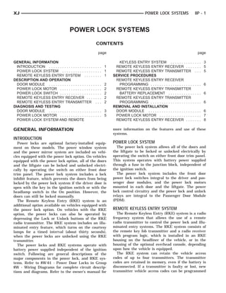
group. See the DDM Power Lock Switch Continuity chart
• If one power lock motor fails to operate with (Fig. 1) to determine if the continuity is correct in
both of the power lock switches and/or the RKE the Lock and Unlock switch positions. If OK, repair
transmitter, see the Power Lock Motor diagnosis in the lock request circuit and/or the unlock request
this group. circuit between the DDM and the PDM as required.
• If the RKE and power lock systems are function- If not OK, replace the faulty DDM.
ing, but the illuminated entry system fails to operate,
see the Remote Keyless Entry Receiver diagnosis in
this group.
DOOR MODULE
If the power lock system is inoperative with either
front door power lock switch, test the Passenger Door
Module (PDM). If the power lock system is inopera-
tive with only the driver side front door power lock
switch, test the Driver Door Module (DDM). For cir-
cuit descriptions and diagrams, refer to 8W-61 -
CONNECTOR 2 (C2)
Power Door Locks in Group 8W - Wiring Diagrams.
SWITCH POSITION CONTINUITY BETWEEN
DRIVER DOOR MODULE LOCK 7&8
The only function of the Driver Door Module UNLOCK 11 & 8
(DDM) in the power lock system is to provide a Lock
or Unlock signal to the power lock system control cir-
cuitry contained within the Passenger Door Module Fig. 1 DDM Power Lock Switch Continuity $$1$
(PDM). The DDM signals the PDM by providing a PASSENGER DOOR MODULE
hard-wired ground path through the DDM ground The Passenger Door Module (PDM) contains the
circuit and the driver side power lock switch contacts passenger side front door power lock switch and the
to the lock request or unlock request terminals of the power lock system control circuitry. In its role as a
PDM. The DDM power lock switch function can be power lock switch, it provides the power lock system
tested as follows: control circuitry with a ground path through the
PDM ground circuit and the driver side power lock
4. CONNECTOR 1 (C-1) (C-2)
CONNECTOR 2 $$2$
8P - 4 POWER LOCK SYSTEMS XJ
DIAGNOSIS AND TESTING (Continued)
switch contacts to indicate a lock request or unlock the On position. Check for continuity between the
request. door ajar/key-in circuit cavity of the 8-way PDM
In its role as the power lock control module, the wire harness connector and a good ground. There
PDM receives inputs from the battery, the ignition should be continuity. If OK, go to Step 8. If not OK,
switch, the DDM, the driver door ajar switch, the repair the open door ajar and/or key-in ignition cir-
key-in ignition switch, and the headlamp switch. It cuits as required. Refer to Group 8U - Chime/
also receives a hard-wired input from the RKE Buzzer Warning Systems for more information.
receiver, if the vehicle is so equipped. In response to (7) Connect the battery negative cable. Check for
these inputs, the PDM sends the proper outputs to battery voltage at the fused B(+) circuit cavity of
control the power lock motors through its integral the 8-way PDM wire harness connector. If OK, go to
power lock and unlock relays. The PDM power lock Step 8. If not OK, repair the open circuit to the fuse
system functions can be tested as outlined below. If in the junction block as required.
the power lock system operates, but the RKE system (8) Test the PDM power lock switch continuity
lock and/or unlock functions are inoperative, see the through the two PDM wire harness connector recep-
diagnosis for the Remote Keyless Entry Transmitter tacles. See the PDM Power Lock Switch Continuity
in this group. chart (Fig. 2) to determine if the continuity is cor-
(1) Check the fuse in the junction block. If OK, go rect in the Lock and Unlock switch positions. If OK,
to Step 2. If not OK, repair the shorted circuit or see the diagnosis for Power Lock Motors in this
component as required and replace the faulty fuse. group. If not OK, replace the faulty PDM.
(2) Disconnect and isolate the battery negative
cable. Remove the passenger side front door trim
panel and unplug the 8-way PDM wire harness con-
nector (C-1) from the PDM. Check for continuity
between the ground circuit cavity of the 8-way PDM
wire harness connector and a good ground. There
should be continuity. If OK, go to Step 3. If not OK,
repair the open circuit to ground as required.
(3) If the problem being diagnosed is inoperative
power lock switch illumination, proceed as follows. If
the problem is not power lock switch illumination, go
to Step 5. Connect the battery negative cable. Turn
the ignition switch to the Accessory or On positions.
Check for battery voltage at both sides of the power
window circuit breaker in the junction block. If OK,
go to Step 4. If not OK, replace the faulty circuit LEFT-HAND DRIVE (LHD)
breaker. SWITCH POSITION CONTINUITY BETWEEN
(4) With the ignition switch still in the Accessory
LOCK C1 PIN 3 & C1 PIN 6
or On positions, check for battery voltage at the
C1 PIN 3 & C2 PIN 1
fused ignition switch output circuit cavity of the
8-way PDM wire harness connector. If OK, replace C1 PIN 3 & C2 PIN 5
the faulty PDM. If not OK, repair the open circuit to UNLOCK C1 PIN 6 & C1 PIN 7
the junction block as required. C1 PIN 7 & C2 PIN 1
(5) If the problem being diagnosed is an inopera- C1 PIN 7 & C2 PIN 5
tive door lock inhibit feature or a power lock system
that responds to an Unlock command, but not a Lock
command, proceed as follows. Otherwise, go to Step RIGHT-HAND DRIVE (RHD)
7. With the driver side front door closed, check for SWITCH POSITION CONTINUITY BETWEEN
continuity between the door ajar/key-in circuit cavity LOCK C1 PIN 7 & C1 PIN 6
of the 8-way PDM wire harness connector and a good C1 PIN 7 & C2 PIN 1
ground. There should be no continuity. If OK, go to
C1 PIN 7 & C2 PIN 5
Step 6. If not OK, repair the shorted door ajar and/or
key-in ignition circuits as required. Refer to Group UNLOCK C1 PIN 6 & C1 PIN 3
8U - Chime/Buzzer Warning Systems for more infor- C1 PIN 3 & C2 PIN 1
mation. C1 PIN 3 & C2 PIN 5
(6) Open the driver side front door with the key in
the ignition switch or with the headlamp switch in Fig. 2 PDM Power Lock Switch Continuity
5. XJ POWER LOCK SYSTEMS 8P - 5
DIAGNOSIS AND TESTING (Continued)
POWER LOCK MOTOR NOTE: Be certain to perform the Remote Keyless
Before you proceed with this diagnosis, confirm Entry Transmitter Programming procedure again
proper power door lock switch operation. See Door following this test. This procedure will erase the
Module in this group for the diagnostic procedures. access code of the test transmitter from the RKE
Remember, the Passenger Door Module (PDM) cir- receiver.
cuitry controls the output to each of the power lock
motors. For circuit descriptions and diagrams, refer
to 8W-61 - Power Door Locks in Group 8W - Wiring REMOTE KEYLESS ENTRY RECEIVER
Diagrams. If the problem being diagnosed is an inoperative
(1) Check each power lock motor for correct opera- RKE horn chirp feature, be certain that the horn
tion while moving the power lock switch to both the chirp feature has not been disabled by performing
Lock and Unlock positions. If all of the power lock the Remote Keyless Entry Receiver Programming
motors are inoperative, go to Step 2. If one power procedure as described in this group. Also be certain
lock motor is inoperative, go to Step 3. that the vehicle horn system is operational. See
(2) If all of the power lock motors are inoperative, Group 8G - Horn Systems for more information.
the problem may be caused by one shorted motor. If the problem being diagnosed is an inoperative
Unplugging a shorted power lock motor from the RKE illuminated entry system, be certain that the
power lock circuit will allow the good power lock interior courtesy lamp system is operational. See
motor to operate. Unplug each power lock motor wire Group 8L - Lamps for more information.
harness connector, one at a time, and recheck both Before you proceed with diagnosis of the RKE
the lock and unlock functions by operating the power receiver, see the diagnosis for Remote Keyless Entry
lock switch. If all of the power lock motors are still Transmitter in this group. For circuit descriptions
inoperative after the above test, check for a short or and diagrams, refer to 8W-61 - Power Door Locks in
open circuit between the power lock motors and the Group 8W - Wiring Diagrams.
PDM. If unplugging one power lock motor causes the (1) Check the fuses in the Power Distribution Cen-
other motors to become functional, go to Step 3 to ter (PDC) and the junction block. If OK, go to Step 2.
test the unplugged motor. If not OK, repair the shorted circuit or component as
(3) Once it is determined which lock motor is inop- required and replace the faulty fuse.
erative, that motor can be tested as follows. Unplug (2) Disconnect and isolate the battery negative
the wire harness connector at the inoperative motor. cable. Remove the Remote Keyless Entry (RKE)
Apply 12 volts to the motor terminals to check its receiver as described in this group. Unplug the wire
operation in one direction. Reverse the polarity to harness connector from the RKE receiver.
check the operation in the other direction. If OK, (3) Check the wire harness connector and the
repair the short or open circuits to the PDM as receptacle in the receiver for loose, corroded, or dam-
required. If not OK, replace the faulty power lock aged terminals and pins. If OK, go to Step 4. If not
motor. OK, repair as required.
(4) Check for continuity between each of the two
REMOTE KEYLESS ENTRY TRANSMITTER ground circuit cavities of the RKE receiver wire har-
(1) Replace the Remote Keyless Entry (RKE) ness connector and a good ground. In each case,
transmitter batteries as described in this group. Test there should be continuity. If OK, go to Step 5. If not
each of the transmitter functions. If OK, discard the OK, repair the circuit to ground as required.
faulty batteries. If not OK, go to Step 2. (5) Connect the battery negative cable. Check for
(2) Perform the Remote Keyless Entry Transmitter battery voltage at each of the two fused B(+) circuit
Programming procedure with the suspect transmitter cavities of the RKE receiver wire harness connector.
and another known good transmitter using a DRB If OK, go to Step 6. If not OK, repair the open circuit
scan tool, as described in the proper Diagnostic Pro- to the PDC or the junction block as required.
cedures manual. (6) If the problem being diagnosed involves only
(3) Test the RKE system operation with both the RKE horn chirp feature, go to Step 10. If the
transmitters. If both transmitters fail to operate the problem being diagnosed involves only the RKE illu-
power lock system, see the diagnosis for the Remote minated entry feature, go to Step 9. If the problem
Keyless Entry Receiver in this group. If the known being diagnosed involves only the RKE power locks
good transmitter operates the power locks and the feature, go to Step 7.
suspect transmitter does not, replace the faulty (7) Disconnect and isolate the battery negative
transmitter. cable. Unplug the 8-way Passenger Door Module
(PDM) wire harness connector. Check for continuity
between the lock request circuit cavity of the RKE
receiver wire harness connector and a good ground.
6. 8P - 6 POWER LOCK SYSTEMS XJ
DIAGNOSIS AND TESTING (Continued)
Repeat the test between the unlock request circuit requires the use of a DRB scan tool. Refer to the
cavity of the RKE receiver wire harness connector proper Diagnostic Procedures manual for more infor-
and a good ground. In each case, there should be no mation.
continuity. If OK, go to Step 8. If not OK, repair the
shorted circuit as required. REMOTE KEYLESS ENTRY RECEIVER
(8) Check for continuity between the lock request PROGRAMMING
circuit cavities of the RKE receiver wire harness con- The optional Remote Keyless Entry (RKE) system
nector and the 8-way PDM wire harness connector. for this vehicle has a customer-programmable horn
Repeat the test between the unlock request circuit chirp feature. The horn chirp is requested by the
cavities of the RKE receiver wire harness connector RKE receiver through a hard-wired circuit to the
and the 8-way PDM wire harness connector. In each horn relay whenever a valid Lock message is
case, there should be continuity. If OK, replace the received from a programmed RKE radio transmitter.
faulty RKE receiver. If not OK, repair the open cir- The purpose of the horn chirp is to provide the
cuit as required. vehicle operator with an audible verification that the
(9) Check for continuity between the door ajar cir- Lock request has been received by the RKE receiver.
cuit cavity of the RKE receiver wire harness connec- However, for any TENERnumber of reasons, some customers
U-NUTPUSH-IN FAS- DOORRIM PANEL
T
tor and a good ground with the driver door closed. may prefer that this feature be disabled. This RKE
There should be no continuity until the driver door is system allows them that option.
opened. If OK, replace the faulty RKE receiver. If not To program the Remote Keyless Entry (RKE)
OK, repair the circuit or replace the faulty driver receiver to disable the horn chirp feature, proceed as
door ajar switch as required. follows:
(10) Unplug the horn relay from the junction (1) Press and hold the Lock button of a pro-
block. Check for continuity between the horn relay grammed RKE transmitter depressed for five to ten
output circuit cavity of the RKE receiver wire har- seconds.
ness connector and a good ground. There should be (2) While holding the RKE transmitter Lock but-
no continuity. If OK, go to Step 11. If not OK, repair ton depressed, press and release the RKE transmit-
the short circuit to the horn relay as required. ter Unlock button.
(11) Check for continuity between the horn relay (3) The horn chirp feature is now disabled.
output circuit cavity of the RKE receiver wire har- Repeating the preceding steps will again enable
ness connector and the junction block cavity for the the horn chirp feature.
horn relay coil ground terminal (85). There should be
continuity. If OK, replace the faulty RKE receiver. If
not OK, repair the open circuit to the junction block REMOVAL AND INSTALLATION
as required.
DOOR MODULE
(1) Disconnect and isolate the battery negative
SERVICE PROCEDURES cable.
(2) Remove the screws that secure the door trim
REMOTE KEYLESS ENTRY TRANSMITTER panel to the inner door panel (Fig. 3).
BATTERY REPLACEMENT
To replace the Remote Keyless Entry (RKE) trans-
mitter batteries, separate the transmitter case halves
at the center seam by prying gently with a trim
stick, or another suitable wide flat-bladed tool. The
case snaps open and shut.
Replace the two batteries with new Duracell
DL2016, or their equivalent. Be certain that the bat-
teries are installed with their polarity correctly ori-
ented. Then, align the two transmitter case halves
with each other, and squeeze them firmly together
until they snap back into place.
REMOTE KEYLESS ENTRY TRANSMITTER
PROGRAMMING
To program the Remote Keyless Entry (RKE)
transmitter access codes into the RKE receiver Fig. 3 Front Door Trim Panel Remove/Install
7. INSIDEDOOR TRIM PANEL
LOCK REMOTELATCH AND
DOOR CONTROLS SCREWS CONNECTOR 2 RECEP- CLE
CONNECTOR DOOR
1 TACLE
MODULE
RECEPTA- TRIM PANEL PUSH NUT
PLUG ASSIST HANDLE LIFTGATE
XJ POWER LOCK SYSTEMS 8P - 7
REMOVAL AND INSTALLATION (Continued)
(3) Using a trim stick or another suitable wide must be replaced. Refer to Group 23 - Body for the
flat-bladed tool, gently pry the trim panel away from rear door latch service procedures.
the door around the perimeter to release the trim
panel retainers. LIFTGATE
(1) Disconnect and isolate the battery negative
NOTE: To aid in the removal of the trim panel, start cable.
at the bottom of the panel. (2) Open the liftgate.
(3) Using a trim stick or another suitable wide
(4) Lift the door trim panel upwards and away flat-bladed tool, gently pry the two screw cover plugs
from the door to disengage the top of the panel from out of the liftgate assist handle.
the inner belt weatherstrip. (4) Remove the two screws that secure the liftgate
(5) Pull the door trim panel away from the inner assist handle to the liftgate inner panel (Fig. 5).
door far enough to access the inside door latch
release and lock linkage rods near the back of the
inside door remote controls.
(6) Unsnap the plastic retainer clips from the
inside door remote control ends of the latch release
and lock linkage rods, and remove the rod ends from
the inside door remote controls.
(7) Unplug the wire harness connectors from the
door module.
(8) Remove the front door trim panel from the
vehicle.
(9) Remove the three screws that secure the door
module to the door trim panel (Fig. 4).
Fig. 5 Liftgate Trim Panel Remove/Install
(5) Remove the eight screws that secure the lift-
gate trim panel to the liftgate inner panel on both
sides and above the liftgate glass.
(6) Using a trim stick or another suitable wide
flat-bladed tool, gently pry the lower edges of the
trim panel away from the liftgate inner panel around
the perimeter to release the trim panel retainers.
NOTE: To aid in the removal of the trim panel, start
Fig. 4 Door Module Remove/Install at the bottom of the panel.
(10) Remove the door module from the trim panel.
(11) Reverse the removal procedures to install. (7) Remove the liftgate trim panel from the vehicle.
Tighten the mounting screws to 2.2 N·m (20 in. lbs.). (8) Reach through the liftgate inner panel access
hole and disconnect the link from the clip on the
POWER LOCK MOTOR power lock motor (Fig. 6).
(9) Remove the two screws that secure the power
FRONT DOOR lock motor to the liftgate inner panel.
The front door power lock motor is integral to the (10) Pull the power lock motor out through the lift-
front door latch unit. If the front door power lock gate inner panel access hole far enough to reach the
motor is faulty or damaged, the entire latch unit wire harness connector.
must be replaced. Refer to Group 23 - Body for the (11) Unplug the wire harness connector from the
front door latch service procedures. power lock motor.
(12) Remove the power lock motor from the lift-
REAR DOOR gate.
The rear door power lock motor is integral to the (13) Reverse the removal procedures to install.
rear door latch unit. If the rear door power lock Tighten the power lock motor mounting screws to 3
motor is faulty or damaged, the entire latch unit N·m (28 in. lbs.).
8. CONNECTORSSCREW LIFTGATE INNER PANEL
MOTOR LINK LOCK
CLIPS LEVER
8P - 8 POWER LOCK SYSTEMS XJ
REMOVAL AND INSTALLATION (Continued)
(6) Remove the RKE mini-dome unit from the
vehicle.
(7) Remove the two screws that secure the RKE
receiver circuit board to the mini-dome housing.
(8) Remove the RKE receiver circuit board from
the mini-dome housing.
OVERHEAD CONSOLE MOUNTED TYPE
(1) Disconnect and isolate the battery negative
cable.
(2) Remove the two screws located forward of the
display module that secure the overhead console to
the upper windshield opening reinforcement (Fig. 8).
Fig. 6 Liftgate Power Lock Motor Remove/Install
REMOTE KEYLESS ENTRY RECEIVER
MINI-DOME MOUNTED TYPE
(1) Disconnect and isolate the battery negative
cable.
(2) Remove the two screws that secure the Remote
Keyless Entry (RKE) mini-dome housing to the roof
panel reinforcement (Fig. 7).
Fig. 8 Overhead Console Remove/Install
(3) To release the overhead console from the rear
mounting bracket, use your fingertips to gently pull
the sides of the overhead console housing outward
near the rear mounting bracket.
(4) Move the overhead console forward to disen-
gage the rear mounting tab from the headliner.
(5) Lower the overhead console far enough to
access the two wire harness connectors.
(6) Unplug one wire harness connector near the
push button module towards the front of the over-
head console.
(7) Unplug one wire harness connector from the
Remote Keyless Entry (RKE) receiver near the center
of the overhead console.
Fig. 7 Mini-Dome Housing Remove/Install (8) Remove the overhead console from the vehicle.
(9) Remove the six screws that secure the rear
(3) Lower the front of the mini-dome housing and
overhead console housing to the overhead console
slide the unit forward to disengage the rear mount-
bezel (Fig. 9).
ing tab from the headliner.
(10) Gently flex the sides of the overhead console
(4) Lower the mini-dome housing far enough to
bezel far enough to clear the tabs on the rear console
reach the RKE receiver wire harness connector.
housing and remove the housing from the bezel.
(5) Unplug the wire harness connector from the
RKE receiver.
9. REAR OVERHEAD CONSOLE
OVERHEAD SCREWSBEZEL
HOUSING
CONSOLE TABS RECEIVER
RKE
XJ POWER LOCK SYSTEMS 8P - 9
REMOVAL AND INSTALLATION (Continued)
(12) Remove the RKE circuit board from the rear
overhead console housing.
(13) Reverse the removal procedures to install.
Fig. 9 RKE Receiver Remove/Install
(11) Remove the two screws that secure the RKE
receiver circuit board to the rear overhead console
housing.