1. NEW!
Fluke Ti25 and Ti10
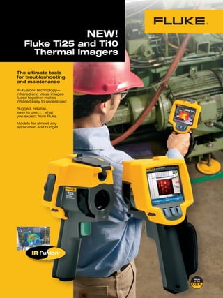
Thermal Imagers
The ultimate tools
for troubleshooting
and maintenance
IR-Fusion® Technology—
infrared and visual images
fused together makes
infrared easy to understand
Rugged, reliable,
easy to use . . . what
you expect from Fluke
Models for almost any
application and budget
2. IR-Fusion—multiple viewing modes
Find it, fix it, fast! Identify problems quickly using different on-screen modes—
the user selects the mode that works best for each situation.
While some viewing modes are not included in every model,
all are available for viewing and analysis in the included free
SmartViewTM software.
The versatility
of thermal imaging
Applications Thermal imaging is a non-contact
Temperature changes can technology that measures infrared
indicate problems in many wavelengths to determine temperatures
areas you see everyday, some from a safe distance.
include:
A thermal imager displays an image that
• Inside electrical uses different colors to represent different
Tank level too low
distribution and service
(switch gear, panels,
temperatures. This image makes it quick and
Full (traditional) IR Full screen Full Visual (Visible light)
controls, fuses, transformers, easy to visually check surface temperatures infrared view for maximum Image A digital photographic
receptacles, lighting, and identify hot spots. Hot spots or a rise in infrared detail. image, as you would get from a
conductors, overhead buses, temperature often indicate that a problem exists digital camera.
motor control centers) or a failure could be imminent.
• Motors, pumps and Until recently, thermal imaging was complex
mechanical (electric motors and expensive, keeping it in the domain of
and generators, pumps, thermography specialists. Fortunately, recent
compressors, evaporators, advances in technology and Fluke engineering
bearings, couplings, have not only lowered the costs but also made
gearboxes, gaskets/seals, imagers easier to use and practical as an
belts, rollers, disconnects) Abnormal uneven heating on motor
everyday troubleshooting tool in harsh work
• Process (tanks and vessels, environments.
pipes, valves and traps,
reactors, process insulation)
• HVAC/R (air conditioning, Diagnostic power—
heating, air handlers, the data behind the picture Automatic Blend A blend of the Picture-in-Picture Creates an IR
visual (visible light) and infrared ‘window’ surrounded by a visual
refrigeration)
All Fluke thermal imagers are fully radiometric. image together to create a single (visible light) frame to easily
• Outside electrical These units not only graphically display image for optimal viewing. Easy identify problems, while main-
distribution for utilities menu options give you access to taining a frame of reference with
temperature differences, they also measure and
(transformers, bushings, the different blending options surroundings.
insulators, transmission lines, store temperatures at every point in the image. from full thermal image to full
other exterior conductors, All these data points can be recalled and used visual image. Automatic blend
service connections, for detailed analysis of a potential problem or provides enhanced detail to help
disconnects, capacitor banks) just monitoring trends over time of the same Overheating bearing cap IR-Fusion® Technology* locate problems precisely along
with a visual frame of reference
Product specification matrix location. and helps to better focus the
on page 7 Whether you work in an industrial, electrical See things both ways—Infrared and visual image.
or commercial facility you can discover if and (visible light) images fused together com-
where a problem exists quickly and easily municating critical information faster and
before contact measurements even need to easier—traditional infrared images are no
be made. longer enough.
Patent-pending IR-Fusion Technology,
®
only available on Fluke thermal imagers,
simultaneously captures a digital photo in
addition to the infrared image and fuses it IR/Color Alarm Displays only
temperatures falling above,
Fluke Thermal Imagers help you find together taking the mystery out of IR image below, or in between a user-
Three-phase switchgear
energy saving opportunities. load imbalance
analysis. selected range in infrared, and
Unexpected temperature differentials can Images enhanced with IR-Fusion help anything outside the selected
indicate where opportunities exist to increase identify and report suspect or faulty compo- range as a visual (visible light)
efficiency and save money. nents, enabling repairs to be done, and proving image.
that the problem was corrected effectively.
Faulty steam traps are easy to detect
with thermal imaging and if not
repaired can consume excess energy. *Patent-pending IR-Fusion Technology from Fluke links the infrared image to full
Once fixed, energy savings can be visual (visible light) image automatically. No need to carry a digital camera or
significant. spend additional time and energy to manage the infrared and visual images.
IR-Fusion links the two images together to make image management effortless.
2 3
3. The perfect thermal imagers for
everyday troubleshooting
Speaker for
Visual camera lens sound and
voice annotation
Protective playback
lens cover
The Fluke Ti25 and Ti10 are the perfect • Intuitive, three-button menu is easy to use . . . Large, landscape format
tools to add to your problem solving simply navigate with the push of a thumb. LCD display Microphone
2 GB SD
arsenal. Built for tough work environments,
these high-performance, fully radiometric
• No need to carry pen and paper—record memory for voice
annotation
findings by speaking into the camera. Voice card slot
imagers are ideal for troubleshooting annotations can be recorded with every
electrical installations, electro-mechanical image you take. Voice comments are saved
equipment, process instrumentation, HVAC along with individual images for future Picture-in-
equipment and others. reference (Ti25 only) picture, full
IR or blended
• Enhanced problem detection and analysis
• Store more than 3,000 screen images high-quality
capabilities with IR-Fusion® Technology. (.bmp format) for easy reporting direct into image
Simply scroll through the different viewing Microsoft Word® and other programs or 1,200
modes quickly to better identify trouble areas IR-Fusion images, including thermal image,
in Full IR thermal or Automatic (auto) Blend visual image, temperature data and voice
visual and thermal images. recorded comments for reporting and analysis
• Optimized for field use in rough work purpose. Data is stored on included 2 GB SD
environments. memory card.
- Engineered and tested to withstand a
2 meter (6.5 foot) drop—when was the last Easy to use
time you dropped a tool? three-button
menu
- Withstands dust and water-tested to an
IP54 rating AC adapter
terminal
- Innovative protective lens cover protects the
lens when not in use. The cover is securely Thermal
attached and out of the way while images imager lens
are being taken. Focus ring
- Works in ambient temperatures as low as
-10 ºC (14 °F) and high as +50 ºC (122 °F),
and the Ti25 measures up to 350 ºC (662 °F) Image capture
trigger
• Delivers the clear, crisp images needed to find
problems fast
- Identify even small temperature differences
that could indicate problems with excellent
Rugged, withstands
thermal sensitivity (NETD) 2 m (6.5 ft) drop
- High performance, low noise sensor
Wrist strap
provides high quality image and stable (adjusts for
temperature reading right or left
handed use)
- The smallest details become visible
with the large, widescreen full VGA color
LCD display
Fluke SmartViewTM software SmartViewTM software system
is included with each Fluke requirements
thermal imager.
• Powerful, modular suite of software tools for • Windows® 2000 SP4 with update rollup 1/XP SP2/
Vista
viewing, annotating, editing and analyzing of
infrared images. • A web browser for product registration. Internet
• Full support of IR-Fusion Technology lets you edit • Explorer 5.0 or newer or Netscape® 5.0 or newer
images in five viewing modes. • 500 MB available disk space, not counting space
• Robust analysis and reporting capabilities—no requirements for web browser
need to upgrade to expensive software solutions • 16-bit color, 800 x 600 resolution video or better
• Unlicensed—your entire team can load and use • Color printer for printing the images
the software. • CD-ROM drive (for installing SmartView software)
• Free upgrades for the life of your product
4 5
4. Thermal imaging Specifications
terminology explained
Fluke Ti25 Fluke Ti10
Palette - Color representation of the Imaging performance
temperatures (temperature scale) in a displayed Thermal: Field of View (FOV) 23° horizontal x 17° vertical
image. Certain color palettes meet personal Ironbow Minimum focus distance Thermal lens: 15 cm (approx. 6 in), Visible (visual) light lens: 46 cm (approx. 18 in)
preferences or optimize the image for different Thermal sensitivity (NETD) ≤ 0.1 °C at 30 °C (100 mK) ≤ 0.2 °C at 30 °C (200 mK)
applications and/or problems. An example of the
Minimum span (Auto/Manual) 5 °C/2.5 °C 10 °C/5 °C
different palettes appear to the right.
Focus Manual
Sensor Size - Similar to digital cameras the Detector size 160 x 120
sensor size describes the amount of displayed
Visual: On camera operating modes Picture-in-Picture (Blending is user selectable Full Picture-in-Picture and full screen IR
points per image of a thermal imager. A sensor between MAX, MID and MIN) and full
size of 160 x 120 captures and displays more Blue-red screen IR (Blending is user selectable
than 19,000 measurement points with each between MAX, MID and MIN)
measurement. This is more than sufficient for Visual (Visible light) camera 640 x 480 pixels, full color
almost all industrial and electrical applications. Temperature measurement
If the imager is fully radiometric then it also Temperature range -20 °C to +350 °C (-4 °F to +662 °F), 2 ranges -20 °C to +250 °C (-4 °F to +482 °F)
truly measures and stores all captured points
Accuracy ± 2 °C or 2 % (whichever is greater) ± 5 °C or 5 % (whichever is greater)
with the image.
Measurement modes Center point and hot and cold markers Center point
Field of view (FOV) - The total area, at a given On-screen emissivity correction Yes No
High contrast
distance, that your imager can see or detect.
Image presentation
Spatial Resolution (IFOV) is the smallest object
Digital display 9.1 cm (3.6 in) diagonal landscape color VGA (640 x 480) LCD
or area, at a given distance, that your imager
can detect and obtain an accurate temperature LCD backlight Selectable bright or auto
measurement within the Field of View. Pallettes Ironbow, blue-red, high contrast, Ironbow, blue-red, high contrast, grey
For help determining the FOV and IFOV for amber, hot metal, grey
your specific imager at selected distances go Image and data storage
to www.fluke.com/FOV. Amber Fully radiometric Yes
Thermal sensitivity - Indicates what the Storage medium 2 GB SD card stores up to 3000 .bmp IR images or 1200 .IS2 IR-Fusion images
smallest temperature difference is which can File formats supported Exportable to JPEG, BMP, GIF, PNG, TIFF, WMF EXIF, and EMF
be measured/displayed in an image. It basically Voice memo recorder Yes No
is the maximum resolution of the image and (voice annotation)
is referred to as NETD (noise equivalent Software SmartView; Full analysis and reporting software included
temperature difference). A NETD of 200 mK is Controls and adjustments
more than adequate for most industrial and Set-up controls Date/time,˚C/˚F, language, emissivity, hot spot Date/time,˚C/˚F, language
electrical applications. Hot metal and cold spot on image
Emissivity adjustment - All surfaces emit Language selection English, German, French, Spanish, Portuguese, Italian, Swedish, Finnish, Russian, Czech,
Polish, Turkish, Simplified Chinese, Traditional Chinese, Korean, Japanese
infrared energy or heat. The level of emission
varies much per surface and is described with Image controls Smooth auto scaling and manual scaling
the term emissivity. Painted coatings and On-screen indicators Battery status, real time clock and center point temperature, range and
materials usually have a high emissivity while span indication and high and low alarm settings
polished aluminum has a low emissivity Power
Visit www.fluke.com/emissivity for a table Grey Battery type Internal rechargeable battery (included)
with emissivities for different materials. If you Battery operating time up to 4 hours continuous operation
perform qualitative inspections with the imager Battery charging 2 hours with ac charger or dc car charger (charges battery while operating)
(most applications) then emissivity does not AC operation AC adapter/charger 110/230 V ac, 50/60 Hz
have to be adjusted. To measure the temperature
Power saving Automatic shutdown and sleep modes
of a material accurately it will be necessary to
Enviromental and mechanical design
adjust for the material’s emissivity in specific
applications. Operating temperature -10 °C to +50 °C (+14 °F to +122 °F)
Span - The set of temperature values that can Storage temperature -20 °C to +50 °C (-4 °F to +122 °F)
be measured within a preset range. Adjusting Relative humidity Operating and storage 10 % to 90 %, non-condensing
the span allows you to see more subtle Water and dust resistant IP54
temperature gradients (or contrast) in a captured Two meter (6.5 feet) drop test Yes
image. When the span is optimized the imager Protective lens cover Yes
shows 256 different shades of color in an image.
Weight (including battery) 1.2 kg (2.6 lbs)
Imager size (HxWxD) 267 mm x 127 mm x 152 mm (10.5 in x 5.0 in x 6.0 in)
Other
Warranty Two-years
EN 61010-1 2nd edition and EN61326-1 Yes
Country of manufacture U.S.A.
6 7