Reference list EXTERNAL USE Xylem in irrigation and agriculture
Hydrovar Retrofit
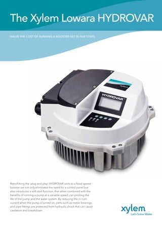
1. HALVE THE COST OF RUNNING A BOOSTER SET IN FIVE STEPS.
The Xylem Lowara HYDROVAR
Retrofiitting the ‘plug and play’ HYDROVAR units to a fixed speed
booster set not only eliminates the need for a control panel but
also introduces a soft start function, that when combined with the
benefits of running a pump at a variable speed, can prolong the
life of the pump and the water system. By reducing the in-rush
current when the pump is turned on, parts such as motor bearings
and pipe fittings are protected from hydraulic shock that can cause
cavitation and breakdown.
2. 2
3
Step Two: Clamping the HYDROVAR
into place.
The HYDROVAR sits directly onto the pump
and utilises the cool air emitted from the fan
vents to prevent overheating. This means
that there is no need for an additional
cooling unit, keeping the footprint of the
HYDROVAR to a minimum and not utilising
valuable wall space. Fixings are located
on the outer casing so no need to remove
the casing of the HYDROVAR as previous
models. Use the four mounting clamps
provided together with the central post
pin and secure it to the metal fan cowl of
the pump unit. The clamps are designed
to fit all IEC motors. Stainless steel ring
supports are available for motors fitted with
plastic fan cowls. Wall mounted versions are
available as an option.
Step Three: Pump Terminal Wiring.
After attaching the cable glands to the
exposed gland plate on the left hand side
of the HYDROVAR, unscrew and remove
the front of the pump motor terminal
box. Take the HYDROVAR connection
cables (purchased separately or made
using standard wires and connections)
and feed the motor terminal end of the
cable through the cable entry points,
connecting it to the relevant terminals. If
you are retrofitting the unit to an existing
booster set then the power supply
needs to be rerouted directly into the
HYDROVAR. No PCT is required and
this is now done by the internal software
of the HYDROVAR. Once this is done,
reattach the terminal front cover, ensuring
that the water seal is correctly in place.
4
Step Four: HYDROVAR wiring.
Remove the wiring chamber cover and
pass the other end of the connection
cable through the cable inlet on the left
hand side of the HYDROVAR, connecting
it to the relevant power supply and signal
wires. Once this is done, connect the
transducer cable (also called the sensor
or pressure transmitter) to the HYDROVAR
through the same gland plate. The loose
end of the transducer must then be
connected to the pipe as close to the
pump as possible.
5
Step Five: Completion
and programming.
After replacing the terminal cover lid
of the HYDROVAR unit, programme
the required bar pressure using the
buttons and the screen. Depending on
the number of pumps in the booster set,
some very simple programming may
be required. This is detailed clearly in
the operating instructions manual. The
first screen after powering up the unit
will be the quick start guide after setting
these parameters; the HYDROVAR will
automatically begin its soft start and work
to the system requirements.
1
A
E
B
F
C
G
D
H
Step One: Assessment of the installation
site and the current pump activity.
Before any HYDROVAR installation,the
site and its current equipment should be
assessed to determine the current level of
energy being consumed and the kW of the
motor.From here,the installer can calculate
how much the booster set or heating pump
is costing on an annual basis by calculating
0.22 Euros per hour for each kilowatt of
energy consumed. An 11kW single pump
will therefore cost €2.42 per hour to run at full
speed.Once this cost has been multiplied
by the number of pumps that are in use,the
installer can explain in monetary terms what
an average 50 per cent reduction in energy
consumption would save the end user.
Connecting a HYDROVAR couldn’t be simpler; here we demonstrate
an installation in just five steps: