Sample Wall Shop Drawings
•
3 j'aime•5,037 vues

This document provides details for the construction of a cold-formed steel framed structure. It includes general notes, material specifications, job site requirements, and panel assembly instructions. The general notes specify the scope, referenced standards, and responsibilities of designers and installers. Material specifications define the steel sheet, studs, tracks and other components to be used. Job site requirements address delivery, handling, storage, field modifications and repairs. Panel assembly instructions provide the sequence and steps for setting up wall panels, tying sections together, and attaching the top plates.

Recommandé
Contenu connexe
Tendances
Tendances (20)
En vedette
En vedette (16)
Similaire à Sample Wall Shop Drawings
Similaire à Sample Wall Shop Drawings (20)
Plus de Geoffrey Jennings
Dernier
Dernier (20)
Sample Wall Shop Drawings
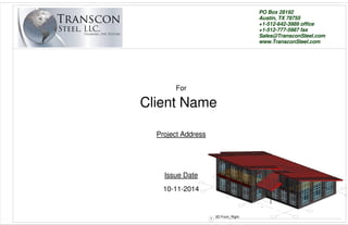
- 1. PO Box 28192 Austin, TX 78755 +1-512-642-3989 office +1-512-777-5987 fax Sales@TransconSteel.com www.TransconSteel.com For Project Address Issue Date Client Name 10-11-2014 1 3D Front_Right
- 2. Scale Project number DateDrawn by Size 11X17 TRANSCON Drawing number Checked By STEEL FRAMING THE FUTURE PO Box 2892 Austin, TX 78755 USA +1-512-642-3989 office +1-512-777-5987 fax Sales@TransconSteel.com Approved By 0.2 General Notes14-137 10/30/2014GMJ GMJ A. GENERAL A1. Scope In the absence of specific instructions to the contrary in the contract documents, the trade practices that are defined in this Code of Standard Practice shall govern the design, fabrication and installation of cold-formed steel structural framing. A2. Referenced Documents 1. AISI, Standard for Cold-Formed Steel Framing - General Provisions, 2004 Edition, American Iron and Steel Institute, Washington, DC. 2. AISI, Standard for Cold-Formed Steel Framing - Wall Stud Design 2004 Edition plus IBC 2006, American Iron and Steel Institute, Washington, DC. 3. AISI, Standard for Cold-Formed Steel Framing - Truss Design, 2004 Edition, American Iron and Steel Institute, Washington, DC. 4. ASTM, A1003/A1003M-02a, Standard Specification for Sheet Steel, Carbon, Metallic and Non- Metallic Coated for Cold-Formed Framing Members, ASTM International, West Conshohocken, PA. 5. ASTM, A780-01, Standard Practice for Repair of Damaged and Uncoated Areas of Hot-Dip Galvanized Coatings, ASTM International, West Conshohocken, PA. 6. ASTM C645-04, Standard Specification for Nonstructural Steel Framing Members, ASTM International, West Conshohocken, PA. 7. ASTM C754-00, Standard Specification for Installation of Steel Framing Members to Receive Screw-Attached Gypsum Panel Products, ASTM International, West Conshohocken, PA. 8. ASTM, C955-03, Standard Specification for Load-Bearing (Transverse and Axial) Steel Studs,Runners (Tracks), and Bracing or Bridging for Screw Application of Gypsum Panel Products and Metal Plaster Bases, ASTM International, West Conshohocken, PA. 9. SSMA, Product Technical Information, 2001 Edition, Steel Stud Manufacturers Association, Chicago, IL. A3. Responsibility for Design A3.1 The design professionals of record are responsible for the suitability and adequacy of all aspects of design. The design professionals and/or the owner shall have a right to solicit designs, plans, specifications and/or datafrom the component manufacturer, installer and/or specialty designer, but the responsibility for the safety of the structure, property and conformance to applicable building codes and standards remains with the design professionals of record. A3.2 If the contract documents require that the installer and/or specialty designer prepare designs, plans and/or specifications, the contract documents shall state clearly and precisely the exact requirements,including all applicable building codes and design requirements and all other regulatory requirements. The design professional of record assumes the responsibility for these designs. The design professionals of record shall confirm that the effect of the specialty designer's work conforms to the intent of the structural engineer of record on the overall project. The design professional of record shall coordinate the work of all the specialty designers with the design professionals' work and/or that of other specialty designers to ensure compatibility and integrate the connection and conformity of the components designed by the different specialty designers. This coordinationincludes, but is not limited to, addressing the forces and reactions as identified by the specialty designer that are transmitted to those elements of the structure that are not designed by the specialty designer. A3.3 If the contract documents specify trusses, the design responsibilities defined in the AISI Standard for Cold-Formed Steel Framing - Truss Design shall apply. If the contract documents specify component assemblies other than trusses, the contract documents shall define the responsibility for design of the component assemblies. If the contract documents require thatthe component manufacturer be responsible for the design of the componentassemblies, the contract documents shall state clearly and precisely the exact requirements, including all applicable building codes and design requirements and all other regulatory requirements. The owner's representative for design assumes the responsibility for these designs. A3.4 If the owner chooses not to hire a design professional, the owner is responsible for the suitability, adequacy and legality of all aspects of design in the plans and specifications. In this case, the owner is responsible for thereview and approval of component design drawings, component placement diagrams and/or installation drawings. B. MATERIALS 1. Cold-Formed Steel Sheet: Complying with ASTM A 1003/A 1003M, Structural Grade, Type H, metallic coated, of grade and coating weight as follows: A. Grade: ST33H or ST50H, as required by structural performance B. Coating: G60, A60, AZ50, or GF30. 2. Steel Sheet for Clips: ASTM A 653/A 653M, strucural steel, zinc coated, or grade and coating as follows: A. Grade: 50, Class 1 or 2. B. Coating: G90. 3. Steel Studs: Manufacturer's standard C-shaped steel studs, or web depths indicated, punched, with stiffened flanges, and as follows: A. Minimum Base-Metal Thickness: 0.033 inch. B. Minimum Flange Width: 1-5/8 inches. C. Minimum Yield Strength: 1. 20 through 18 ga (33KSI) 2. 16 through 12 ga (50KSI) D. Galvanization: G-60 4. Steel Track: Manufacturer's standard U-shaped steel track, of web depths indicated, unpunched, with unstiffened flanges, and as follows: A. Minimum Base-Metal Thickness: 0.033 inch. B. Minimum Flange Width: 1-1/4 inches. C. Minimum Yield Strength: 1. 20 through 18 ga (33KSI) 2. 16 through 12 ga (50KSI) D. Galvanization: G-60 5. Steel Shapes and Clips: ASTM A 36/A 36M, zinc coated by hot-dip process according to ASTM A 123/A 123M. 6. Expansion Anchors: Fabrication from corrosion-resistant materials, with capability to sustain, without failure, a load equal to 5 times design load, as determined by testing per ASTM E 488, conducted by a qualified independent testing agency. 7. Power-Actuated Anchors: Fastener system of type suitable for application indicated, fabricated from corrosion-resistant materials, with capability to sustain, without failure, a load equal to 10 times design load, as determined by testing per ASTM E 1190 conducted by a qualified independent testing agency. 8. Welding Electrodes: Compy with AWS standards. 9. Miscellaneous Materials: A. Galvanizing Repair Paint: SSPC-Paint 20 or DOD-P-21035 B. Shims: Load bearing, high-density mulimonomer plastic, nonleaching. C. Sealer Gaskets: Closed-cell neoprene foam, 1/4 inch thick, selected from manufacturer's standard widths to match width of bottom track or rim track members. C. JOB SITE C1. Scope Items of cold-formed steel to be installed shall be enumerated in the contract documents. C2. Site Conditions C2.1 The installer shall be permitted to use the most efficient and economical method and sequence of installation or assembly available consistent with the contract documents. When The owner contracts separately with a component manufacturer and installer, the owner is responsible for coordinating work between contractors. C2.2 The installer shall examine areas and conditions under which framing materials are to be installed. Work shall not proceed until unsatisfactory conditions have been corrected by those responsible. C2.3 The owner's representative for construction shall provide and maintain adequate access necessary for equipment and framing materials to be installed. The owner's representative for construction shall provide the installer level, convenient, and adequate space to safely use the necessary equipment and install the framing materials. C2.4 The contractor shall coordinate setting drawings, dimensional problems, compatibility of various trades and/or installation. C3. Delivery, Handling and Storage of Materials C3.1 It is the receiving entity's responsibility to verify that framing materials arrive in good condition. If framing materials arrive at a destination in a damaged condition, the receiving entity shall promptly notify the material supplier or component manufacturer prior to unloading the framing material, or promptly upon discovery and prior to installation. C3.2 It is the contractor's and/or the installer's responsibility to verify the framing material is not damaged and meets the project specifications and/or approved submittals before installation. The material supplier or component manufacturer shall be responsible solely for the replacement of damaged material or material that does not meet the project specifications and/or approved submittals. If the contractor and/or the installer installs damaged material then the contractor and/or the installer assumes the cost of repairing or installing new materials. At no time will the consequential costs to be assumed by the material supplier or component manufacturer exceed the selling price of the particular material in question. C3.3 Damage caused by improper storage or handling of framing materials on the job site is not the responsibility of the material supplier or component manufacturer. C3.4 Proper storage of framing materials on the job site is the responsibility of the receiving entity, and requires that framing materials not be in direct contact with the ground and are protected from the elements. Adequate drainage and ventilation shall be provided to minimize the formation of "wet storage stain" or "white rust". (Reference - Code of Standard Practice for Cold-Formed Steel Structural Framing - 2006) C3.5 Proper handling of framing materials on the job site is the responsibility of the contractor and installer, and requires that care be exercised to not cause significant damage to the metallic coating. Bare steel exposed at minor scuffs and scratches is generally protected by the zinc's ability to provide cathodic protection and does not require any repair; however, significant damage to the metallic coating, such as is caused by field welding, must be repaired in accordance with Section C4. C4. Field Modifications and Repairs C4.1 If the contractor, sub-contractor or any others modify or damage framing materials, that party is responsible for all costs necessary to analyze and, when necessary, correct the situation. C4.2 Installation of holes in the webs of structural members is limited to the size, configuration, and location as specified in the approved design or recognized design standard. Any webs of structural members with holes violating the above requirements must be evaluated by the design professional. C4.3 Field repairs to damaged structural members shall be made in accordance with the design professional's recommendation. The design professional may request that the specialty designer provide recommendations on field repairs, with final approval by the design professional. C4.4 Repairs to the metallic coating, when required, shall be in accordance with ASTM A780. C4.5 Changes orders resulting from such approved field modifications or repairs shall be handled in accordance with Section D4. D. CONTRACTUAL RELATIONS D1. Presentation of Proposals All proposals for furnishing framing material shall be made on a sales contract form. After acceptance by the owner, these proposals must be accepted or executed by a qualified official of the component manufacturer and/or installer. Upon such acceptance, the proposal becomes a contract. D2. Acceptance of Proposals All proposals shall have a specified term of acceptance. If the proposal is not accepted within this term the proposal becomes invalid. D3. Terms of Payment The terms of payment for the work to be completed shall be specified in the contract documents. D4. Change Orders The component manufacturer and/or installer shall submit change orders for work that is determined to be of no fault of theirs and will provide the owner's representative for construction with their opinion as to which other trade on the project was at fault. These change orders may be necessitated by any conflicts, in accordance with Section C1; discrepancies, in accordance with Section C4; delivery, handling and storage of materials, in accordance with Section F3; or field modifications and repairs, in accordance with Section F4. The owner's representative for construction shall review the change order within fourteen (14) days, or sooner if the decision delays the project schedule, and issue a formal response. The owner's representative for construction's compensation of the component manufacturer and/or installer for conflicts, discrepancies and approved field modifications and repairs shall not be delayed due to the owner's representative for construction's negotiations with the contractor determined to be at fault. E. PANEL DETAILS 1. DRAWINGS AND ELEMENT NUMBERS Builders should study the appropriate drawings before beginning construction and assembly. If shop drawings are provided by Transcon Steel™ they show an element number for each panel in the floor plan. This element number appears on the top, bottom, and face of each panel. Panel drawings are viewed from the interior. Note that the interior face of each panel has stamped the words "TOP" and "INSIDE". 2. ASSEMBLY A. Sequence of Assembly 1. Unload the flat-bed trailer or containter at the job site. Stack the panels for each floor so that they are in the necessary sequence for erection. 2. Protect panels from high winds and sharp impact. 3. Panels are usually set starting at one corner of the building and proceeding in a counterclockwise fashion. 2.1 Preparation of the Foundation A. First verify that dimensions of the slab or subfloor are in accordance with contract documents and coordinate with shop drawings. These dimensions should be within the tolerances stipulated by the design professional and/or by good construction practices. B. Locate conduit stub-ups (if any) and drill holes in base plate. C. The panels are attached to the foundation using steel channel track with anchor bolts or powder shot pins. Steel track shall be set in a waterproof inhibitor such as roofing felt, foam tape, etc. Size and spacing of anchors shall be determined by a design professional based on building code requirements. D. Caulk and set base-track to building dimensions and secure to the slab or subfloor using anchors as per the design drawings. Be sure the plates are level and the corners are square. If the foundation is not level, shim and grout with cement to obtain a level basetrack. *Do NOT try to obtain a level wall by shimming the panels. E. Use an expansion anchor or nail-down anchor at each splice joint of the base-track. 2.2 Wall Assembly A. The usual method of assembly is to pre-assemble wall sections and set them in place. B. Sections are usually pre-assembled in 12 ft. to 16-ft. sections. A level work area at least 16 ft. x 12 ft. is required. This area should be cleared of debris and a base line marked at the bottom and left hand side of the assembly area. The marked lines must be true and square to avoid mis-alignment of the panels. C. Once the assembly area is cleared and marked, consult the floor plan and determine which sections are to be assembled and in what sequence. Using the element numbers as reference, obtain the necessary panels and lay them out with the interior face down. D. Caulk joints (if specified) and push the panels together. E. Check the section for overall dimensions and for squareness. Once satisfied with the alignment, screw the panels together with two screws through the exterior face of the clip angle as shown in Clip Detail. Locate conduit stub-ups (if any) on panel and drill up from panel bottom to create chaseway (also, mark location on subfloor for future locating). 2.4 Top Plates A. Tie Sections together using structural u-channel steel top track (See specs). Cut the track on site to allow overlap to the center of the next panel section steel stud at 12",16" or 24". B. Connect the track to the Ultra Frame panel by fastening one screw through the top track and into the metal stud. Repeat this for both sides of the wall. The top plate is permanently secured to the wall sections after the floor or roof system has been set, which loads the wall. C. In cutting the top plates or track, observe the following guidelines: 1. Where a wall section joins another wall section, overlap the top track to the next section center of steel stud at 12", 16" or 24". 2. Where a wall section joins a corner, the section top plate should overlap onto the corner to the full width of the corner on one side and width of the corner less the wall thickness on the other side. 3. Where a wall section butts into another wall section, overlap the top plate the full thickness of the butt wall. 4. Gap between adjacent top plates (cutting error) shall not exceed 1/2". 5. Stagger top plate joints so that the joint does not fall directly over a panel joint, but does fall over the center of an inner steel stud. 2.5 Setting the Wall A. Mark the base-track with a permanent marker to the measurements of the wall panels. B. When setting the wall panels, set each panel or group of panels to the base-track mark that is shown on the shop drawing plans. This is to prevent the group of panels to grow or shrink in wall length when setting in place. Connect the panels to the base-track as shown in details. Attach the overlapping top track to each other as shown in details. C. Temporarily brace the top of the wall to the ground or floor so it stands true and plumb. 2.6 Openings for Doors, Windows, Etc. A. Some panel openings are assemblies consisting of 2 or more components. These are shipped disassembled and must be assembled on site. Refer to the data sheets provided and assemble these sections before setting them in place. As in all assemblies, carefully check the unit for overall dimensions and squareness before setting it into wall section. 3. QUALITY CONTROL 3.1 Inspection of Panels A. Panels have been checked for density and fusion quality and for dimensions before shipment, but should be checked for damage and spot-checked for dimensions as they are unloaded and stacked. For dimensional tolerances refer to 3.3. As a general rule, any defect in the polystyrene core of the panel such as small cuts or nicks will not affect the integrity of the panel. Damage to the metal will affect the panel's strength and integrity and can result in a rejected panel; refer to 3.2 below. 3.2 On-Site Changes A. In general, any changes deemed necessary on-site must be cleared with the manufacturer before the changes are made. The following site changes may be made: 1. Reject any panel with vertical steel members that have any buckles or dents. The panel can be salvaged by cutting out the damaged section and inserting a wood or metal building stud. Fill gaps with insulation. 2. Bends may be straightened in the horizontal metal at the top and bottom edges of the panel. 3. Electrical Boxes. Use a hot knife or other acceptable cutting tool. Do not exceed the box dimensions and, where possible, locate the box beside a vertical steel channel for screw attachment. Boxes should have recessed "ears" or brackets behind the wall cladding. 4. Wiring or Conduit Chases. If chases provided are not used, vertical chases may be cut in to the polystyrene with a hot knife or other acceptable cutting tool. Vertical chases shall be cut a minimum of 2" from any vertical steel channel. 3.3 Dimensional Tolerances Panels: Thickness ±1/8" Panel Bow ±1/8" Width +0", -1/8" Additional Width Deviation @ mid height +0", -1/4" Length ± 1/8" Length difference between panels of same nominal length ± 1/8" Diagonal squareness ± 1/8" Door, Window, and other Rough Openings: Width ±1/8" Length ±1/8" Diagonal squareness ±1/8" 3.4 Assembly of Panels A. All bottom tracks must be level before the panels are set. If shimming is necessary to obtain level bottom track shim (and grout) under the plate and not between the panel and plate. B. Before making the final connections to the erected wall, the walls must be plumb. C. Once the panels are in place for one floor the overall dimensions and squareness of the building should be checked before proceeding with the assembly of any upper floor deck or roof system. 4. SAFETY The panels may be handled by one or two persons. The following rules should be followed: A. Gloves should be worn at all times when moving panels. The metal edges can cut and must be handled carefully. B. Do not remove panels in high wind conditions. The surface of the panel will catch the wind and can create a potentially hazardous condition. C. If high winds are possible, panels must be sheltered, weighted, or otherwise protected from moving.
- 3. Scale Project number DateDrawn by Size 11X17 TRANSCON Drawing number Checked By STEEL FRAMING THE FUTURE PO Box 2892 Austin, TX 78755 USA +1-512-642-3989 office +1-512-777-5987 fax Sales@TransconSteel.com Approved By 0.3 General Notes14-137 10/30/2014GMJ GMJ Fastener Connection Schedule Application Fastener Steel to Steel - Nonloadbearing (less than 33mil in thickness) Minimum #6, sharp point, low-profile head. Steel-to-Steel Loadbearing Minimum #8, self-drilling, low-profile head where gypsumboard or sheathing is to be installed; otherwise, a hex head can be used. Hurricane Clips Minimum #10, self-drilling, low-profile head where gypsumboard or sheathing is to be installed; otherwise, a hex head should be used. Wood Bottom / Top Plate Minimum #12, piercing tip, bugle head fastener. Fastener should have minimum penetrtion of 3 threads into metal or 3/4" into wood. Hat Channel Minimum #8, self-drilling, low-profile head where gypsumboard or sheathing is to be installed; otherwise, a hex head can be used. Exterior Trim Minimum #8, sharp point/self drilling¹, bugle-head or trim-head fastener. Plywood Sheathing Minimum #8, sharp point/self drilling¹, bugle-head screw. Winged screws and pneumatic fasteners are also available. Metal Lath Nail lath to wood sheathing or screw through foam backing to stud with #8 minimum drill point, low profile. Masonry Ties Minimum #8, sharp point/self drilling¹, hex-head screws. Interior Trim #6 minimum, sharp point/pilot point¹, finish or trim-head screws. If wood blocking is installed use finishing nails. Gypsum Board Minimum #6, sharp point/self drilling¹, bugle-head screws. Cement Fiber Board Minimum #8, sharp point/self drilling¹ , bugle head. Winged screws are also available. Metal Veneer Minumum #10, self-drilling, neoprene washered hex head fastener. ¹ Use a sharp point for studs up to 33 mils and a self-drilling point for thicker steel. Mils Gauge Color 33 20 White 43 18 Yellow 54 16 Green 68 14 Orange 97 12 Red 600 S 162 - 54 Example: 6" = 600 x 1/100 inches) All member depths are taken in 1/100 inches. Fora all "T" Sections, member depth is the inside-to-inside dimension. Example: 1-5/8" = 1.625" = 162 x 1/100 inches) All flange widths are taken in 1/100 inches. (Example: Stud or Joist Section = S) The four alpha characters utilized by the designator system are: S = Stud or Joist Section T = Track Sections U = Channel Sections F = Furring Channel Sections L = L-Angle Others: CRC = Cold Rolled Channel JR = JoistRite SR = StudRite UF = UltraFrame STR = Strap BM = Specialty Brake Metal Member Depth: Flange Width: Member Type: Mils to Gauge Chart: 30 20 Pink 27 22 Blue 18 25 None
- 4. Scale Project number DateDrawn by Size 11X17 TRANSCON Drawing number Checked By STEEL FRAMING THE FUTURE PO Box 28192 Austin, TX 78755 +1-512-642-3989 office +1-512-777-5987 fax Sales@TransconSteel.com Approved By 12" = 1'-0" 0.4 General Notes14-137 10/30/2014GMJ GMJ Approver 12" = 1'-0" 1 Panel Viewing Viewing Notes: 1. Panel Label direction shows viewing side of panel. 2. Typical framing is Left-to-Right based upon viewing side (unless otherwise noted). 3. All Studs are gauge color painted. Place paint side near bottom track for alignment of hole service holes for benefit of other trades and ease of lateral bracing installation. Painted Ends at Bottom Lateral Bracing (if required) Panel 10 Plan View Opening Width Distance to Opening Distance to Opening Header Overall Dimension Opening Type Lateral Bracing
- 5. 0" 18'-101/2"18'-101/2" 0"3'-01/4"4'-0" 0" 18'-101/2" 9'-11" T1 T1 C1C1 T0 T0 C1 C1 C1 C1 C1 C0C2 C1 C1 C1 C1 C1 0" 2'-0" 4'-0" 6'-0" 8'-0" 10'-0" 12'-0" 14'-11/2" 16'-0" 18'-0" 0" 11'-0" 600S162-43 Lbl Qty Member Length W(lbs) C0 1 600S162-43 9' 10 7/8" 15.8675 C1 15 600S162-33 9' 10 3/4" 182.7632 C2 1 600S162-43 9' 10 3/4" 15.8435 CC0 4 600T125-43(33) 0' 5 3/4" 2.5699 CP0 22 325L150x150-54 0' 0" 3.3034 T0 2 150U50-54 18' 7 1/4" 17.5136 T1 2 600T125-43 18' 10 1/2" 50.6228 - - Grand Total: 288.4839 - - Diagonal Length: 21' 3 7/8" 18' - 10 1/2" Scale Project number DateDrawn by Size 11X17 TRANSCON Drawing number Checked By STEEL FRAMING THE FUTURE PO Box 2892 Austin, TX 78755 USA +1-512-642-3989 office +1-512-777-5987 fax Sales@TransconSteel.com Approved By As indicated 1Ext-1 Framing14-137 10/30/2014GMJ GMJ Approver 1/2" = 1'-0" 4 1Ext-1-TopView-Framing
- 6. CLOSET 0" 16'-0" 3'-01/4"4'-0" 9'-11" T1 T1 C0C1 T2T2 C2 T0 T0 C1 C1 C1 C1 C1 C1 C1 C2 0" 2'-0" 4'-0" 6'-0" 8'-0" 10'-0" 12'-0" 14'-0" 16'-0" 0300STR-54 0300STR-54 600S162-54 600S162-54 600S162-54 600S162-54 Lbl Qty Member Length W(lbs) C0 1 600S162-54 9' 10 7/8" 19.8812 C1 8 600S162-33 9' 10 3/4" 97.4737 C2 4 600S162-54 9' 10 3/4" 79.4046 CC0 6 600T125-43(33) 0' 5 3/4" 3.8549 CP0 20 325L150x150-54 0' 0" 3.0031 T0 2 150U50-54 15' 7 1/8" 14.6655 T1 2 600T125-43 16' 0" 42.9067 T2 4 0300STR-54 18' 7 1/8" 41.9864 - - Grand Total: 303.1761 - - Diagonal Length: 18' 9 7/8" Scale Project number DateDrawn by Size 11X17 TRANSCON Drawing number Checked By STEEL FRAMING THE FUTURE PO Box 2892 Austin, TX 78755 USA +1-512-642-3989 office +1-512-777-5987 fax Sales@TransconSteel.com Approved By As indicated 1Ext-2 Framing14-137 10/30/2014GMJ GMJ Approver 1/2" = 1'-0" 4 1Ext-2-TopView-Framing
- 7. CLOSET 0"3'-01/4"4'-0" 9'-11" T1 T1 C1 CC0 C1 T0 T0 C1 C1 C0C2 C1 C1 C1 C1 C1 C1 C1 CC0 C1 600S162-43 0" 4'-111/8" 20'-0" 0" 2'-0" 4'-0" 6'-0" 8'-0" 10'-0" 12'-0" 14'-0" 16'-0" 18'-0" 20'-0" 0" 14'-51/2" Lbl Qty Member Length W(lbs) C0 1 600S162-43 9' 10 7/8" 15.8675 C1 12 600S162-33 9' 10 3/4" 146.2106 C2 1 600S162-43 9' 10 3/4" 15.8435 CC0 4 600T125-43(33) 0' 5 3/4" 2.5699 CP0 24 325L150x150-54 0' 0" 3.6037 T0 2 150U50-54 19' 8 3/4" 18.575 T1 2 600T125-43 20' 0" 53.6334 - - Grand Total: 256.3036 - - Diagonal Length: 22' 3 7/8" 0" 20'-0" 0" 4'-91/4" 6'-01/2" 14'-35/8" 18'-31/2" Scale Project number DateDrawn by Size 11X17 TRANSCON Drawing number Checked By STEEL FRAMING THE FUTURE PO Box 2892 Austin, TX 78755 USA +1-512-642-3989 office +1-512-777-5987 fax Sales@TransconSteel.com Approved By As indicated 1Ext-3 Framing14-137 10/30/2014GMJ GMJ Approver 1/2" = 1'-0" 4 1Ext-3-TopView-Framing
- 8. 3'-01/4"4'-0" 0" 19'-113/8" 9'-11" T1 T1 C1 T0 T0 C1 C1 C1 C1 C1 C0C2 C1 C1 C1 C1 C1 600S162-43 0" 11'-0" 0" 1'-111/2" 3'-111/2" 5'-111/2" 7'-111/2" 9'-111/2" 11'-111/2" 13'-111/2" 15'-111/2" 17'-111/2" 19'-113/8" 0" 16'-55/8" Lbl Qty Member Length W(lbs) C0 1 600S162-43 9' 10 7/8" 15.8675 C1 15 600S162-33 9' 10 3/4" 182.7632 C2 1 600S162-43 9' 10 3/4" 15.8435 CC0 4 600T125-43(33) 0' 5 3/4" 2.5699 CP0 22 325L150x150-54 0' 0" 3.3034 T0 2 150U50-54 19' 8 1/8" 18.5284 T1 2 600T125-43 19' 11 3/8" 53.5014 - - Grand Total: 292.3773 - - Diagonal Length: 22' 3 3/8" 19' - 11 3/8" 0" 16'-33/4" Scale Project number DateDrawn by Size 11X17 TRANSCON Drawing number Checked By STEEL FRAMING THE FUTURE PO Box 2892 Austin, TX 78755 USA +1-512-642-3989 office +1-512-777-5987 fax Sales@TransconSteel.com Approved By As indicated 1Ext-4 Framing14-137 10/30/2014GMJ GMJ Approver 1/2" = 1'-0" 4 1Ext-4-TopView-Framing
- 9. 3'-01/4"4'-0" 0" 3'-93/4" 11'-01/4" T1 T2 C1 T0 T0 C0 C2 0" 1'-111/2" 3'-95/8" 9'-11" 3' - 11 1/2" Lbl Qty Member Length W(lbs) C0 1 600S162-33 10' 4 3/4" 12.7991 C1 1 600S162-33 10' 11 5/8" 13.5006 C2 1 600S162-33 9' 10 3/4" 12.1837 CC0 4 600T125-43(33) 0' 5 3/4" 2.5699 CP0 6 325L150x150-54 0' 0" 0.9009 T0 2 150U50-54 3' 6 3/8" 3.2606 T1 1 600T125-43 3' 11 7/8" 5.3511 T2 1 600T125-43 3' 9 5/8" 5.098 - - Grand Total: 55.6639 - - Diagonal Length: 10' 7 1/2" 3' - 9 5/8" Scale Project number DateDrawn by Size 11X17 TRANSCON Drawing number Checked By STEEL FRAMING THE FUTURE PO Box 2892 Austin, TX 78755 USA +1-512-642-3989 office +1-512-777-5987 fax Sales@TransconSteel.com Approved By As indicated 1Ext-5 Framing14-137 10/30/2014GMJ GMJ Approver 1/2" = 1'-0" 4 1Ext-5-TopView-Framing
- 10. 0"3'-01/4"4'-0"4'-0" 5' - 0" 14'-111/2" 13'-53/4" T1 T2 C3 T0 T0 T0 C0 C1 C2 C4 5'-2 7/8" 0" 1'-31/2" 2'-71/2" 3'-111/2" 5'-0" 600S162-68 Lbl Qty Member Length W(lbs) C0 1 600S162-43 14' 6 3/8" 23.2585 C1 1 600S162-43 14' 1 5/8" 22.6359 C2 1 600S162-43 13' 9" 22.0132 C3 1 600S162-43 14' 10 7/8" 23.8593 C4 1 600S162-43 13' 5 3/4" 21.5875 CC0 6 600T125-43(33) 0' 5 3/4" 3.8549 CP0 15 325L150x150-54 0' 0" 2.2523 T0 3 150U50-54 4' 8 3/4" 6.5898 T1 1 600T125-43 5' 2 7/8" 7.0243 T2 1 600T125-43 5' 0" 6.7042 - - Grand Total: 139.7799 - - Diagonal Length: 14' 4 7/8" 5' - 0" Scale Project number DateDrawn by Size 11X17 TRANSCON Drawing number Checked By STEEL FRAMING THE FUTURE PO Box 2892 Austin, TX 78755 USA +1-512-642-3989 office +1-512-777-5987 fax Sales@TransconSteel.com Approved By As indicated 1Ext-6 Framing14-137 10/30/2014GMJ GMJ Approver 1/2" = 1'-0" 4 1Ext-6-TopView-Framing
- 11. 0"3'-01/4"4'-0"4'-0"4'-0" 0" 5'-0" 18'-103/4" T1 T2 CC0 C3 T0 T0 T0 T0 C0 C1 C2 C4 0" 1'-31/2" 2'-71/2" 3'-111/2" 5'-0" 5' - 2 1/2" 17'-51/4" 600S162-68 600S162-68 Lbl Qty Member Length W(lbs) C0 1 600S162-43 18' 5 5/8" 29.5625 C1 1 600S162-43 18' 0 7/8" 28.9399 C2 1 600S162-43 17' 8 1/4" 28.3173 C3 1 600S162-68 18' 10 1/8" 47.4529 C4 1 600S162-68 17' 5" 43.8789 CC0 8 600T125-43(33) 0' 5 3/4" 5.1399 CP0 20 325L150x150-54 0' 0" 3.0031 T0 4 150U50-54 4' 8 3/4" 8.7864 T1 1 600T125-43 5' 2 7/8" 7.0243 T2 1 600T125-43 5' 0" 6.7042 - - Grand Total: 208.8094 - - Diagonal Length: 18' 1 3/4" 5' - 0" Scale Project number DateDrawn by Size 11X17 TRANSCON Drawing number Checked By STEEL FRAMING THE FUTURE PO Box 2892 Austin, TX 78755 USA +1-512-642-3989 office +1-512-777-5987 fax Sales@TransconSteel.com Approved By As indicated 1Ext-7 Framing14-137 10/30/2014GMJ GMJ Approver 3/8" = 1'-0" 4 1Ext-7-TopView-Framing
- 12. 0"3'-01/4"4'-0"4'-0"4'-0"4'-0" T1 T2 C2 C3 T0 T0 T0 T0 T0 C1 C4 C0 21'-41/2" 3' - 11 1/2" 22'-57/8" 0" 1'-31/2" 2'-71/2" 3'-95/8"600S162-68 600S162-68 600S162-68 Lbl Qty Member Length W(lbs) C0 1 600S162-43 22' 0 5/8" 35.3072 C1 1 600S162-43 21' 8" 34.6846 C2 1 600S162-68 22' 5 1/8" 56.4904 C3 1 600S162-68 22' 5 3/8" 56.541 C4 1 600S162-68 21' 4 1/4" 53.7964 CC0 10 600T125-43(33) 0' 5 3/4" 6.4248 CP0 20 325L150x150-54 0' 0" 3.0031 T0 5 150U50-54 3' 4 3/4" 7.8325 T1 1 600T125-43 3' 11 7/8" 5.3511 T2 1 600T125-43 3' 9 5/8" 5.098 - - Grand Total: 264.5291 - - Diagonal Length: 21' 8 1/2" 3' - 9 5/8" Scale Project number DateDrawn by Size 11X17 TRANSCON Drawing number Checked By STEEL FRAMING THE FUTURE PO Box 2892 Austin, TX 78755 USA +1-512-642-3989 office +1-512-777-5987 fax Sales@TransconSteel.com Approved By As indicated 1Ext-8 Framing14-137 10/30/2014GMJ GMJ Approver 3/8" = 1'-0" 4 1Ext-8-TopView-Framing
- 13. (2) 800S162-54 (2)800S162-54 0"0" 1'-31/2" 2'-93/8"2'-93/8" 8'-73/8"8'-73/8" 9'-31/2" 10'-71/2" 11'-13/8"11'-13/8" 0"3'-01/4"4'-0"4'-0"4'-0"4'-0" 9'-101/2"8" 11'-91/2" 0" 0" 2'-93/8" 8'-73/8" 0" 11'-13/8" 22'-41/8" T6 T5 T0 T2 C1 C1C4 C5 (2) T8 C3 C2C3 C3 C0 C3 T4 T7 C4C1 T3 C1 C1 C8(2) T1(2) T1(2) T1(2) C0(2) C7(2) 800S162-54 5' - 10" 9'-101/2" 5' - 10" 600S162-54 600S162-43 600S162-54 600S162-43 600S162-54 600S162-68 22'-4" Lbl Qty Member Length W(lbs) C0 3 600S162-54 11' 9 1/2" 70.9621 C1 5 600S162-43 22' 3 7/8" 178.6915 C2 1 600S162-43 11' 9 1/2" 18.8787 C3 4 600S162-43 11' 9 3/8" 75.4189 C4 2 600S162-54 22' 3 7/8" 89.5565 C5 2 800S162-54 5' 10" 27.763 C6 2 600S162-54 0' 7 3/4" 2.5911 C7 2 600S162-68 22' 3 7/8" 55.7647 C8 2 600S162-68 22' 3 7/8" 112.4466 CC0 28 600T125-43(33) 0' 5 3/4" 17.9895 CP0 92 325L150x150-54 0' 0" 13.8143 T0 1 150U50-54 2' 3 1/8" 1.0216 T1 6 150U50-54 10' 4 1/4" 29.1199 T2 1 150U50-54 2' 6 3/8" 1.0854 T3 1 150U50-54 2' 2 7/8" 0.947 T4 1 150U50-54 2' 6 1/8" 1.0108 T5 1 600T125-43 11' 1 3/8" 14.8958 T6 1 600T125-43 2' 9 3/8" 3.7335 T7 1 600T125-43 2' 5 7/8" 3.3408 T8 2 600T125-43 5' 10" 15.6431 - - Grand Total: 734.6748 - - Diagonal Length: 24' 11 3/8" 11'-13/8" Scale Project number DateDrawn by Size 11X17 TRANSCON Drawing number Checked By STEEL FRAMING THE FUTURE PO Box 2892 Austin, TX 78755 USA +1-512-642-3989 office +1-512-777-5987 fax Sales@TransconSteel.com Approved By As indicated 1Ext-9 Framing14-137 10/30/2014GMJ GMJ Approver 3/8"=1'-0" 4 1Ext-9-TopView-Framing
- 14. -54 (2)800S162-54 0" 2'-67/8" 8'-47/8" 9'-33/4" 0"3'-01/4"4'-0"4'-0"4'-0"4'-0" 0" 2'-67/8" 8'-47/8" 22'-31/2" T3 T2 C5 T0 T0 T0 T0 T0 C0 C2 C3 T5 T5 C4 C1 C1 C4 T4 C2 T1 T1 T1 T1 T1 C5 800S162-54 0" 2'-01/4" 5' - 10" 11'-9"8"9'-101/2" 800S200-68 800S200-68 800S200-68 800S200-68 800S200-68 Lbl Qty Member Length W(lbs) C0 1 800S200-68 22' 3 1/2" 72.8742 C1 2 800S162-43 11' 8 3/4" 44.9539 C2 4 800S200-68 22' 3 1/4" 291.301 C3 2 800S162-54 5' 10" 27.7382 C4 2 800S162-43 0' 7 3/4" 2.4755 C5 3 800S162-43 22' 3 1/4" 128.0626 CC0 20 600T125-43(33) 0' 5 3/4" 12.8497 CP0 20 325L150x150-54 0' 0" 3.0031 T0 5 150U50-54 1' 11 5/8" 3.9448 T1 5 150U50-54 0' 5 1/4" 0.8381 T2 1 800T125-43 9' 3 3/4" 15.417 T3 1 800T125-43 2' 6 7/8" 4.2541 T4 1 800T125-43 0' 10 7/8" 1.5011 T5 2 800T125-43 5' 10" 19.3237 - - Grand Total: 628.537 - - Diagonal Length: 24' 1 7/8" 9'-33/4" Scale Project number DateDrawn by Size 11X17 TRANSCON Drawing number Checked By STEEL FRAMING THE FUTURE PO Box 2892 Austin, TX 78755 USA +1-512-642-3989 office +1-512-777-5987 fax Sales@TransconSteel.com Approved By As indicated 1Ext-10 Framing14-137 10/30/2014GMJ GMJ Approver 3/8"=1'-0" 4 1Ext-10-TopView-Framing
- 15. (2) 600S162-54(2) 600S162-430"0" 113/4"113/4" 4'-41/4" 6'-115/8" 12'-95/8" 13'-10" 0"3'-01/4"4'-0"4'-0"2'-65/8"6" 0" 113/4" 4'-41/4" 6'-115/8" 12'-95/8" 13'-10" 0" 13'-10" 14'-07/8" 7'-23/8" T4 T3 C0 T0 T0 T0 C3 C4C4 T7 T7 C6 C1 C1 C6 T5 C3 T1 T1 T1 C0 C3 C5 T8 T8 C2 C2 C2 T6 C3 T2 T2 T2 C0 Type 3 -Ext 3070 3' - 4 1/2" 5' - 10" 600S162-54 800S162-54 800S162-54 800S162-54 800S162-54 800S162-54 800S162-54 800S162-54 800S162-54 600S162-43 3' - 4 1/2" 5' - 10" 6'-41/2" 3'-83/8" 3'-83/8"6"9'-101/2" 0" 5'-111/2" 2' - 7 3/8" Lbl Qty Member Length W(lbs) C0 4 800S162-43 14' 0 5/8" 107.7245 C1 2 800S162-43 6' 4 1/4" 24.3413 C2 3 800S162-43 3' 8 1/8" 21.1199 C3 8 800S162-54 14' 0 5/8" 270.0481 C4 2 600S162-43 3' 4 1/2" 10.7106 C5 2 600S162-54 5' 10" 23.1407 C6 2 800S162-43 0' 5 3/4" 1.8367 CC0 18 600T125-43(33) 0' 5 3/4" 11.5647 CP0 21 325L150x150-54 0' 0" 3.1533 T0 3 150U50-54 0' 5 1/4" 0.5044 T1 3 150U50-54 2' 1" 2.8291 T2 3 150U50-54 0' 7 1/2" 0.764 T3 1 800T125-43 13' 10" 22.9114 T4 1 800T125-43 0' 11 3/4" 1.6215 T5 1 800T125-43 2' 7 3/8" 4.3367 T6 1 800T125-43 1' 0 3/8" 1.7012 T7 2 800T125-43 3' 4 1/2" 11.1802 T8 2 800T125-43 5' 10" 19.3238 - - Grand Total: 538.8121 - - Diagonal Length: 19' 8 3/4" 13' - 10" Scale Project number DateDrawn by Size 11X17 TRANSCON Drawing number Checked By STEEL FRAMING THE FUTURE PO Box 2892 Austin, TX 78755 USA +1-512-642-3989 office +1-512-777-5987 fax Sales@TransconSteel.com Approved By As indicated 1Ext-11 Framing14-137 10/30/2014GMJ GMJ Approver 1/2" = 1'-0" 4 1Ext-11-TopView-Framing
- 16. (2 (2)600S162-54 0" 3'-111/2" 4'-7" 5'-1"5'-1" 10'-11"10'-11" 16'-6" 3'-01/4"4'-0"4'-0"4'-0"4'-0" 0" 5'-1"5'-1" 10'-11" T2 T3 C22 C23 T0 T0 T0 T0 T0 C0C1 C2 C14 C13 T5 C15 C16 C20 C21 T6 T6 T6 T6 T6 C7 C8 C7 C9 C7 C10 C7 C11 C7 C12 T4 C17C18 T1 T1 T1 T1 T1 C3C4C5C6 C24 T0 800S200-68 600S162-43 5'-10" 6'-11" 6'-2" 6'-53/8" 7'-71/2" 17'-21/4" 5'-10" 6'-2" 20'-27/8" 27'-17/8" 600S162-43 600S162-43 0" 1'-31/2" 2'-71/2" 11'-111/2" 13'-31/2" 14'-71/2" 15'-111/2" 0" 16'-6" 22'-41/8" Lbl Qty Member Length W(lbs) C0 1 600S162-43 26' 8 7/8" 42.8032 C1 1 600S162-43 26' 4 1/8" 42.1805 C10 1 600S162-43 4' 0 5/8" 6.4793 C11 1 600S162-43 3' 7 7/8" 5.8567 C12 1 600S162-43 3' 3 1/4" 5.234 C13 1 600S162-43 25' 9 1/4" 41.2615 C14 1 600S162-43 25' 9 3/4" 41.3245 C15 1 600S162-43 25' 8 7/8" 41.2053 C16 1 600S162-43 25' 8 3/8" 41.1423 C17 1 600S162-43 23' 11 1/8" 38.3063 C18 1 600S162-43 23' 10 5/8" 38.2432 C19 2 800S200-68 0' 0 5/8" 0.3369 C2 1 600S162-43 25' 11 1/2" 41.5579 C20 2 600S162-43 5' 10" 18.4956 C21 2 800S200-68 5' 10" 37.695 C22 1 600S162-68 27' 1 3/8" 68.2829 C23 1 600S162-68 27' 1 1/2" 68.3328 C24 1 600S162-68 22' 4" 56.2607 C3 1 600S162-43 23' 7 1/2" 37.8222 C4 1 600S162-43 23' 2 7/8" 37.1996 C5 1 600S162-43 22' 10 1/8" 36.5769 C6 1 600S162-43 22' 5 1/2" 35.9543 C7 5 600S162-43 5' 9 1/4" 46.2027 C8 1 600S162-43 4' 9 7/8" 7.7245 C9 1 600S162-43 4' 5 1/4" 7.1019 CC0 20 600T125-43(33) 0' 5 7/8" 13.2512 CP0 55 325L150x150-54 0' 0" 8.2585 T0 5 150U50-54 4' 2 1/4" 9.6905 T1 5 150U50-54 5' 2 1/8" 12.0427 T2 1 600T125-43 17' 2 5/8" 23.0863 T3 1 600T125-43 5' 1" 6.8159 T4 1 600T125-43 5' 7" 7.4863 T5 3 600T125-43 0' 0 5/8" 0.2138 T6 5 600T125-43 5' 10" 39.1077 - - Grand Total: 963.5336 - - Diagonal Length: 27' 9 3/8" 5'-1"5'-10"5'-7" 16'-6" Scale Project number DateDrawn by Size 11X17 TRANSCON Drawing number Checked By STEEL FRAMING THE FUTURE PO Box 2892 Austin, TX 78755 USA +1-512-642-3989 office +1-512-777-5987 fax Sales@TransconSteel.com Approved By As indicated 1Ext-12(1) Framing14-137 10/30/2014GMJ GMJ Approver 3/8"=1'-0" 4 1ExtLB-12-TopView-Framing
- 17. Scale Project number DateDrawn by Size 11X17 TRANSCON Drawing number Checked By STEEL FRAMING THE FUTURE PO Box 2892 Austin, TX 78755 USA +1-512-642-3989 office +1-512-777-5987 fax Sales@TransconSteel.com Approved By 1Ext-12(2) Framing 3D14-137 10/30/2014GMJ GMJ Approver 1 1Ext-12-3D View
- 18. (2) 800S200-68(2) 800S200-68(2) 800S200-68 0"0" 3'-33/8"3'-33/8" 9'-13/8" 15'-71/4" 21'-51/4" 28'-2" 34'-0" 37'-1" 9'-101/2" 3'-01/4"4'-0"2'-101/4" 61/2" 8" 0"1/8" 3'-13/4" 9'-3" 15'-55/8" 21'-67/8" 28'-03/8" 34'-15/8" 37'-1" 0" 37'-1" 11'-1" T6 C6 T0 T0 C0 C0 C0 C3C3C3 T12 C2 C5 T10 C1 T7 C5 C2 C0 T1 T1 T1 C0 C0 C0 C0 C0 C3 T12 C2 T10 C1 T8 C2 C0 T2 T2 T2 C0 C0 C0 C0 C0 C4 T13 C2 T11 C1 T9 C2 C0 T3 T3 C0 C0 C6 800S200-68 600S162-68 600S162-43 600S162-43 600S162-68 800S200-68800S200-68 0" 1'-0" 2'-4" 10'-4" 11'-8" 13'-0" 14'-4" 22'-4" 23'-8" 25'-0" 26'-4" 27'-8" 34'-4" 35'-8" 6' - 1 1/4" 6' - 1 1/4" 6' - 1 1/4" 5' - 10" 5' - 10" 5' - 10" 4'-0"2'-113/4" 6' - 2 5/8" 6' - 5 1/2" 2' - 11 3/8" 3' - 3 3/8" 5' - 10" 6' - 5 7/8" 5' - 10" 6' - 8 3/4" 5' - 10" 3' - 1" Scale Project number DateDrawn by Size 11X17 TRANSCON Drawing number Checked By STEEL FRAMING THE FUTURE PO Box 2892 Austin, TX 78755 USA +1-512-642-3989 office +1-512-777-5987 fax Sales@TransconSteel.com Approved By 3/8" = 1'-0" 1Ext-13(1) Framing14-137 10/30/2014GMJ GMJ Approver 3/8" = 1'-0" 4 1ExtLB-13-TopView-Framing
- 19. Lbl Qty Member Length W(lbs) C0 19 600S162-43 11' 0 3/4" 336.5168 C1 18 600S162-43 0' 6 1/4" 14.901 C2 6 600S162-68 10' 4 3/4" 157.049 C3 8 800S200-68 6' 1 1/4" 157.7869 C4 4 800S200-68 6' 1 1/4" 78.8934 C5 2 600S162-54 0' 7 3/4" 2.5911 C6 2 600S162-68 11' 0 3/4" 55.727 CC0 20 600T125-43(33) 0' 5 3/4" 12.8497 CP0 55 325L150x150-54 0' 0" 8.2585 T0 2 150U50-54 2' 10 1/2" 2.6392 T1 3 150U50-54 5' 11 3/8" 8.3195 T10 2 600T125-43 5' 10" 15.6433 T11 1 600T125-43 5' 10" 7.8214 T12 4 600T125-43 6' 1 1/4" 32.7347 T13 2 600T125-43 6' 1 1/4" 16.3669 T2 3 150U50-54 6' 2 1/4" 8.66 T3 2 150U50-54 2' 8 1/8" 2.4529 T4 1 150U50-54 37' 7 5/8" 17.5034 T5 1 600T125-43 37' 1" 49.721 T6 1 600T125-43 3' 3 3/8" 4.3977 T7 1 600T125-43 6' 5 7/8" 8.7016 T8 1 600T125-43 6' 8 3/4" 9.0235 T9 1 600T125-43 3' 1" 4.1335 - - Grand Total: 1012.692 - - Diagonal Length: 38' 8 3/8" Scale Project number DateDrawn by Size 11X17 TRANSCON Drawing number Checked By STEEL FRAMING THE FUTURE PO Box 2892 Austin, TX 78755 USA +1-512-642-3989 office +1-512-777-5987 fax Sales@TransconSteel.com Approved By 1/4" = 1'-0" 1Ext-13(2) Framing 3D & Sched14-137 10/30/2014GMJ GMJ Approver 1 1Ext-13-3D View 1/4" = 1'-0" 2 Bill of Material
- 20. (2)600S162-54 0"0" 5'-1"5'-1"5'-1" 10'-11"10'-11" 16'-0" 0"3'-01/4"4'-0"4'-0"4'-0"4'-0" 0" 5'-1" 10'-11" 16'-0" 0" 16'-0" 22'-53/4" T1 T2 C15 T0 T0 T0 T0 T0 C0 C1C9 C8 C12 C13 T3 T3 T3 T3 T3 C14 C4 C5 C4 C6 C4 C7 C14 T2 C10 C11 T0 T0 T0 T0 T0 C2 C3 C16 T0 600S162-54 600S162-43 600S162-54 600S162-54 600S162-54 600S162-54 7'-113/4" 6" 6'-2" 4'-4" 6" 7'-8" 27'-17/8" 5'-10" 5'-10" 0" 1'-111/2" 3'-111/2" 11'-111/2" 13'-111/2" 16'-8" Lbl Qty Member Length W(lbs) C0 1 600S162-43 23' 0 5/8" 36.9077 C1 1 600S162-43 23' 7 5/8" 37.8416 C10 1 600S162-54 25' 8 1/4" 51.5275 C11 1 600S162-54 25' 8 3/4" 51.6065 C12 2 600S162-54 5' 10" 23.1407 C13 2 600S162-43 5' 10" 18.5121 C14 2 600S162-43 0' 5 7/8" 1.5823 C15 1 600S162-68 22' 5 3/4" 56.628 C16 1 600S162-68 27' 1 3/8" 68.2829 C2 1 600S162-43 25' 11 5/8" 41.5774 C3 1 600S162-43 26' 6 5/8" 42.5113 C4 3 600S162-43 4' 3 7/8" 20.7671 C5 1 600S162-43 5' 0 5/8" 8.0831 C6 1 600S162-43 5' 7 5/8" 9.017 C7 1 600S162-43 6' 2 5/8" 9.951 C8 1 600S162-54 23' 11 3/8" 48.0355 C9 1 600S162-54 23' 10 7/8" 47.9565 CC0 20 600T125-43(33) 0' 5 7/8" 13.2512 CP0 40 325L150x150-54 0' 0" 6.0062 T0 10 150U50-54 4' 8 1/8" 21.7218 T1 1 600T125-43 16' 8 3/8" 22.388 T2 2 600T125-43 5' 1" 13.6318 T3 5 600T125-43 5' 10" 39.1078 - - Grand Total: 690.035 - - Diagonal Length: 27' 7 1/2" 5'-1" 5'-10" 5'-1" Scale Project number DateDrawn by Size 11X17 TRANSCON Drawing number Checked By STEEL FRAMING THE FUTURE PO Box 2892 Austin, TX 78755 USA +1-512-642-3989 office +1-512-777-5987 fax Sales@TransconSteel.com Approved By As indicated 1Ext-14(1) Framing14-137 10/30/2014GMJ GMJ Approver 3/8"=1'-0" 4 1ExtLB-14-TopView-Framing
- 21. Scale Project number DateDrawn by Size 11X17 TRANSCON Drawing number Checked By STEEL FRAMING THE FUTURE PO Box 2892 Austin, TX 78755 USA +1-512-642-3989 office +1-512-777-5987 fax Sales@TransconSteel.com Approved By 1Ext-14(2) Framing 3D14-137 10/30/2014GMJ GMJ Approver 1 1Ext-14-3D View
- 22. 0" 1'-31/2" 3'-0"3'-0" 0"3'-01/4"4'-0"4'-0"4'-0"4'-0" 0" 3'-0" 22'-41/8" T1 T1 C0 T0 T0 T0 T0 T0 C0 C1 600S162-54 600S162-54 600S162-54 Lbl Qty Member Length W(lbs) C0 2 600S162-43 22' 3 7/8" 71.4766 C1 3 600S162-54 22' 3 7/8" 134.3347 CC0 20 600T125-43(33) 0' 5 3/4" 12.8497 CP0 25 325L150x150-54 0' 0" 3.7539 T0 5 150U50-54 2' 8 3/4" 6.2557 T1 2 600T125-43 3' 0" 8.045 - - Grand Total: 236.7156 - - Diagonal Length: 22' 6 1/2" 3' - 0" Scale Project number DateDrawn by Size 11X17 TRANSCON Drawing number Checked By STEEL FRAMING THE FUTURE PO Box 2892 Austin, TX 78755 USA +1-512-642-3989 office +1-512-777-5987 fax Sales@TransconSteel.com Approved By As indicated 1Ext-15 Framing14-137 10/30/2014GMJ GMJ Approver 3/8" = 1'-0" 4 1Ext-15-TopView-Framing
- 23. 0" 111/2" 1'-111/2" 2'-111/2"2'-111/2" 3'-111/2" 4'-111/2" 5'-111/2" 6'-111/2" 7'-111/2" 8'-111/2"8'-111/2" 9'-111/2" 10'-67/8" 0"3'-01/4"4'-0"4'-0"4'-0"4'-0" T1 T2 C10 C0 C1 C3 C4 C5 C6 C7 C9 C11 T0(2) T0(2) T0(2) T0(2) T0(2) C2(2) C8(2) 22'-57/8" 19'-43/8" Lbl Qty Member Length W(lbs) C0 1 600S162-43 19' 7 5/8" 31.3241 C1 1 600S162-43 19' 11 1/8" 31.7934 C10 1 600S162-68 19' 4 1/4" 48.5688 C11 1 600S162-68 22' 5 1/8" 56.2755 C2 2 600S162-43 20' 2 3/4" 64.5255 C3 1 600S162-43 20' 6 1/4" 32.7321 C4 1 600S162-43 20' 9 3/4" 33.2014 C5 1 600S162-43 21' 1 1/4" 33.6707 C6 1 600S162-43 21' 4 7/8" 34.1401 C7 1 600S162-43 21' 8 3/8" 34.6094 C8 2 600S162-43 21' 11 7/8" 70.1575 C9 1 600S162-43 22' 3 3/8" 35.5481 CC0 20 600T125-43(33) 0' 5 3/4" 12.8497 CP0 100 325L150x150-54 0' 0" 15.0155 T0 10 150U50-54 10' 3 5/8" 48.3163 T1 1 600T125-43 11' 0 5/8" 14.7654 T2 1 600T125-43 10' 6 7/8" 14.1258 - - Grand Total: 611.6193 - - Diagonal Length: 24' 10 1/4" Scale Project number DateDrawn by Size 11X17 TRANSCON Drawing number Checked By STEEL FRAMING THE FUTURE PO Box 2892 Austin, TX 78755 USA +1-512-642-3989 office +1-512-777-5987 fax Sales@TransconSteel.com Approved By As indicated 1ExtLB-16 Framing14-137 10/30/2014GMJ GMJ Approver 3/8"=1'-0" 4 1ExtLB-16-TopView-Framing
- 24. 0" 1'-31/2" 2'-71/2" 3'-111/2" 4'-103/4"4'-103/4" 14'-31/4"14'-31/4" 15'-31/4" 0"3'-01/4"4'-0"4'-0" 7'-23/8" 10"0" 11'-41/8" 0" 4'-103/4" 14'-31/4" T2 T3 C17 T0 T0 T0 C0 C1 C2C12 C15 (2) T5 C5 C6 C7 C8 C9 C10 C11 T4 C13C14 T1 T1 T1 C3 C18 C4(2) Type 4 - Ext 9070 15' - 10 7/8" 14'-111/8" Lbl Qty Member Length W(lbs) C0 1 600S162-43 15' 3 1/2" 24.3889 C1 1 600S162-43 15' 8 1/8" 25.0075 C10 1 600S162-43 10' 4 1/4" 16.5204 C11 1 600S162-43 10' 8 7/8" 17.1389 C12 1 600S200-54 16' 3 1/2" 35.9382 C13 1 600S200-54 19' 0 3/4" 42.0602 C14 1 600S200-54 19' 1 3/8" 42.1671 C15 2 1000S200-68 9' 4 1/2" 69.9901 C16 2 600S162-43 0' 9 3/4" 2.5922 C17 1 600S162-68 14' 11" 37.4247 C18 1 600S162-68 19' 3 3/4" 48.4703 C2 1 600S162-43 16' 0 3/4" 25.6261 C3 1 600S162-43 19' 2" 30.5747 C4 2 600S200-54 16' 2 7/8" 71.6624 C5 1 600S162-43 8' 5" 13.4275 C6 1 600S162-43 8' 9 5/8" 14.046 C7 1 600S162-43 9' 2 3/8" 14.6646 C8 1 600S162-43 9' 7" 15.2832 C9 1 600S162-43 9' 11 5/8" 15.9018 CC0 12 600T125-43(33) 0' 5 3/4" 7.7098 CP0 21 325L150x150-54 0' 0" 3.1533 T0 3 150U50-54 4' 5 1/8" 6.1608 T1 3 150U50-54 0' 6 3/8" 0.6358 T2 1 600T125-43 15' 11 1/4" 21.2858 T3 1 600T125-43 4' 10 3/4" 6.5403 T4 1 600T125-43 1' 0" 1.3359 T5 2 600T125-43 9' 4 1/2" 25.0478 - - Grand Total: 634.7543 - - Diagonal Length: 24' 8" Scale Project number DateDrawn by Size 11X17 TRANSCON Drawing number Checked By STEEL FRAMING THE FUTURE PO Box 2892 Austin, TX 78755 USA +1-512-642-3989 office +1-512-777-5987 fax Sales@TransconSteel.com Approved By As indicated 1ExtLB-17 Framing14-137 10/30/2014GMJ GMJ Approver 3/8" = 1'-0" 4 1ExtLB-17-TopView-Framing
- 25. 0" 1'-31/2" 2'-71/2" 3'-63/8" 3'-95/8" 12'-35/8" 12'-67/8"12'-67/8" 13'-31/2" 14'-71/2" 15'-111/2" 16'-87/8" 3'-01/4"4'-0"73/4"6"1'-87/8" 3'-01/4"4'-0" 0" 3'-95/8" 12'-35/8" T2 T3 C16 C0 C1 C12C11 C14 (2) T5 C6 C7 C8 C9 C10 T4 C13 C2 C3 C4 C17 T0(2) T0(2) C5(2) T1(2) T1(2) 8'6x7'8 9'-107/8" 8' - 6" 7'-8" 2'-95/8" 5'-41/4" 17' - 5 1/8" 14'-93/8" Lbl Qty Member Length W(lbs) C0 1 600S162-43 10' 3 1/4" 16.3818 C1 1 600S162-43 10' 7 7/8" 17.0004 C10 1 600S162-43 4' 9 3/4" 7.6786 C11 1 600S162-43 10' 11 1/2" 17.4861 C12 1 600S162-43 10' 11 1/8" 17.4235 C13 1 600S162-43 13' 5 5/8" 21.4922 C14 2 600S162-54 8' 6" 33.7193 C15 2 600S162-43 0' 5 3/4" 1.5287 C16 1 600S162-68 9' 10 3/4" 24.8295 C17 1 600S162-68 14' 8 3/4" 36.9461 C2 1 600S162-43 13' 9 1/8" 21.949 C3 1 600S162-43 14' 1 3/4" 22.5676 C4 1 600S162-43 14' 6 3/8" 23.1862 C5 2 600S162-54 13' 6 1/8" 53.9881 C6 1 600S162-43 3' 3 1/8" 5.2043 C7 1 600S162-43 3' 7 3/4" 5.8229 C8 1 600S162-43 4' 0 1/2" 6.4415 C9 1 600S162-43 4' 5 1/8" 7.06 CC0 16 600T125-43(33) 0' 5 3/4" 10.2797 CP0 32 325L150x150-54 0' 0" 4.805 T0 4 150U50-54 3' 4 3/4" 6.266 T1 4 150U50-54 4' 0 3/8" 7.4652 T2 1 600T125-43 17' 5 1/2" 23.3275 T3 1 600T125-43 3' 9 5/8" 5.0791 T4 1 600T125-43 4' 5 1/4" 5.9264 T5 2 600T125-43 8' 6" 22.71 - - Grand Total: 426.5647 - - Diagonal Length: 22' 4" Scale Project number DateDrawn by Size 11X17 TRANSCON Drawing number Checked By STEEL FRAMING THE FUTURE PO Box 2892 Austin, TX 78755 USA +1-512-642-3989 office +1-512-777-5987 fax Sales@TransconSteel.com Approved By As indicated 1ExtLB-18 Framing14-137 10/30/2014GMJ GMJ Approver 1/2" = 1'-0" 4 1ExtLB-18-TopView-Framing
- 26. (2)800S162-54(2)800S162-54 (2)1200S162-68 0"0" 7'-41/4"7'-41/4" 11'-71/2" 12'-101/2" 17'-13/4" 19'-13/4" 25'-21/4" 37'-1" 3'-0" 0" 7'-25/8" 11'-91/8" 12'-87/8" 17'-33/8" 18'-101/2" 25'-51/2" 37'-1" 0" 37'-1" 11'-1" 7'-1"4' - 3 1/4" 7'-1" 4' - 3 1/4" 4'-01/2" 6' - 0 1/2" T5 T4 C0 T0 T0 T0 T0 C0 C0 C0 C0 C0 C0 C7C7 T11 C5 T8 C2C2 C2 C2 C2 T6 C5 C0 T1 T1 T1 T1 C0 C0 C7C7 T11 C5 T8 C2C2 C2 C2 C2 T7 C5 C0 T2 T2 T2 T2 C0 C8C8 T12 C6 C6 T9 T9 C3 C4 C3 C4 C3 C4 C3 C4 C3 C4 C6 C0 T3 T3 T3 T3 T10 T10 C1 C0 C0 C0 C0 C0 C0 C0 C0 C1 Type 1 Type 1 72" x 48" 2'-113/4"4'-0" 3'-21/2" 1000S162-97600S162-54600S162-54 0200STR-33 0200STR-33 1' - 7 1/8"4' - 6 1/2"11 3/4"4' - 6 1/2" 6' - 7"0" 1'-31/4" 2'-71/4" 3'-111/4" 5'-31/4" 6'-71/4" 19'-111/4" 21'-31/4" 22'-71/4" 23'-111/4" 25'-111/4" 26'-71/4" 27'-111/4" 29'-31/4" 30'-71/4" 31'-111/4" 33'-31/4" 34'-71/4" 35'-111/4" 11' - 1 3/4" 11' - 7 1/2" 7' - 4 1/4" 1' - 3" 4' - 3 1/4" 4' - 3 1/4" 2' - 0" 6' - 0 1/2" 11' - 10 3/4" Scale Project number DateDrawn by Size 11X17 TRANSCON Drawing number Checked By STEEL FRAMING THE FUTURE PO Box 2892 Austin, TX 78755 USA +1-512-642-3989 office +1-512-777-5987 fax Sales@TransconSteel.com Approved By 3/8" = 1'-0" 1IntLB-1(1) Framing14-137 10/30/2014GMJ GMJ Approver 3/8" = 1'-0" 4 1IntLB-1-TopView-Framing
- 27. Lbl Qty Member Length W(lbs) C0 22 362S162-43 11' 0 3/4" 298.2798 C1 4 362S250-54 11' 0 3/4" 85.5664 C2 10 362S162-43 3' 5 3/4" 42.5944 C3 6 362S162-43 2' 11 3/4" 21.9076 C4 6 362S162-43 3' 2 1/4" 23.4118 C5 4 362S162-54 10' 6 3/4" 64.8109 C6 4 362S162-68 10' 2 3/4" 78.7366 C7 4 600S162-54 4' 6 1/2" 35.9921 C8 2 1000S162-97 6' 7" 64.7535 CC0 36 362S162-43 0' 5 3/4" 21.1416 CP0 104 325L150x150-54 0' 0" 15.6161 T0 4 150U50-54 6' 11 3/8" 12.9804 T1 4 150U50-54 0' 8 1/2" 1.1872 T10 4 0300STR-54 25' 0 3/8" 56.5366 T11 2 362T125-43 4' 6 1/2" 8.7674 T12 1 362T125-43 6' 7" 6.3539 T2 4 150U50-54 1' 3 7/8" 2.3479 T3 4 150U50-54 11' 3 3/8" 21.1743 T4 1 362T125-43 37' 1" 35.7991 T5 1 362T125-43 7' 4 1/4" 7.0986 T6 1 362T125-43 1' 3" 1.2079 T7 1 362T125-43 19' 11 1/4" 19.2465 T8 2 362T125-43 4' 3 1/4" 8.2461 T9 2 362T125-43 6' 0 1/2" 11.6653 - - Grand Total: 945.422 - - Diagonal Length: 22' 9 3/4" Scale Project number DateDrawn by Size 11X17 TRANSCON Drawing number Checked By STEEL FRAMING THE FUTURE PO Box 2892 Austin, TX 78755 USA +1-512-642-3989 office +1-512-777-5987 fax Sales@TransconSteel.com Approved By 1/4" = 1'-0" 1IntLB-1(2) Framing 3D & Sched14-137 10/30/2014GMJ GMJ Approver 1/4" = 1'-0" 1 Bill of Material 2 1IntLB-1-3D View
- 28. (2)600S162-43 0" 11'-17/8" 14'-31/8" 14'-91/4" 0"3'-03/4"4'-0" 0"7'-1"3'-6" 0" 11'-01/4" 14'-43/4" 14'-91/4" 0" 14'-91/4" 11'-1" 7'-1" 3' - 1 1/4" T2 T1 C0 T0 T0 C0 C0 C0 C0 C0 C0 C0 C0 C0 C3C3 T5 C2 T4 C1 C1 C1 C1 T3 C2 C0 C0 Type 2 6" 3' - 4 1/2" 0" 1'-31/4" 2'-71/4" 3'-111/4" 5'-31/4" 6'-71/4" 7'-111/4" 9'-31/4" 10'-71/4" 600S162-54 362S162-54 362S162-54 362S162-43 362S162-43 Lbl Qty Member Length W(lbs) C0 14 362S162-43 11' 0 3/4" 189.8144 C1 4 362S162-43 3' 5 3/4" 17.0377 C2 2 362S162-54 10' 6 3/4" 32.4055 C3 2 600S162-54 3' 4 1/2" 13.3679 CC0 4 362S162-43 0' 5 3/4" 2.3491 CP0 20 325L150x150-54 0' 0" 3.0031 T0 2 150U50-54 10' 7 3/8" 9.9561 T1 1 362T125-43 14' 9 1/4" 14.2563 T2 1 362T125-43 11' 1 7/8" 10.7679 T3 1 362T125-43 0' 6 1/8" 0.4917 T4 1 362T125-43 3' 1 1/4" 2.9968 T5 1 362T125-43 3' 4 1/2" 3.2574 - - Grand Total: 299.7039 - - Diagonal Length: 18' 5 5/8" 14' - 9 1/4" Scale Project number DateDrawn by Size 11X17 TRANSCON Drawing number Checked By STEEL FRAMING THE FUTURE PO Box 2892 Austin, TX 78755 USA +1-512-642-3989 office +1-512-777-5987 fax Sales@TransconSteel.com Approved By As indicated 1IntLB-2 Framing14-137 10/30/2014GMJ GMJ Approver 1/2" = 1'-0" 4 1IntLB-2-TopView-Framing
- 29. (2)600S162-43 (2)600S162-43 0" 3'-55/8" 6'-67/8" 18'-43/8" 0"7'-1"4'-0" 16'-117/8" 0" 3'-31/8" 6'-91/4" 18'-43/8" 0" 18'-43/8" 11'-1" T3 T1 C5 T0 T0 C1 C1 C5 C7 T8 C6 T5 C4 C4 C4 T4 C6 T6 T7 T6 T7 C5 C1 C1 C1 C1 C1 C1 T2 C0 C2 C3 C8 Type 2 362S250-54 362S250-54 0200STR-33 0200STR-33 362S250-54 362S250-54 600S162-54 362S250-54 362S250-54 0" 1'-31/4" 2'-71/4" 7'-111/4" 9'-31/4" 10'-71/4" 11'-111/4" 13'-31/4" 14'-71/4" 15'-07/8" 15'-111/4" 17'-31/4" 11' - 9 1/2" 3' - 1 1/4" 15' - 0 7/8" 6'-101/4" 3' - 5 1/4" 3' - 6 1/4"3' - 3 1/8" 8' - 3 5/8" Lbl Qty Member Length W(lbs) C0 1 362S162-43 17' 10 1/2" 21.9131 C1 8 362S162-43 11' 0 3/4" 108.4654 C2 1 362S162-43 17' 7 5/8" 21.6137 C3 1 362S162-43 17' 3" 21.1371 C4 4 362S162-43 3' 5 3/4" 17.0377 C5 6 362S250-54 11' 0 3/4" 128.3495 C6 2 362S250-54 10' 6 3/4" 40.8349 C7 2 600S162-54 3' 6 1/4" 13.9464 C8 2 362S250-54 16' 11 1/4" 65.4963 CC0 2 362S162-43 0' 5 3/4" 1.1745 CP0 8 325L150x150-54 0' 0" 1.2012 T0 2 150U50-54 2' 5 1/8" 2.211 T1 1 362T125-43 15' 0 7/8" 14.5512 T2 1 362T125-43 3' 8 1/8" 3.5488 T3 1 362T125-43 3' 5 1/2" 3.3437 T4 1 362T125-43 12' 0" 11.5894 T5 1 362T125-43 3' 1 1/4" 2.9968 T6 2 0300STR-54 20' 6 1/4" 23.1657 T7 2 0300STR-54 23' 1 3/8" 26.1001 T8 1 362T125-43 3' 6 1/4" 3.399 - - Grand Total: 532.0755 - - Diagonal Length: 25' 1 3/4" 18' - 4 3/8" Scale Project number DateDrawn by Size 11X17 TRANSCON Drawing number Checked By STEEL FRAMING THE FUTURE PO Box 2892 Austin, TX 78755 USA +1-512-642-3989 office +1-512-777-5987 fax Sales@TransconSteel.com Approved By As indicated 1IntLB-3 Framing14-137 10/30/2014GMJ GMJ Approver 3/8" = 1'-0" 4 1IntLB-3-TopView-Framing
- 30. WORKAREA 12'-0" 0" 17'-111/4" 0"3'-01/4"4'-0" 0" 17'-111/4" 11'-1" T1 T1 C0 T0 T0 C0 C0 C0 C0 C0 C0 C0 C0 C0 C0 C0 C0 C0 C0 0" 1'-5" 2'-9" 4'-1" 5'-5" 6'-9" 8'-1" 9'-5" 10'-9" 12'-1" 13'-5" 14'-9" 16'-1" 17'-5" Lbl Qty Member Length W(lbs) C0 17 362S162-43 11' 0 3/4" 230.4889 CC0 6 362S162-43 0' 5 3/4" 3.5236 CP0 32 325L150x150-54 0' 0" 4.805 T0 2 150U50-54 17' 6 3/8" 16.4936 T1 2 362T125-43 17' 11 1/4" 34.626 - - Grand Total: 289.9371 - - Diagonal Length: 21' 1" 17' - 11 1/4" Scale Project number DateDrawn by Size 11X17 TRANSCON Drawing number Checked By STEEL FRAMING THE FUTURE PO Box 2892 Austin, TX 78755 USA +1-512-642-3989 office +1-512-777-5987 fax Sales@TransconSteel.com Approved By As indicated 1IntLB-4 Framing14-137 10/30/2014GMJ GMJ Approver 1/2" = 1'-0" 4 1IntLB-4-TopView-Framing
- 31. (2) 600S162-54 (2)600S162-43 (2)600S162-43 (2 0" 7'-33/4" 10'-5" 17'-75/8" 0"3'-03/4"4'-0"4'-01/4" 0" 7'-21/8" 10'-65/8" 11'-1" T3 T2 C0 T0 T0 C0 C0 C0 C0 C0C0 C3 T6 C2 T5 C1 C1 C1 C1 T4 C2 C0 T1 T1 C0 C0 C0 C0 C0 Type 6 600S162-54 3' - 4 1/2" 3' - 1 1/4"6"3'-63/8"7'-05/8" 0" 1'-31/4" 2'-71/4" 3'-111/4" 5'-31/4" 6'-71/4" 11'-111/4" 13'-31/4" 14'-71/4" 15'-111/4" 17' - 7 5/8" 362S162-54 362S162-43 362S162-54 362S162-43 7'-05/8" Lbl Qty Member Length W(lbs) C0 16 362S162-43 11' 0 3/4" 216.9308 C1 4 362S162-43 3' 6 1/8" 17.1909 C2 2 362S162-54 10' 6 3/4" 32.4055 C3 2 600S162-54 3' 4 1/2" 13.3679 CC0 10 362S162-43 0' 5 3/4" 5.8727 CP0 30 325L150x150-54 0' 0" 4.5047 T0 2 150U50-54 6' 9 1/4" 6.3267 T1 2 150U50-54 6' 9 5/8" 6.357 T2 1 362T125-43 17' 7 5/8" 17.0214 T3 1 362T125-43 7' 3 3/4" 7.062 T4 1 362T125-43 7' 2 1/2" 6.9626 T5 1 362T125-43 3' 1 1/4" 2.9968 T6 1 362T125-43 3' 4 1/2" 3.2574 - - Grand Total: 340.2564 - - Diagonal Length: 20' 9 7/8" 17' - 7 5/8" Scale Project number DateDrawn by Size 11X17 TRANSCON Drawing number Checked By STEEL FRAMING THE FUTURE PO Box 2892 Austin, TX 78755 USA +1-512-642-3989 office +1-512-777-5987 fax Sales@TransconSteel.com Approved By As indicated 1IntLB-5 Framing14-137 10/30/2014GMJ GMJ Approver 1/2" = 1'-0" 4 1IntLB-5-TopView-Framing
- 32. 0" 1'-37/8"1'-37/8" 4'-51/8"4'-51/8" 4'-105/8" 0"7'-1"4'-0" 0" 1'-21/4" 4'-63/4" 0" 4'-105/8" 11'-1" T1 T0 C1 C1 C3 (2) T4 C2 C0 C0 C0C0 T2 C2 C1(2) Type 2 600S162-43 3' - 1 1/4" Lbl Qty Member Length W(lbs) C0 4 362S162-33 3' 5 3/4" 13.0699 C1 4 362S162-33 11' 0 3/4" 41.5922 C2 2 362S162-43 10' 6 3/4" 25.8058 C3 2 600S162-43 3' 4 1/2" 10.694 T0 1 362T125-33 4' 10 1/2" 3.604 T1 1 362T125-33 1' 3 7/8" 0.98 T2 1 362T125-33 0' 5 3/8" 0.3316 T3 1 362T125-43 3' 1 1/4" 2.9881 T4 1 362T125-43 3' 4 1/2" 3.248 - - Grand Total: 102.3136 - - Diagonal Length: 11' 1 1/8" 4' - 10 5/8" Scale Project number DateDrawn by Size 11X17 TRANSCON Drawing number Checked By STEEL FRAMING THE FUTURE PO Box 2892 Austin, TX 78755 USA +1-512-642-3989 office +1-512-777-5987 fax Sales@TransconSteel.com Approved By As indicated 1IntLB-6 Framing14-137 10/30/2014GMJ GMJ Approver 1/2" = 1'-0" 4 1IntLB-6-TopView-Framing
- 33. 0" 91/4" 2'-11/4" 3'-51/4" 4'-91/4" 6'-11/4" 7'-51/4" 8'-91/4" 10'-11/4" 11'-53/4" 0"3'-01/4"4'-0" 11'-1" T1 T1 T0 T0 C1 C1C0C0 C1 C1 C1 C1 C1 C1 C1(2) C1(2) 0" 2'-5" 2'-101/4" Lbl Qty Member Length W(lbs) C0 2 362S162-43 11' 0 5/8" 27.0204 C1 12 362S162-43 11' 0 3/4" 162.2084 CC0 6 362S162-43 0' 5 3/4" 3.513 CP0 22 325L150x150-54 0' 0" 3.3034 T0 2 150U50-54 11' 0 7/8" 10.3924 T1 2 362T125-43 11' 5 3/4" 22.1024 - - Grand Total: 228.54 - - Diagonal Length: 15' 11 1/2" Scale Project number DateDrawn by Size 11X17 TRANSCON Drawing number Checked By STEEL FRAMING THE FUTURE PO Box 2892 Austin, TX 78755 USA +1-512-642-3989 office +1-512-777-5987 fax Sales@TransconSteel.com Approved By As indicated 1IntLB-7 Framing14-137 10/30/2014GMJ GMJ Approver 1/2" = 1'-0" 4 1IntLB-7-TopView-Framing
- 34. 0" 6'-71/4" 0"3'-03/4"4'-0" 0" 6'-71/4" 11'-1" T1 T1 C0 T0 T0 C0 C0 C0 C0 C0 0" 1'-31/4" 2'-71/4" 3'-111/4" 5'-31/4" Lbl Qty Member Length W(lbs) C0 8 362S162-43 11' 0 5/8" 108.4079 CC0 6 362S162-43 0' 5 7/8" 3.6337 CP0 14 325L150x150-54 0' 0" 2.1022 T0 2 150U50-54 6' 2 3/8" 5.7784 T1 2 362T125-43 6' 7 1/4" 12.7435 - - Grand Total: 132.6657 - - Diagonal Length: 12' 10 3/4" 6' - 7 1/4" Scale Project number DateDrawn by Size 11X17 TRANSCON Drawing number Checked By STEEL FRAMING THE FUTURE PO Box 2892 Austin, TX 78755 USA +1-512-642-3989 office +1-512-777-5987 fax Sales@TransconSteel.com Approved By As indicated 1IntLB-8 Framing14-137 10/30/2014GMJ GMJ Approver 1/2" = 1'-0" 4 1IntLB-8-TopView-Framing
- 35. 0"0" 6'-71/4"6'-71/4" 3'-03/4"4'-0" 0" 6'-71/4" 11'-1" T1 T1 C0 T0 T0 C0 C0 C0 C0 C0 0" 1'-25/8" 2'-65/8" 3'-105/8" 5'-25/8" Lbl Qty Member Length W(lbs) C0 8 362S162-43 11' 0 7/8" 108.6122 CC0 6 362S162-43 0' 5 7/8" 3.6337 CP0 14 325L150x150-54 0' 0" 2.1022 T0 2 150U50-54 6' 2 3/8" 5.7784 T1 2 362T125-43 6' 7 1/4" 12.7435 - - Grand Total: 132.87 - - Diagonal Length: 12' 10 3/4" 6' - 7 1/4" Scale Project number DateDrawn by Size 11X17 TRANSCON Drawing number Checked By STEEL FRAMING THE FUTURE PO Box 2892 Austin, TX 78755 USA +1-512-642-3989 office +1-512-777-5987 fax Sales@TransconSteel.com Approved By As indicated 1IntLB-9 Framing14-137 10/30/2014GMJ GMJ Approver 1/2" = 1'-0" 4 1IntLB-9-TopView-Framing
- 36. 0"0" 1'-31/4" 2'-71/4" 3'-111/4" 5'-31/4" 6'-71/4" 7'-111/4" 9'-31/4" 10'-71/4" 11'-53/4"11'-53/4" 0"3'-01/4"4'-0" 0" 11'-53/4" 11'-1" T1 T1 T0 T0 C0 C0 C0 C0 C0 C0 C0 C0 C0(2) C0(2) Lbl Qty Member Length W(lbs) C0 12 362S162-43 11' 0 3/4" 162.2084 CC0 6 362S162-43 0' 5 3/4" 3.513 CP0 22 325L150x150-54 0' 0" 3.3034 T0 2 150U50-54 11' 0 7/8" 10.3924 T1 2 362T125-43 11' 5 3/4" 22.1024 - - Grand Total: 201.5196 - - Diagonal Length: 15' 11 1/2" 11' - 5 3/4" Scale Project number DateDrawn by Size 11X17 TRANSCON Drawing number Checked By STEEL FRAMING THE FUTURE PO Box 2892 Austin, TX 78755 USA +1-512-642-3989 office +1-512-777-5987 fax Sales@TransconSteel.com Approved By As indicated 1IntLB-10 Framing14-137 10/30/2014GMJ GMJ Approver 1/2" = 1'-0" 4 1IntLB-10-TopView-Framing
- 37. (2)600S162-43 0" 55/8" 4'-87/8" 5'-21/2" 0"7'-1"8'-7" 0" 4" 4'-101/2" 5'-21/2" 0" 5'-21/2" 15'-8" 7'-1" 4' - 3 1/4" T1 T0 C1C1 C1 C3 (2) T4 C2 T3 C0 C0 C0 C0 C0 T2 C2 C1 C1C1 Type 1 4' - 6 1/2" 600S162-54 362S162-54 362S162-43 362S162-43 362S162-54 Lbl Qty Member Length W(lbs) C0 5 362S162-43 8' 0 7/8" 49.4463 C1 6 362S162-43 15' 7 5/8" 114.9748 C2 2 362S162-54 15' 1 5/8" 46.4394 C3 2 600S162-54 4' 6 1/2" 17.996 T0 1 362T125-43 5' 2 1/2" 5.027 T1 1 362T125-43 0' 5 5/8" 0.4564 T2 1 362T125-43 0' 5 1/2" 0.4475 T3 1 362T125-43 4' 3 1/4" 4.1231 T4 1 362T125-43 4' 6 1/2" 4.3837 - - Grand Total: 243.2942 - - Diagonal Length: 15' 8" 5' - 2 1/2" Scale Project number DateDrawn by Size 11X17 TRANSCON Drawing number Checked By STEEL FRAMING THE FUTURE PO Box 2892 Austin, TX 78755 USA +1-512-642-3989 office +1-512-777-5987 fax Sales@TransconSteel.com Approved By As indicated 1IntLB-11 Framing14-137 10/30/2014GMJ GMJ Approver 3/8" = 1'-0" 4 1IntLB-11-TopView-Framing
- 38. 0" 2'-23/4" 3'-63/4" 4'-103/4" 6'-23/4" 7'-63/4" 8'-71/4"8'-71/4" 12'-101/2"12'-101/2" 13'-43/4"13'-43/4" 14'-23/4" 15'-63/4" 16'-103/4" 18'-23/4" 19'-63/4" 20'-103/4" 22'-21/4"22'-21/4" 22'-93/8"22'-93/8" 27'-05/8"27'-05/8" 27'-57/8" 3'-01/4"4'-0" 0" 8'-55/8" 13'-01/8" 22'-73/4" 27'-21/4" 11'-1" T3 T2 C1 T0 T0 C0 C0 C0 C0 C0 C0C3 C5 (2) T10 C4 C2C2 C2 C2 C2 T4 C4 C3 T1 T1 T8 T7 T9 T7 C0 C0 C0 C0 C0 C0 C3 C5 (2) T10 C4 C2 C2 C2 C2 C2 T5 C4 C3 C0C1(2) C1(2) Type 1Type 1 0300STR-54 0300STR-54 600S162-54 600S162-54 4' - 6 1/2" 9' - 7 5/8" 4' - 6 1/2" 0" 103/4" 4'-03/4" 7'-1"4'-0" 0" 27'-57/8" 4' - 3 1/4" 4' - 3 1/4" Lbl Qty Member Length W(lbs) C0 13 362S162-43 11' 0 3/4" 175.7258 C1 5 362S250-54 11' 0 3/4" 106.5151 C2 10 362S162-43 3' 5 3/4" 42.4663 C3 4 362S162-54 11' 0 3/4" 67.6665 C4 4 362S162-54 10' 6 3/4" 64.5851 C5 4 600S162-54 4' 6 1/2" 35.9921 CC0 8 362S162-43 0' 5 3/4" 4.684 CP0 32 325L150x150-54 0' 0" 4.805 T0 2 150U50-54 8' 1 1/2" 7.6028 T1 2 150U50-54 9' 4 3/8" 8.7777 T10 2 362T125-43 4' 6 1/2" 8.7422 T2 1 362T125-43 27' 5 7/8" 26.4621 T3 1 362T125-43 8' 7 1/4" 8.2815 T4 1 362T125-43 9' 10 7/8" 9.5371 T5 1 362T125-43 0' 5 1/4" 0.4211 T6 2 362T125-43 4' 3 1/4" 8.2224 T7 2 0300STR-54 20' 4 7/8" 23.0401 T8 1 0300STR-54 22' 8 1/8" 12.8019 T9 1 0300STR-54 22' 8" 12.7965 - - Grand Total: 629.1253 - - Diagonal Length: 11' 1 1/8" Scale Project number DateDrawn by Size 11X17 TRANSCON Drawing number Checked By STEEL FRAMING THE FUTURE PO Box 2892 Austin, TX 78755 USA +1-512-642-3989 office +1-512-777-5987 fax Sales@TransconSteel.com Approved By As indicated 1IntLB-12 Framing14-137 10/30/2014GMJ GMJ Approver 3/8" = 1'-0" 4 1IntLB-12-TopView-Framing
- 39. 0" 53/8"53/8" 3'-65/8"3'-65/8" 3'-111/4" 4'-105/8" 0"7'-1"4'-0" 0" 33/4" 3'-81/4" 0" 4'-105/8" 11'-1" T1 T0 C3 (2) T4 C2 C1 C1 C1 T2 C2 C0C0(2) C0(2) Type 2 3' - 1 1/4" 3' - 4 1/2" 600S162-43 Lbl Qty Member Length W(lbs) C0 5 362S162-33 11' 0 3/4" 51.9902 C1 3 362S162-33 3' 5 3/4" 9.8025 C2 2 362S162-43 10' 6 3/4" 25.8058 C3 2 600S162-43 3' 4 1/2" 10.694 T0 1 362T125-33 4' 10 1/2" 3.604 T1 1 362T125-33 0' 5 3/8" 0.3316 T2 1 362T125-33 1' 3 7/8" 0.98 T3 1 362T125-43 3' 1 1/4" 2.9881 T4 1 362T125-43 3' 4 1/2" 3.248 - - Grand Total: 109.4442 - - Diagonal Length: 12' 1 3/8" 4' - 10 5/8" Scale Project number DateDrawn by Size 11X17 TRANSCON Drawing number Checked By STEEL FRAMING THE FUTURE PO Box 2892 Austin, TX 78755 USA +1-512-642-3989 office +1-512-777-5987 fax Sales@TransconSteel.com Approved By As indicated 1IntLB-13 Framing14-137 10/30/2014GMJ GMJ Approver 1/2" = 1'-0" 4 1IntLB-13-TopView-Framing
- 40. )800S162-54(2)800S162-54 0" 1'-111/4" 3'-111/4" 5'-111/4" 7'-111/4" 9'-111/4" 11'-111/4" 13'-111/4" 15'-83/8" 0" 15'-83/8" 11'-1" 11'-03/4" T0 T0 C0 C0 C0 C0 C0 C0 C0 C0 C0 Lbl Qty Member Length W(lbs) C0 9 600S162-33 11' 0 3/4" 122.586 T0 2 600T125-33 15' 8 3/8" 32.3067 - - Grand Total: 154.8927 - - Diagonal Length: 19' 2 5/8" 15' - 8 3/8" Scale Project number DateDrawn by Size 11X17 TRANSCON Drawing number Checked By STEEL FRAMING THE FUTURE PO Box 2892 Austin, TX 78755 USA +1-512-642-3989 office +1-512-777-5987 fax Sales@TransconSteel.com Approved By As indicated 1IntNLB-1 Framing14-137 10/30/2014GMJ GMJ Approver 1/2" = 1'-0" 4 1IntNLB-1-TopView-Framing
- 41. (2)600S162-43 0" 6'-103/8" 0" 6'-103/8" 17'-113/8" T0 T0 C0 C0 C0 C0 C0 0" 1'-111/4" 3'-111/4" 5'-111/4" 0" 6'-51/2" Lbl Qty Member Length W(lbs) C0 5 362S162-33 17' 11 1/8" 84.5311 T0 2 362T125-33 6' 10 3/8" 10.17 - - Grand Total: 94.7011 - - Diagonal Length: 19' 2 5/8" 6' - 10 3/8" Scale Project number DateDrawn by Size 11X17 TRANSCON Drawing number Checked By STEEL FRAMING THE FUTURE PO Box 2892 Austin, TX 78755 USA +1-512-642-3989 office +1-512-777-5987 fax Sales@TransconSteel.com Approved By As indicated 1IntNLB-2 Framing14-137 10/30/2014GMJ GMJ Approver 3/8" = 1'-0" 4 1IntNLB-2-TopView-Framing
- 42. 0" 9"9" 3'-101/4" 4'-4"4'-4" 0" 9" 3'-101/4" 0" 4'-4" 15'-77/8" 7'-05/8" T0 T1 C5 C2 C1 C0 T2 C3C4 C6 Type 6 4' - 6 1/4" 16'-111/8" 3' - 1 1/4" Lbl Qty Member Length W(lbs) C0 1 362S162-43 9' 1 7/8" 11.1818 C1 1 362S162-43 15' 9 7/8" 19.3302 C2 1 362S162-43 15' 9 3/8" 19.2821 C3 1 362S162-43 16' 9 1/8" 20.4846 C4 1 362S162-43 16' 9 5/8" 20.5327 C5 1 362S162-43 15' 7 5/8" 19.1101 C6 1 362S162-43 16' 10 3/8" 20.6063 T0 1 362T125-43 4' 6 1/2" 4.3744 T1 1 362T125-43 0' 9" 0.7245 T2 1 362T125-43 0' 5 3/4" 0.4587 T3 1 362T125-43 3' 1 1/4" 2.9881 - - Grand Total: 139.0735 - - Diagonal Length: 17' 5 5/8" 4' - 4" Scale Project number DateDrawn by Size 11X17 TRANSCON Drawing number Checked By STEEL FRAMING THE FUTURE PO Box 2892 Austin, TX 78755 USA +1-512-642-3989 office +1-512-777-5987 fax Sales@TransconSteel.com Approved By As indicated 1IntNLB-3 Framing14-137 10/30/2014GMJ GMJ Approver 3/8" = 1'-0" 4 1IntNLB-3-TopView-Framing
- 43. CLOSET CLOSET 0" 9'-83/8" 0" 9'-83/8" 11'-31/2" T0 T0 C0 C0 C0 C0 C0 C0 0" 1'-111/4" 3'-111/4" 5'-111/4" 7'-111/4" Lbl Qty Member Length W(lbs) C0 6 362S162-33 11' 3 1/4" 63.7517 T0 2 362T125-33 9' 8 3/8" 14.3702 - - Grand Total: 78.1219 - - Diagonal Length: 14' 10 5/8" 9' - 8 3/8" Scale Project number DateDrawn by Size 11X17 TRANSCON Drawing number Checked By STEEL FRAMING THE FUTURE PO Box 2892 Austin, TX 78755 USA +1-512-642-3989 office +1-512-777-5987 fax Sales@TransconSteel.com Approved By As indicated 1IntNLB-5 Framing14-137 10/30/2014GMJ GMJ Approver 1/2" = 1'-0" 4 1IntNLB-5-TopView-Framing
- 44. 0" 83/8" 3'-95/8" 4'-6" 7'-1" 0" 83/8" 3'-95/8" 4'-6" 0" 4'-6" 10'-05/8" 11'-33/4" T0 T1 C5 C2C1 T2 C0 T1 C3C4 C6 Type 2 4' - 8 1/4" 3' - 1 1/4" Lbl Qty Member Length W(lbs) C0 1 362S162-33 3' 6 1/4" 3.3213 C1 1 362S162-33 10' 2 1/2" 9.625 C2 1 362S162-33 10' 2" 9.5878 C3 1 362S162-33 11' 1 3/4" 10.516 C4 1 362S162-33 11' 2 1/4" 10.5531 C5 1 362S162-33 10' 0 1/2" 9.4701 C6 1 362S162-33 11' 3 3/4" 10.6708 T0 1 362T125-33 4' 8 5/8" 3.4954 T1 2 362T125-33 0' 8 3/8" 1.0342 T2 1 350T125-33 3' 1 1/4" 2.2547 - - Grand Total: 70.5284 - - Diagonal Length: 11' 4 3/4" 4' - 6" Scale Project number DateDrawn by Size 11X17 TRANSCON Drawing number Checked By STEEL FRAMING THE FUTURE PO Box 2892 Austin, TX 78755 USA +1-512-642-3989 office +1-512-777-5987 fax Sales@TransconSteel.com Approved By As indicated 1IntNLB-6 Framing14-137 10/30/2014GMJ GMJ Approver 1/2" = 1'-0" 4 1IntNLB-6-TopView-Framing
- 45. CLOSET 0" 4'-23/8" 0" 4'-23/8" 11'-31/2" 10'-01/2" T0 T1 C1 C0 C2 0" 1'-111/4" 4' - 4 1/2" Lbl Qty Member Length W(lbs) C0 1 600S162-33 10' 8" 13.1283 C1 1 600S162-33 11' 2 3/4" 13.8223 C2 1 600S162-33 10' 0 1/2" 12.3632 T0 1 600T125-33 4' 4 7/8" 4.531 T1 1 600T125-33 4' 2 3/8" 4.3197 - - Grand Total: 48.1645 - - Diagonal Length: 10' 10 7/8" 4' - 2 3/8" Scale Project number DateDrawn by Size 11X17 TRANSCON Drawing number Checked By STEEL FRAMING THE FUTURE PO Box 2892 Austin, TX 78755 USA +1-512-642-3989 office +1-512-777-5987 fax Sales@TransconSteel.com Approved By As indicated 1IntNLB-7 Framing14-137 10/30/2014GMJ GMJ Approver 1/2" = 1'-0" 4 1IntNLB-7-TopView-Framing
- 46. 0" 7'-85/8" 0" 7'-85/8" 10'-1" T0 T0 C0 C0 C0 C0 C0 0" 1'-111/4" 3'-111/4" 5'-111/4" Lbl Qty Member Length W(lbs) C0 5 362S162-33 10' 0 3/4" 47.4509 T0 2 362T125-33 7' 8 5/8" 11.4358 - - Grand Total: 58.8867 - - Diagonal Length: 12' 8 3/8" 7' - 8 5/8" Scale Project number DateDrawn by Size 11X17 TRANSCON Drawing number Checked By STEEL FRAMING THE FUTURE PO Box 2892 Austin, TX 78755 USA +1-512-642-3989 office +1-512-777-5987 fax Sales@TransconSteel.com Approved By As indicated 1IntNLB-8 Framing14-137 10/30/2014GMJ GMJ Approver 1/2" = 1'-0" 4 1IntNLB-8-TopView-Framing
- 47. 0" 7'-85/8" 0" 7'-85/8" 10'-1" T0 T0 C0 C0 C0 C0 C0 0" 1'-77/8" 3'-77/8" 5'-77/8" Lbl Qty Member Length W(lbs) C0 5 362S162-33 10' 0 3/4" 47.4509 T0 2 362T125-33 7' 8 5/8" 11.4358 - - Grand Total: 58.8867 - - Diagonal Length: 12' 8 3/8" 7' - 8 5/8" Scale Project number DateDrawn by Size 11X17 TRANSCON Drawing number Checked By STEEL FRAMING THE FUTURE PO Box 2892 Austin, TX 78755 USA +1-512-642-3989 office +1-512-777-5987 fax Sales@TransconSteel.com Approved By As indicated 1IntNLB-9 Framing14-137 10/30/2014GMJ GMJ Approver 1/2" = 1'-0" 4 1IntNLB-9-TopView-Framing
- 48. 0" 7'-85/8" 0" 7'-85/8" T0 T1 C3 C0 C1 C2 C4 8' - 0 1/2" 10'-05/8" 12'-33/4" 0" 1'-111/4" 3'-111/4" 5'-111/4" Lbl Qty Member Length W(lbs) C0 1 362S162-33 10' 7 1/4" 10.0017 C1 1 362S162-33 11' 2 1/4" 10.5519 C2 1 362S162-33 11' 9 1/4" 11.102 C3 1 362S162-33 10' 0 1/2" 9.4701 C4 1 362S162-33 12' 3" 11.5559 T0 1 362T125-33 8' 0 7/8" 5.9786 T1 1 362T125-33 7' 8 5/8" 5.7179 - - Grand Total: 64.3781 - - Diagonal Length: 14' 6 3/8" 7' - 8 5/8" Scale Project number DateDrawn by Size 11X17 TRANSCON Drawing number Checked By STEEL FRAMING THE FUTURE PO Box 2892 Austin, TX 78755 USA +1-512-642-3989 office +1-512-777-5987 fax Sales@TransconSteel.com Approved By As indicated 1IntNLB-10 Framing14-137 10/30/2014GMJ GMJ Approver 1/2" = 1'-0" 4 1IntNLB-10-TopView-Framing
- 49. 0"0" 1'-31/4" 2'-71/4" 3'-111/4" 5'-31/4" 6'-8"6'-8" 0" 6'-8" 11'-1" T0 T0 C0 C0 C0 C0 C0(2) C0(2) Lbl Qty Member Length W(lbs) C0 8 362S162-33 11' 0 3/4" 83.1843 T0 2 362T125-33 6' 8" 9.8483 - - Grand Total: 93.0326 - - Diagonal Length: 12' 11 1/4" 6' - 8" Scale Project number DateDrawn by Size 11X17 TRANSCON Drawing number Checked By STEEL FRAMING THE FUTURE PO Box 2892 Austin, TX 78755 USA +1-512-642-3989 office +1-512-777-5987 fax Sales@TransconSteel.com Approved By As indicated 1IntNLB-11 Framing14-137 10/30/2014GMJ GMJ Approver 1/2" = 1'-0" 4 1IntNLB-11-TopView-Framing
- 50. (2)600S162-43 0" 5'-35/8" 10'-47/8" 11'-13/8" 0"7'-05/8"7'-21/8" 0" 5'-03/8" 10'-81/8" 11'-13/8" 0" 11'-13/8" 14'-27/8" 5' - 1 1/4" T1 T0 C6C6 C1 C0 C0 C3 C5 (2) T4 C4 T3 C2 C2 C2 C2 C2 T2 C4 C3 C1 Type 5- 5070-Sliding 600S162-54 362S162-54 362S162-54 362S162-430" 1'-111/4" 3'-111/4" 5' - 7 3/4" 0" 51/4" Lbl Qty Member Length W(lbs) C0 2 362S162-43 14' 2 5/8" 34.8465 C1 2 362S162-33 14' 2 5/8" 26.8152 C2 5 362S162-43 6' 7 7/8" 40.8142 C3 2 362S162-54 14' 2 5/8" 43.6303 C4 4 362S162-54 13' 8 1/2" 105.5866 C5 2 600S162-54 5' 7 3/4" 22.3762 C6 2 362S250-54 14' 2 5/8" 54.9796 T0 1 362T125-43 11' 1 3/8" 10.7339 T1 1 362T125-43 5' 3 5/8" 5.1225 T2 1 362T125-43 0' 8 1/2" 0.6838 T3 1 362T125-43 5' 1 1/4" 4.9276 T4 1 362T125-43 5' 7 3/4" 5.4489 - - Grand Total: 355.9653 - - Diagonal Length: 14' 3" 11' - 1 3/8" Scale Project number DateDrawn by Size 11X17 TRANSCON Drawing number Checked By STEEL FRAMING THE FUTURE PO Box 2892 Austin, TX 78755 USA +1-512-642-3989 office +1-512-777-5987 fax Sales@TransconSteel.com Approved By As indicated 1IntNLB-13 Framing14-137 10/30/2014GMJ GMJ Approver 3/8" = 1'-0" 4 1IntNLB-13-TopView-Framing
- 51. 0" 83/4" 1'-111/4" 3'-61/4" 3'-113/4"3'-113/4" 7'-1"7'-1" 7'-10" 0" 3'-113/4" 7'-1" 0" 7'-10" 11'-1" 7'-05/8" T2 T0 C1 C1 C1 T1 C1 C0C4C3 C2 T3 C5C6 C7 Type 6 3' - 1 1/4" 3'-6 1/4" 5'-93/8" 4' - 5 5/8" 15'-77/8" 7' - 10" Lbl Qty Member Length W(lbs) C0 1 362S162-33 16' 10 1/8" 15.8293 C1 4 362S162-43 11' 0 5/8" 54.0408 C2 1 362S162-33 9' 1 1/4" 8.5548 C3 1 362S162-33 16' 8 5/8" 15.7165 C4 1 362S162-33 16' 9 1/8" 15.7523 C5 1 362S162-33 15' 9 3/4" 14.8586 C6 1 362S162-33 15' 9 1/4" 14.8228 C7 1 362S162-33 15' 7 5/8" 14.696 T0 1 362T125-33 3' 2 5/8" 2.3778 T1 1 362T125-33 4' 9 7/8" 3.5613 T2 1 362T125-33 3' 11 3/4" 2.9394 T3 1 362T125-33 0' 9" 0.553 T4 1 350T125-33 3' 1 1/4" 2.2547 - - Grand Total: 165.9573 - - Diagonal Length: 17' 6 1/4" Scale Project number DateDrawn by Size 11X17 TRANSCON Drawing number Checked By STEEL FRAMING THE FUTURE PO Box 2892 Austin, TX 78755 USA +1-512-642-3989 office +1-512-777-5987 fax Sales@TransconSteel.com Approved By As indicated 1IntNLB-14 Framing14-137 10/30/2014GMJ GMJ Approver 3/8" = 1'-0" 4 1IntNLB-14-TopView-Framing
- 52. 800S162-54 0" 5'-35/8" 10'-47/8" 10'-93/4" 7'-05/8" 0" 5'-35/8" 10'-47/8" 11'-1" T1 T0 C0 C0 C0 T3 C1 C1 C1 C1C1 T2 Type 5- 5070-Sliding 0" 1'-111/4" 3'-111/4" 5' - 1 1/4" C0 C0 4'-03/8" 0" 10'-93/4" 5' - 1 1/4" Lbl Qty Member Length W(lbs) C0 8 362S162-33 11' 0 3/4" 31.2999 C1 5 362S162-33 4' 0 1/8" 18.9116 T0 1 362T125-33 10' 9 3/4" 8.0138 T1 1 362T125-33 5' 3 5/8" 3.9312 T2 1 362T125-33 0' 4 7/8" 0.301 T3 1 362T125-43 5' 1 1/4" 4.9276 - - Grand Total: 156.2801 - - Diagonal Length: 11' 1 1/8" Scale Project number DateDrawn by Size 11X17 TRANSCON Drawing number Checked By STEEL FRAMING THE FUTURE PO Box 2892 Austin, TX 78755 USA +1-512-642-3989 office +1-512-777-5987 fax Sales@TransconSteel.com Approved By As indicated 1IntNLB-15 Framing14-137 10/30/2014GMJ GMJ Approver 1/2" = 1'-0" 4 1IntNLB-15-TopView-Framing
- 53. 0" 4'-03/4" 7'-2" 7'-85/8" 0" 4'-03/4" 7'-2" 7'-85/8" 0" 7'-85/8" 10'-1" 10'-03/4" 7'-1" T1 T0 C0 C0 T3 C1 C1 C1 T2 C0 Type 2 0" 1'-111/4" 3' - 1 1/4" 0" 3'-1" 3'-8" 3'-0" Lbl Qty Member Length W(lbs) C0 6 362S162-33 10' 0 3/4" 28.4705 C1 3 362S162-33 2' 11 3/4" 8.4292 T0 1 362T125-33 7' 8 5/8" 5.7179 T1 1 362T125-33 4' 0 3/4" 3.0129 T2 1 362T125-33 0' 6 5/8" 0.4052 T3 1 362T125-43 3' 1 1/4" 2.9968 - - Grand Total: 135.099 - - Diagonal Length: 12' 8 3/8" 7' - 8 5/8" Scale Project number DateDrawn by Size 11X17 TRANSCON Drawing number Checked By STEEL FRAMING THE FUTURE PO Box 2892 Austin, TX 78755 USA +1-512-642-3989 office +1-512-777-5987 fax Sales@TransconSteel.com Approved By As indicated 1IntNLB-16 Framing14-137 10/30/2014GMJ GMJ Approver 1/2" = 1'-0" 4 1IntNLB-16-TopView-Framing
- 54. (2) 800S200-68(2) 800S200-68(2) 800S200-68 0" 3'-33/8" 9'-13/8" 15'-71/4" 21'-51/4" 28'-2" 34'-0" 37'-1" 2'-41/4"0"8'-101/2"0"2'-113/4"6" 0" 3'-11/2" 9'-23/4" 15'-53/8" 21'-65/8" 28'-01/4" 34'-13/8" 14'-81/2" T4 T4 C7 T0 T0 T0 C0 C0 C4C4C4C4 T7 C3 C6 T5 T5 C1 C2 C1 C2 C1 C2 C1 C2 C1 C2 C6 C3 T1 T1 T1 C0 C0 C0 C0 C4 T7 C3 C6 T5 T5 C1 C2 C1 C2 C1 C2 C1 C2 C6 C3 C0 T2 T2 T2 C0 C0 C0 C0 C5 T8 C3 C6 T6 T6 C1 C2 C1 C2 C1 C2 C1 C2 C1 C2 C3 C6 C0 T3 T3 T3 C0 C7 600S162-54 600S162-54 600S162-54 6' - 1 1/4"6' - 1 1/4"6' - 1 1/4" 5' - 10" 5' - 10" 5' - 10" 4'-0"4'-0"2'-113/4" 0" 1'-8" 3'-8" 5'-8" 7'-8" 9'-8" 11'-8" 13'-8" 17'-8" 19'-8" 23'-8" 25'-8" 27'-8" 29'-8" 31'-8" 33'-8" 35'-8" 600S162-68 600S162-68 CW 600S162-68 600S162-68 600S162-68 600S162-68 Lbl Qty Member Length W(lbs) C0 14 600S162-43 14' 8 3/8" 329.5282 C1 14 600S162-43 2' 4 1/8" 52.636 C2 14 600S162-43 2' 11 5/8" 66.541 C3 6 600S162-68 14' 2 3/8" 214.5634 C4 8 600S162-54 6' 1 1/4" 96.7777 C5 4 600S162-54 6' 1 1/4" 48.3889 C6 8 600S162-43 0' 5 7/8" 6.3291 C7 2 600S162-68 14' 8 3/8" 74.0589 CC0 24 600T125-43(33) 0' 5 7/8" 15.9015 CP0 48 325L150x150-54 0' 0" 7.2074 T0 3 150U50-54 2' 10 1/2" 3.9588 T1 3 150U50-54 5' 11 3/8" 8.3195 T2 3 150U50-54 6' 2 1/4" 8.66 T3 3 150U50-54 2' 8 1/8" 3.6794 T4 2 600T125-43 37' 1" 99.442 T5 4 600T125-43 5' 10" 31.2866 T6 2 600T125-43 5' 10" 15.6428 T7 4 600T125-43 6' 1 1/4" 32.7347 T8 2 600T125-43 6' 1 1/4" 16.3669 - - Grand Total: 1132.022 8 - - Diagonal Length: 39' 10 3/4" 37' - 1" Scale Project number DateDrawn by Size 11X17 TRANSCON Drawing number Checked By STEEL FRAMING THE FUTURE PO Box 2892 Austin, TX 78755 USA +1-512-642-3989 office +1-512-777-5987 fax Sales@TransconSteel.com Approved By 1/4" = 1'-0" 2ExtLB-2 Framing14-137 10/30/2014GMJ GMJ Approver 1/4" = 1'-0" 4 2ExtLB-2-TopView-Framing
- 55. (2) 600S162-43 (2)600S162-43 0" 14'-117/8" 0" 14'-117/8" 5'-77/8" 9'-115/8" T0 T1 C8 C0 C1 C2 C3C7 C4 C5 C6 C9 0" 1'-111/4" 3'-111/4" 5'-111/4" 8'-11/4" 9'-111/4" 11'-111/4" 13'-111/4" 15' - 7 3/8" 362S250-54 362S250-54 Lbl Qty Member Length W(lbs) C0 1 362S162-43 6' 2 3/8" 7.5943 C1 1 362S162-43 6' 9 3/8" 8.3093 C2 1 362S162-43 7' 4 3/8" 9.0242 C3 1 362S250-54 7' 11 1/4" 15.3454 C4 1 362S162-43 8' 6 3/8" 10.4541 C5 1 362S162-43 9' 1 3/8" 11.169 C6 1 362S162-43 9' 8 3/8" 11.8839 C7 1 362S250-54 7' 11 5/8" 15.4044 C8 1 362S162-43 5' 7 5/8" 6.9035 C9 1 362S162-43 9' 11 5/8" 12.2121 T0 1 362T125-43 15' 7 5/8" 15.0992 T1 1 362T125-43 14' 11 7/8" 14.467 - - Grand Total: 137.8664 - - Diagonal Length: 18' 0 3/8" 14' - 11 7/8" Scale Project number DateDrawn by Size 11X17 TRANSCON Drawing number Checked By STEEL FRAMING THE FUTURE PO Box 2892 Austin, TX 78755 USA +1-512-642-3989 office +1-512-777-5987 fax Sales@TransconSteel.com Approved By As indicated 2ExtNLB-2 Framing14-137 10/30/2014GMJ GMJ Approver 1/2" = 1'-0" 4 2ExtNLB-2-TopView-Framing
- 56. 0" 10'-51/8" 11'-101/8" 0" 11'-101/8" 6'-117/8" 97/8" T1 T0 C6 C0 C1 C2 C3 C4 C5 12' - 4 1/8" 12' - 4 1/8" 0" 3'-5 7/8" 0" 3'-5 7/8" 0" 51/8" 2'-51/8" 4'-51/8" 6'-51/8" 8'-51/8" 10'-51/8" 3.5:12 3.5:12 Lbl Qty Member Length W(lbs) C0 1 600S162-43 6' 7 7/8" 10.6529 C1 1 600S162-43 5' 5 7/8" 8.785 C2 1 600S162-43 4' 3 7/8" 6.9172 C3 1 600S162-43 3' 1 7/8" 5.0493 C4 1 600S162-43 1' 11 7/8" 3.1814 C5 1 600S162-43 0' 9 7/8" 1.3136 C6 1 600S162-43 6' 10 3/4" 11.0471 T0 1 600T125-43 12' 4 3/4" 16.6146 T1 1 600T125-43 12' 4 1/8" 16.5568 - - Grand Total: 80.1179 - - Diagonal Length: 12' 4 7/8" 11' - 10" Scale Project number DateDrawn by Size 11X17 TRANSCON Drawing number Checked By STEEL FRAMING THE FUTURE PO Box 2892 Austin, TX 78755 USA +1-512-642-3989 office +1-512-777-5987 fax Sales@TransconSteel.com Approved By As indicated 2ExtNLB-3 Framing14-137 10/30/2014GMJ GMJ Approver 1/2" = 1'-0" 4 2ExtNLB-3-TopView-Framing
- 57. (2)800S162-54(2)800S162-54 (2)1200S162-68 0" 61/4"61/4"61/4" 5'-71/2" 37'-1" 0"8'-05/8"1'-113/4" 3'-01/4"4'-0" 0" 33/4" 5'-10" 37'-1" 0" 37'-1" 10'-03/8" 8'-05/8" 5' - 1 1/4" T2 T1 C1 C4 T5 C3 T4 C2 C2 C2 C2C2 T3 C3 C1 T0 T0 T0 T0 C0 C0 C0 C0 C0 C0 C0 C0 C0 C0 C1 C0 C0 C0 C0 C0 C1 Type 5 600S200-43 0" 7'-31/4" 9'-31/4" 11'-31/4" 13'-31/4" 15'-31/4" 17'-31/4" 19'-31/4" 21'-31/4" 23'-31/4" 25'-31/4" 25'-111/4" 27'-31/4" 29'-31/4" 31'-31/4" 33'-31/4" 35'-31/4" 37'-1" 362S250-54 362S250-54 362S250-54 362S250-54 362S250-54 362S250-54 362S250-54 362S250-54 Lbl Qty Member Length W(lbs) C0 15 362S162-43 10' 0 1/8" 184.0152 C1 7 362S250-54 10' 0 1/8" 135.4885 C2 5 362S162-43 1' 5 1/2" 8.9082 C3 2 362S250-54 9' 6 1/8" 36.7627 C4 2 600S200-43 5' 6 1/4" 19.2614 CC0 8 362T125-43(33) 0' 5 3/4" 3.7007 CP0 80 325L150x150-54 0' 0" 12.0124 T0 4 150U50-54 30' 10" 58.1381 T1 1 362T125-43 37' 1" 35.7991 T2 1 362T125-43 0' 6 1/4" 0.5053 T3 1 362T125-43 31' 5 1/2" 30.3662 T4 1 362T125-43 5' 1 1/4" 4.9276 T5 1 362T125-43 5' 6 1/4" 5.3298 - - Grand Total: 535.2152 - - Diagonal Length: 33' 0 1/8" 37' - 1" Scale Project number DateDrawn by Size 11X17 TRANSCON Drawing number Checked By STEEL FRAMING THE FUTURE PO Box 2892 Austin, TX 78755 USA +1-512-642-3989 office +1-512-777-5987 fax Sales@TransconSteel.com Approved By As indicated 2IntLB-1 Framing14-137 10/30/2014GMJ GMJ Approver 3/8" = 1'-0" 4 2IntLB-1-TopView-Framing
- 58. 0"0" 1'-71/4" 3'-71/4" 5'-107/8"5'-107/8" 9'-13/8"9'-13/8" 9'-71/4" 11'-71/4" 13'-71/4" 15'-71/4" 17'-71/4" 19'-71/4" 21'-71/4" 23'-15/8"23'-15/8" 0"5'-4"35/8" 0" 5'-91/4" 9'-3" 0" 23'-15/8" 5'-75/8" 5'-2" 3' - 2 1/2" T1 T0 C0 C0 C0 C2 (2) T4 C1 T2 C1 C0 C0 C0 C0 C0 C0 C0 C0C0(2) C0(2) 36" x 60" 3' - 5 3/4" 13' - 10 5/8" 362S162-54 Lbl Qty Member Length W(lbs) C0 15 362S162-43 5' 7 3/8" 102.8838 C1 2 362S162-54 5' 3 3/4" 16.2334 C2 2 362S162-54 3' 5 3/4" 10.5053 T0 1 362T125-43 23' 1 5/8" 22.2668 T1 1 362T125-43 5' 10 7/8" 5.6866 T2 1 362T125-43 14' 0 1/8" 13.4918 T3 1 362T125-43 3' 2 1/2" 3.0884 T4 1 362T125-43 3' 5 3/4" 3.3483 - - Grand Total: 177.5044 - - Diagonal Length: 15' 1 1/4" 23' - 1 5/8" Scale Project number DateDrawn by Size 11X17 TRANSCON Drawing number Checked By STEEL FRAMING THE FUTURE PO Box 2892 Austin, TX 78755 USA +1-512-642-3989 office +1-512-777-5987 fax Sales@TransconSteel.com Approved By As indicated 2IntLB-2 Framing14-137 10/30/2014GMJ GMJ Approver 1/2" = 1'-0" 4 2IntLB-2-TopView-Framing
- 59. (2)600S162-43 0"0" 43/4"43/4" 3'-71/4" 14'-91/4" 7'-2" 10'-01/8" 5'-85/8" 7'-2" T0 C0 T1 C9C8 T3 C7 T2 C10C11 C1 C2 C3 C4 C5 C6 C12 Type 6- 3070 3' - 2 1/2" 15' - 4 5/8" 0" 3'-111/8" 5'-111/8" 7'-111/8" 9'-111/8" 11'-111/8" 13'-111/8" 14'-91/4" Lbl Qty Member Length W(lbs) C0 1 362S162-33 10' 0" 9.4357 C1 1 362S162-33 8' 10" 8.3354 C10 1 362S162-33 8' 11 1/4" 8.4257 C11 1 362S162-33 8' 10 3/4" 8.3886 C12 1 362S162-33 5' 8 5/8" 5.3911 C2 1 362S162-33 8' 3" 7.7852 C3 1 362S162-33 7' 8" 7.2351 C4 1 362S162-33 7' 1" 6.6849 C5 1 362S162-33 6' 6" 6.1347 C6 1 362S162-33 5' 11" 5.5846 C7 1 362S162-33 2' 3" 2.1265 C8 1 362S162-33 9' 10 7/8" 9.3454 C9 1 362S162-33 9' 11 3/8" 9.3825 T0 1 362T125-33 15' 5" 11.422 T1 1 362T125-33 0' 4 3/4" 0.2933 T2 1 362T125-33 11' 2" 8.2733 T3 1 362T125-33 3' 2 1/2" 2.377 - - Grand Total: 116.621 - - Diagonal Length: 15' 10 3/8" 14' - 9 1/4" Scale Project number DateDrawn by Size 11X17 TRANSCON Drawing number Checked By STEEL FRAMING THE FUTURE PO Box 2892 Austin, TX 78755 USA +1-512-642-3989 office +1-512-777-5987 fax Sales@TransconSteel.com Approved By As indicated 2IntNLB-1 Framing14-137 10/30/2014GMJ GMJ Approver 1/2" = 1'-0" 4 2IntNLB-1-TopView-Framing
- 60. 62-54(2)800S162-54 0" 65/8" 3'-91/8" 14'-113/4" 5'-2" 0" 65/8" 3'-91/8" 14'-113/4" 0" 14'-113/4" T0 T1 C12 C9 C8 T3 C7 T2 C10 C11 C5 C0 C1 C2 C3 C4 C6 C1336" x 60" 15' - 7" 0" 10'-0 1/4" 0" 5'-7 7/8" 0" 5'-31/8" 5'-81/4" 7'-81/4" 9'-81/4" 11'-81/4" 13'-81/4" 14'-11/8" 14'-113/4" 3' - 2 1/2" Lbl Qty Member Length W(lbs) C0 1 362S162-33 8' 3 3/4" 7.8396 C1 1 362S162-33 7' 8 3/4" 7.2894 C10 1 362S162-33 8' 10 1/2" 8.368 C11 1 362S162-33 8' 10" 8.3308 C12 1 362S162-33 10' 0 1/2" 9.4715 C13 2 362S162-54 5' 7 7/8" 17.3684 C2 1 362S162-33 7' 1 3/4" 6.7393 C3 1 362S162-33 6' 6 3/4" 6.1891 C4 1 362S162-33 5' 11 3/4" 5.6389 C5 2 362S250-54 8' 5 1/2" 32.7286 C6 2 362S250-54 5' 10 7/8" 22.853 C7 1 362S162-33 4' 3 3/4" 4.0671 C8 1 362S162-33 9' 10 1/8" 9.2877 C9 1 362S162-33 9' 10 5/8" 9.3248 T0 1 362T125-33 15' 10 3/4" 11.7788 T1 1 362T125-33 0' 9 5/8" 0.5951 T2 1 362T125-33 11' 2 5/8" 8.3139 T3 1 362T125-33 3' 2 1/2" 2.377 - - Grand Total: 178.561 - - Diagonal Length: 16' 3 1/4" 14' - 11 3/4" Scale Project number DateDrawn by Size 11X17 TRANSCON Drawing number Checked By STEEL FRAMING THE FUTURE PO Box 2892 Austin, TX 78755 USA +1-512-642-3989 office +1-512-777-5987 fax Sales@TransconSteel.com Approved By As indicated 2IntNLB-2 Framing14-137 10/30/2014GMJ GMJ Approver 1/2" = 1'-0" 4 2IntNLB-2-TopView-Framing
- 61. (2)800S162-54 (2)600S162-43 0" 8'-103/4" T0 T1 C4 C0 C1 C2 C3 C5C5 0" 1'-111/4" 3'-111/4" 5'-111/4" 7'-111/4" 8'-103/4" 0" 4'-7 1/4" 0" 2'-0 1/8" 9' - 3 1/8" Lbl Qty Member Length W(lbs) C0 1 362S162-33 3' 11 3/4" 3.755 C1 1 362S162-33 3' 4 3/4" 3.2048 C2 1 362S162-33 2' 9 3/4" 2.6547 C3 1 362S162-33 2' 2 3/4" 2.1045 C4 1 362S162-33 4' 6 1/2" 4.2866 C5 2 362S162-54 2' 0 1/8" 6.1733 T0 1 362T125-33 9' 3 1/2" 6.884 T1 1 362T125-33 8' 10 3/4" 6.587 - - Grand Total: 35.6499 - - Diagonal Length: 9' 1 3/4" 8' - 10 3/4" Scale Project number DateDrawn by Size 11X17 TRANSCON Drawing number Checked By STEEL FRAMING THE FUTURE PO Box 2892 Austin, TX 78755 USA +1-512-642-3989 office +1-512-777-5987 fax Sales@TransconSteel.com Approved By As indicated 2IntNLB-3 Framing14-137 10/30/2014GMJ GMJ Approver 1/2" = 1'-0" 4 2IntNLB-3-TopView-Framing
- 62. 0" 1'-111/4" 3'-111/4" 5'-73/4"5'-73/4" 0" 5'-73/4" 4'-71/4" T0 T0 C0 C0 C0 C1(2) Lbl Qty Member Length W(lbs) C0 3 362S162-33 4' 7" 12.9318 C1 2 362S162-54 4' 7" 14.0258 T0 2 362T125-33 5' 7 3/4" 8.3406 - - Grand Total: 35.2982 - - Diagonal Length: 7' 3 1/2" 5' - 7 3/4" Scale Project number DateDrawn by Size 11X17 TRANSCON Drawing number Checked By STEEL FRAMING THE FUTURE PO Box 2892 Austin, TX 78755 USA +1-512-642-3989 office +1-512-777-5987 fax Sales@TransconSteel.com Approved By As indicated 2IntNLB-4 Framing14-137 10/30/2014GMJ GMJ Approver 1/2" = 1'-0" 4 2IntNLB-4-TopView-Framing